manuals.online logo
Brands
  1. Home
  2. •
  3. Brands
  4. •
  5. Jamara
  6. •
  7. Transmitter
  8. •
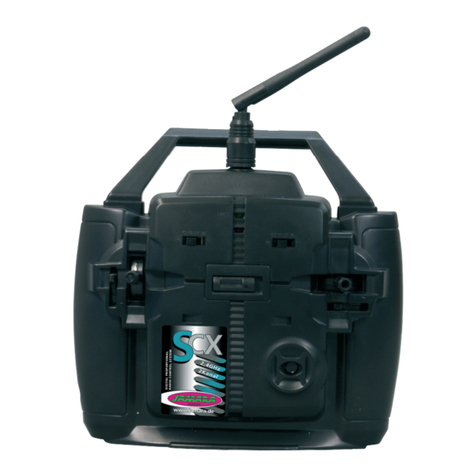
  9. Jamara CCX Lipo User manual

Jamara CCX Lipo User manual

FR - Mode d‘emploi
GB - Instruction
CCX Lipo 2,4 GHz 3 CH
Emetteur | Transmitter
No. 061201
15/1644/20
FR - Consignes générales
La société JAMARA e. K. n‘assume aucune responsabilité des dommages subis par le produit ou
occasionnés par le produit si ces dommages résultent d‘un emploi ou utilisation incorrects. Le
Client est lui-même responsable de l‘emploi et utilisation corrects, ceci comprenant en particulier
le montage, le processus de chargement, l‘application et le champ d‘application. Il faut prendre
connaissance du contenu du mode d‘emploi qui contient des informations importantes et des indi-
cations d‘avertissement.
GB - General information
JAMARA e.K. is not liable for any damage caused to the product itself or by it, if this is due to impro-
per operation or handling errors. The customer alone bears the full responsibility for the proper use
and handling, including in particular, assembling, charging and using the model, and selecting the
area in which to use it. Please refer to the operating and user instructions, which contain important
information and warnings.
FR - Déclaration de conformité
Par la présente, JAMARA e.K. déclare que le produit “CCX Lipo 2,4 GHz,
No. 061201“ est conforme à la Directive 2014/53/UE, 2011/65/UE.
Le texte intégral de la déclaration de conformité CE est disponible via l‘adresse Inter-
net suivante: www.jamara-shop.com/Conformity
GB - Certicate of Conformity
Hereby JAMARA e.K. declares that the product “CCX Lipo 2,4 GHz, No. 061201“ complies with
Directive 2014/53/EU, 2011/65/EU.
The full text of the EU Declaration of Conformity is available at the following Internet address:www.
jamara-shop.com/Conformity
Contenu du kit:
• Radiocommande
• Récepteur
• Accu LiPo 3,7 V 800 mAh 2,96 Wh,
• Câble de recharge USB
• Notice
Accessoires nécessaires
8 x piles AA Réf. 140267 (UV. 4pcs)
Equipement:
• 3 voies
• Système 2,4 GHz
• Dual Rate
• Inversion de sens de rotation des servos (Gaz/direction)
• Ajustement de la position centrale des servos
• Type de modulation AFHDS
• Type de modèle Auto, bateau
• Tension d’alimentation 3,7 V
• Seuil d’alerte de sous-tension
• Prise de charge USB
• Fail-Safe sur le récepteur
• Dimensions 156 x 223 x 94 mm
• Poids 270 g
Récepteur CCX Pro 2,4 GHz
Réf. 061185
Bande de fréquence 2,4 GHz
Type de modulation AFHDS
Tension d’alimentation 4,8 - 7,4 V DC
Résolution servo 10 Bit (1024 pas)
Dimensions 37 x 22 x 13 mm
Poids 7,6 g
Box contents:
• Transmitter
• Receiver
• Battery LiPo 3,7 V 800 mAh 2,96Wh
• USB charging cable
• Instruction
Recommended Accessories
8 x AA Batteries Ord. No. 140267 (4 pieces)
Features:
• 3 channel
• 2,4 GHz System
• Dual Rate
• Servo reverse (Gas/steering)
• Adjustment of servo centre
• Modulation AFHDS
• Model types Car, boat
• Operating range 3,7 V
• Low-Voltage warning
• Charging socket USB
• Fail Safe on receiver
• Weight 270 g
• Size 156 x 223 x 94 mm
Receiver CCX Pro 2,4 GHz
Ord.No. 06 1185
Technical data:
Frequency 2,4 GHz
Modulation AFHDS
Operating voltage 4,8 - 7,4 V DC
Servo resolution 10 Bit (1024 steps)
Dimensions 37 x 22 x 13 mm
Weight 7,6 g
Ce modèle réduit n’est pas un jouet!
Avant de mettre en marche toute l‘unité il faut lire attentivement le mode d‘emploi.
Attention! La mise en garde et les consignes de sécurités sont à lire
entièrement pour votre sécurité et éviter tout accidents et blessures.
For model building only - Not a toy!
Read the complete instructions and security instructions carefully before using the
model.
Caution! Please fully and carefully read warnings/ safety instructions.
These are for our own security and can avoid accidents/injuries.
Veillez respecter les consignes suivantes:
• Avant de mettre en marche votre récepteur, assurez-vous que le manche des gaz soit bien en
position O󰀨.
• Assurez-vous que l’émetteur et le récepteur soient compatibles et se trouvent mutuellement.
• Allumez toujours l‘émetteur en premier, puis le récepteur.
• Eteignez toujours le récepteur en premier puis votre radiocommande.
• E󰀨ectuez toujours un test de porté et de bon fonctionnement avant le décollage.
• Ne survolez jamais des personnes, ne mettez jamais en danger les gens ou les animaux.
• N‘utilisez le système ou le modèle à contrôler que sur un terrain adapté.
• N’utilisez jamais votre émetteur lorsqu’il y a une tempête, qu’il pleuve ou par orage.
• Sortez les piles de votre émetteur lorsque vous n’utilisez plus votre équipement.
Following should be strictly adhered to:
• Before Switching on the system ensure that throttle stick is in the o󰀨 position.
• Check that the transmitter and receiver are compatible and bonded to one another.
• Always switch the transmitter on  rst and then the receiver.
• Always switch the receiver o󰀨  rst and then the transmitter .
• Complete a full range and function test before every take-o󰀨 .
• Never over- y people and do not allow your model to endanger people or animals.
• Do not  y near to over-head cables, buildings or air elds.
• The system must not be operated in rain, or thunder storms.
• If you do not intend to use the transmitter for a long period, remove the batteries.
Frequency bands: 2.4 GHz Frequency range: 2405,5 – 2475,0 MHz EIRP: < 40 mW (max. power transmitted)

2
FR - Charge de l’accu
Lorsque vous mettez en place des accus NiCd ou NiMH, veillez à ce que ceux-ci soient complète-
ment chargés. Du fait que ces accus ont une consommation propre, rechargez les avant chaque
utilisation. Veillez respecter les consignes du fabricant de l’élément.
Utilisez absolument un chargeur adapté, laissez vous conseiller par votre revendeur habituel.
Après avoir complètement rechargé les éléments, débranchez le chargeur de la prise secteur.
Sortez les accus de votre émetteur et du modèle lorsque vous ne les utilisez plus pendant un certain
temps. Pour la charge de l’accu de l’émetteur procédez comme suit :
1. Mettez en place les accus en respectant la bonne polarité.
2. Branchez le chargeur sur une prise secteur.
3. Branchez le câble de charge dans la prise de charge de l’émetteur.
4. Débranchez le chargeur du secteur lorsque le processus de charge est achevé.
GB - Charging the battery
Ensure that the cells are fully charged before using the system. Please be aware that due to the
self-discharge characteristics of this type of cells that they should always be fully charged prior to
use. Please refer to the battery manufacturers recommendations regarding charging current etc.
Use only a high quality charging cable which is suitable for this type of cells. For further information
please contact your local dealer. Once charging is complete, always disconnect the batteries from
the charger.
Remove the batterie from the model and transmitter if you do not intend to operate it for a longer
period of time. To charge teh transmitter batteries please proceed as follows:
1. Fit the batterie observing the correct polarity.
2. Connect the charging cable with a suitable USB port.
3. Connect the charging cable to the transmitter.
4. Unplug the charger as soon as the batteries are full.
FR
Par l’a󰀨ectation correcte des touches, interrupteurs et indicateur LED, votre émetteur CCX-LiPo 2,4
Car peut être programmé et utilisé rapidement. Es deux canaux peuvent êtres trimmés et le sens
de rotation peut être inversé. De plus vous avez la fonction Dual Rate de disponible. Une LED vous
indique l’état de charge d l’alimentation.
GB
Thanks to the logical and well thought out lay-out of the Programming Panel and the positioning
of the switches and LEDs the CCX Lipo 2,4GHz 3CH transmitter can be quickly and simply pro-
grammed. Both channels can be trimmed and the direction changed. Furthermore the transmitter is
equipped with a Dual Rate system and a red LED indicates the state of the battery charge.
FR - Eléments de commandes
Vue de côté
1. Boite de programmation
2. Antenne 2,4 GHz
3. Volant directionnel
4. Levier des gaz
5. Compartiment d’accus/piles
6. Canal 3
Champs de programmation
7. Trim de la fonction directionnel
8. Inverseur directionnel
9. LED power
10. Interrupteur On/O󰀨
11. Inverseur de la fonction gaz
12. Touche de synchronisation
13. Trim de la fonction gaz
14. Power Check
15. Dual Rate
FR - Dos de l’émetteur
G. Prise de charge
GB - Rear Side
G. Charge Socket
GB - Controls
Side View
1. Programming Box
2. 2,4 GHz Antenna
3. Steering Wheel
4. Throttle Lever
5. Battery Hatch
6. 3-Channel
Programming Panel
7. Steering Trim
8. Steering Reverse
9. Power LED
10. ON/OFF Switch
11. Throttle Reverse
12. Binding Button
13. Throttle Trim
14. Power Check
15. Dual Rate
1
7
8
9
10
11
12
13
14
15
2
3
4
5
6
G
33
FR - Mise en place de l’ensemble de réception
Attention!
Lors de la connexion, veillez à respecter la bonne polarité des câb les (pole + et -), dans le cas
contraire le récepteur sera court-circuité.
GB - Connecting to the receiver
Warning!
To avoid any short-circuit in your receiver, please make sure to connect
the cables with correct polarity in mind.
FR - Antenne
Fixez l’antenne de réception verticalement, comme indiqué sur l’illustration. Il est interdit de xer
l’antenne sur les pièces mécaniques, la portée serait raccourcie.
GB - Antenna
Mount the 2.4 GHz antenna vertically as shown in the diagram. Do not allow any metal object to
come into contact with the antenna or to shield it as this will reduce the range.
Modèle avec propulsion électrique
Wiring diagram for electric models
Interrupteur
Switch
Interrupteur
Switch Accu de propulsion
Battery Pack
Servo des gaz
Throttle Servo
Servo directionnel
Steering
Régulateur
ESC
Servo directionnel
Steering
Voies 2
2CH
Récepteur
Receiver
Récepteur
Receiver
Accu de propulsion
Battery Pack
Moteur
Modèle avec propulsion par moteur thermique
Wiring diagram for I/C engine models
Récepteur
Receiver
2,4 GHz Antenne
2,4 GHz Antenna
Fail Safe LED
CH2
Accu / Battery
CH1
CH3/Bind
4
FR - Synchronisation du récepteur et de l’émetteur
Pour un émetteur moderne il est absolument nécessaire de synchroniser l’émetteur avec le ré-
cepteur du modèle. Après ce procédé, le récepteur n’accepte plus que les signaux émis par cet
émetteur. Si pour une raison quelconque vous souhaitez refaire une synchronisation, procédez
comme suit:
A. Mettez en place des accus chargés ou de nouvelles piles dans l’émetteur. Laissez l’émetteur
éteint en attendant.
B. Branchez le câble de synchronisation dans la sortie du canal 3.
C. Allumez le système du récepteur en connectant la batterie du récepteur au récepteur. En
fonction de la version du logiciel votre récepteur va donner des signaux di󰀨érents pour le
mode de synchronisation (au lieu de clignoter la lumière LED va par exemple briller ou
s’éteindre complètement). Le mode de synchronisation est cependant le même quelque soit la
version. La LED sur le récepteur se met à clignoter et indique donc qu’il est synchronisé
D. Restez appuyé sur la touche de synchronisation de l’émetteur et mettez le en marche.
E. L‘émetteur commence à clignoter pour indiquer qu‘il est synchronisé.
F. Relâchez la touche de synchronisation de l’émetteur et en levez la prise du récepteur.
G. Maintenant éteignez l‘émetteur. A la prochaine mise en marche de l’installation tout est
synchronisé.
H. Installez tout correctement et véri ez soigneusement le bon fonctionnement de l’ensemble.
I. Si le processus ne s’est pas e󰀨ectué avec succès, réitérez le
processus de synchronisation.
L’illustration vous montre graphiquement le déroulement de la synchronisation et désigne les dif-
férents éléments devant êtres actionnés.
GB - Binding the receiber to the transmitte
As with all modern 2.4GHz R/C systems the receiver must be bound to the transmitter to ensure that
the receiver will only react to signals from that transmitter. If you wish to re-bind the receiver with the
transmitter please proceed as follows:
A. Ensure that the transmitter is tted with fully charged batterie and leave the transmitter o󰀨.
B. Plug the binding plug (included) into the channel 3 socket on the receiver.
C. Switch the receiver system on by connecting the battery or turn in a BEC operating on a controller
to control. The receiver LED will begin to ash indicating that the receiver is in bonding mode.
D. Press and hold down the binding button on the transmitter whilst switching it on.
E. The transmitter will begin to  ash indicating that the receiver is in bonding mode.
F. Release the binding button on the transmitter and disconnect the receiver from the battery or turn
o󰀨 the controller. Release the binding plug from the receiver.
G. Switch of the transmitter. and remove the binding wire. The system be bound at the next start ..
H. Install all properly and check anything very precisely.
I. If the receiver fails to bond or does not function after bonding repeat the above procedure until a
successful bonding is achieved.
The following diagrams illustrate the bonding process and show the locations of the relevant com-
ponents.
FR - Fail Safe
Programmation de la fonction Fail Safe
1. Description de la fonction
L’unité Fail Safe intégrée est surtout d’utilité pour les bateaux et les voitures. Elle sert à éviter la
perte du modèle lorsque la fonction gaz reste accrochée lorsque le signal de commande n’est plus
réceptionné. Lorsque le récepteur perd la communication avec l’émetteur, celui-ci place automati-
quement le servo des gaz ou le régulateur dans une position préprogrammée.
2. Réglages
a. Mettez en marche l’émetteur
b. Mettez en marche le récepteur. La LED clignote continuellement et vous indique que le
récepteur est utilisable.
c. Placez le manche des gaz en position de freinage ou ralenti du servo ou du régulateur. Gardez
la commande dans cette position.
d. Appuyez sur la touche Setup du récepteur. La LED clignote durant 3 secondes (voir illustration
de gauche).
e. La position est mémorisée et vous pouvez relâcher la commande des gaz.
3. Test et réglages
a. Mettez en marche l’émetteur
b. Mettez en marche le récepteur.
c. Eteignez l’émetteur.
d. Le récepteur perd le signal et place donc le servo des gaz ou le régulateur dans la position
préprogrammée.
e. Si cela ce déroule comme indiqué vous avez programmé avec succès la fonction Fail Safe,
sinon il faut refaire un réglage
GB - Fail Safe
Programming of the integrated FailSafe unit.
1. Function Description
The function of protection of losing control is mainly for r/c boats and cars and keeps them away from
damage through throttle channel. When the receiver is out of control signal, the receiver of throttle
will automatically return to the initial position which set up before starting to avoid the error action.
2. Setting
a. Turn on the transmitter
b. Turn on the receiver. The signal LED will light continuously and indicates that the receiver is
ready.
c. Move the throttle lever on the transmitter in the braking or outlet position. Hold the throttle lever
in this position.
d. Press the Setup button on the receiver. The signal LED ashes for 3 seconds (see left).
e. The setting is saved and you can bring back the throttle into neutral position.
3. Testing the settings
a. Turn on the transmitter.
b. Turn on the receiver.
c. Turn o󰀨 the transmitter.
d. The receiver will now lose the signal and drives the servo or the speed control on the gas channel
to the previously programmed position.
e. If these steps work, you have set the FailSafe.
Touche de
synchronisation
Binding button
Connecteur de synchronisation
Binding Plug
LED
Fail Save
5
FR - Séquence de mise en marche
1. Branchez tous les composants de
votre système.
2. Mettez en marche l’émetteur.
3. Branchez l’accu de réception sur
le récepteur.
4. Surveillez la LED sur le récepteur,
celle-ci doit s’allumée continuelle-
ment.
5. Le système est mis en marche et
peut être utilisé.
Séquence d’arrêt
1. Déconnectez l’accu de réception
2. Arrêtez l’émetteur
FR - Pilotage du modèle
Avec cette fonction vous dirigez votre modèle en actionnant la direction de celuici.
Lorsque vous tournez le volant de la radiocommande, les roues de l’axe avant doivent également
s’incliner dans la même direction. Lorsque vous tournez le valant sur votre droite, les roues doivent
s’incliner à droite comme indiqué sur l’illustration cicontre.
Sur l’illustration en-dessous vous réalisez un virage à gauche. Avec l’interrupteur (6) dans la zone de
programmation vous pouvez, si nécessaire, changer le sens de rotation d la direction. Pour obtenir
un pilotage plus  n, utilisez la fonction Dual Rate au travers de la touche Dual Rate. L’amplitude de
commande dans la zone du neutre de la commande de gaz n’induit qu’un petit mouvement de la di-
rection. Néanmoins tout le débattement reste disponible pour e󰀨ectuer des demitours par exemple.
GB - Operating the model
This function is used to steer the model and turning the steering wheel will make the models wheels
to turn in the relevant direction. Turning the wheel to the right will make the models wheels turn to
right when viewed from above as illustrated. Moving the wheel to the left will cause the wheels to
turn to the left.
By operating the relevant switch (6) on the programming panel the direction in which the steering
moves can be reversed if required. In addition, the transmitter is equipped with a Dual Rate function.
When this function is activated the wheels of the model will move less relative to the movement of
the transmitters steering wheel around the middle position. This will allow the model to be steered
with more precision however if this function is used the total throw will still be available
for tight cornering when the steering wheel is moved to the end of it’s range.
GB - Switch on
1. Plug in all of the components.
2. Switch the transmitter on.
3. Connect the receiver battery to the
receiver.
4. Check that the LEDs on both the
transmitter and the receiver illuminate
solidly.
5. The system is now correctly switch
on and operating and can now safely
be used.
GB - Switching o󰀨
1. Disconnect the receiver battery
2. Switch o󰀨 the transmitter
Mise en marche
Switching On
1. Mettre en marche
l’émetteur
1. Switch the
transmitter on
2. Mettre en marche le
récepteur
2. Switch the
receiver on
1. Arrêter le
récepteur
1. Switch o󰀨
the receiver
2. Arrêter l‘emeteur
2. Switch o󰀨 the
transmitter
Arrêt de l’ensemble
Switching O󰀨
Direction
Steering
6
Gaz
Trottle Lever
FR - Gaz
Avec cette fonction vous déterminer si vous roulez en avant ou en arrière ainsi que la vitesse.
Lorsque vous tirez la commande de gaz en arrière, le modèle va en avant comme indiqué sur
l’illustration ci-contre.
Lorsque vous poussez la commande de gaz en avant comme indiqué sur l’illustration ci-contre, le
modèle freine dans un premier temps puis recule. Bien sur ici il est question d’une voiture à propul-
sion électrique avec régulateur compatible marche arrière
GB - Trottle Lever
This function is used to control the models speed both forwards and in reverse as shown in the
illustration to the left. If the lever is pulled back towards the transmitter grip the model will accelerate
forwards.
If the lever is pushed away from the transmitter grip the model will rst brake and then accelerate
in reverse. This is providing that the model is tted with a Speed Controller which supports these
functions.
FR - Commutateur pour troisième canal:
Si un asservissement sur le troisième canal de déviation maximale gauche / droite.
GB - Auxiliary Channel 3 Switch:
Controls auxiliary channel 3 high and low servo travel.
CH 3
7
FR - Revendeur de service GB - Service centre
Reitter Modellbau Versand
Patricia Reitter
Degerfeldstrasse 11
72461 Albstadt
Tel 07432 9802700
Fax 07432 2009594
Mail [email protected]
Web www.modellbauversand.de
Modellbau-Zentral
Peter Hofer
Bresteneggstrasse 2
CH -6460 Altdorf,
Tel. +41 794296225
Fax +41 418700213
[email protected]
www.modellbau-zentral.ch
PenTec s.r.o.
distributor Jamara for Czech Republic and Slovakia
Veleslavínská 30/19
CZ -162 00 Praha 6
Tel +420 235 364 664
Mobil. +420 739 075 380
Mail servis@topdrony.cz
Web www.topdrony.cz
Bay-Tec
Martin Schaaf
Am Bahndamm 6
86650 Wemding
Tel 07151 5002192
Fax 07151 5002193
Mail [email protected]
Web www.bay-tec.de
DE DE
JAMARA e.K.
Manuel Natterer
Am Lauerbühl 5
DE-88317 Aichstetten
Tel +49 (0) 75 65/94 12-0
Fax +49 (0) 75 65/94 12-23
Mail [email protected]
Web www.jamara.com EU
CH CZ
JAMARA e.K.
Inh. Manuel Natterer
Am Lauerbühl 5 - DE-88317 Aichstetten
Tel. +49 (0) 75 65/94 12-0 - Fax +49 (0) 75 65/94 12-23
[email protected] ●www.jamara.com
Service - Tel. +49 (0) 75 65/94 12-777
kundenservice@ jamara.com
Irrtum und technische Änderungen vorbehalten. Copyright JAMARA e.K. 2021
Kopie und Nachdruck, auch auszugsweise, nur mit Genehmigung von JAMARA e.K.
All rights reserved. Copyright JAMARA e.K. 2021
Copying or reproduction in whole or part, only with the expressed permission of JAMARA e.K.
Fordern Sie noch Heute den aktuellen Hauptkatalog mit
unserem gesamten Warensortiment an.
Name _______________________________
Vorname _______________________________
Straße _______________________________
Wohnort _______________________________
Telefon _______________________________
E-mail _______________________________
Bitte senden Sie den Katalog für mich an folgenden
Fachhändler:
Ihr Fachhändler
_______________________________________________
_______________________________________________
_______________________________________________
_______________________________________________
Der Katalog wird mit der nächsten Bestellung des Händ-
lers auf Ihren Namen mitgeliefert.
Order the current catalogue with our complete
assortment of modelling goods today.
Name _______________________________
First name _______________________________
Street _______________________________
City _______________________________
Phone _______________________________
E-mail _______________________________
Please send the catalogue to the following specialist
dealer:
Your dealer
_______________________________________________
_______________________________________________
_______________________________________________
_______________________________________________
We will include a catalogue for your attention with the
next order placed by your dealer.
Gutschein Coupon

Other manuals for CCX Lipo

3

Other Jamara Transmitter manuals

Jamara FCX6 Pro Tel User manual

Jamara

Jamara FCX6 Pro Tel User manual

Jamara Compa X3 Evo User manual

Jamara

Jamara Compa X3 Evo User manual

Jamara FCX6 Pro Tel User manual

Jamara

Jamara FCX6 Pro Tel User manual

Jamara CCX Pro User manual

Jamara

Jamara CCX Pro User manual

Jamara FCX6 Pro Tel User manual

Jamara

Jamara FCX6 Pro Tel User manual

Jamara CCX Lipo User manual

Jamara

Jamara CCX Lipo User manual

Jamara CCX Pro 2,4 GHz User manual

Jamara

Jamara CCX Pro 2,4 GHz User manual

Jamara CX 2,4 GHz User manual

Jamara

Jamara CX 2,4 GHz User manual

Jamara CCX Lipo 2,4 GHz 3 CH User manual

Jamara

Jamara CCX Lipo 2,4 GHz 3 CH User manual

Jamara Compa User manual

Jamara

Jamara Compa User manual

Jamara CCX Pro 2,4 GHz User manual

Jamara

Jamara CCX Pro 2,4 GHz User manual

Jamara CCX Pro 2,4 GHz User manual

Jamara

Jamara CCX Pro 2,4 GHz User manual

Jamara SCX User manual

Jamara

Jamara SCX User manual

Jamara CCX Lipo User manual

Jamara

Jamara CCX Lipo User manual

Jamara CCX Pro User manual

Jamara

Jamara CCX Pro User manual

Jamara FCX6 Pro Tel User manual

Jamara

Jamara FCX6 Pro Tel User manual

Jamara SCX 2,4 GHz User manual

Jamara

Jamara SCX 2,4 GHz User manual

Jamara SCX 2,4 GHz User manual

Jamara

Jamara SCX 2,4 GHz User manual

Jamara SCX User manual

Jamara

Jamara SCX User manual

Jamara FCX6 Pro Tel User manual

Jamara

Jamara FCX6 Pro Tel User manual

Jamara SCX User manual

Jamara

Jamara SCX User manual

Jamara Compa XR3 User manual

Jamara

Jamara Compa XR3 User manual

Jamara CCX Pro 2,4 GHz User manual

Jamara

Jamara CCX Pro 2,4 GHz User manual

Jamara CCX Pro User manual

Jamara

Jamara CCX Pro User manual

Popular Transmitter manuals by other brands

Richelieu TXRF24B2 operating instructions

Richelieu

Richelieu TXRF24B2 operating instructions

Status SEM315 user guide

Status

Status SEM315 user guide

Radio Shack Audio/Video Signal Sender owner's manual

Radio Shack

Radio Shack Audio/Video Signal Sender owner's manual

MYE MWCS-AT9-LFA manual

MYE

MYE MWCS-AT9-LFA manual

Honeywell 5814 - Ademco Ultra-small Wireless... installation instructions

Honeywell

Honeywell 5814 - Ademco Ultra-small Wireless... installation instructions

Backgrounds Unlimited TXBD12A user manual

Backgrounds Unlimited

Backgrounds Unlimited TXBD12A user manual

Salcom 11-85 Operator's manual

Salcom

Salcom 11-85 Operator's manual

Pro-Tronik PTR-6A user manual

Pro-Tronik

Pro-Tronik PTR-6A user manual

Konig BTRC100BK manual

Konig

Konig BTRC100BK manual

NORMARC 7033 manual

NORMARC

NORMARC 7033 manual

GEIGER GF20 Series Original assembly and operating instructions

GEIGER

GEIGER GF20 Series Original assembly and operating instructions

RIB NOVA Wi-Fi manual

RIB

RIB NOVA Wi-Fi manual

MEE AUDIO AF-CH quick start guide

MEE AUDIO

MEE AUDIO AF-CH quick start guide

FIP FLS M9.07 instruction manual

FIP

FIP FLS M9.07 instruction manual

Navitel BHF06 PRO user manual

Navitel

Navitel BHF06 PRO user manual

LG Wowcast WTP3 Simple manual

LG

LG Wowcast WTP3 Simple manual

Delta Electronics OIB-3 Instruction book

Delta Electronics

Delta Electronics OIB-3 Instruction book

Prevail-Catv WT-1550-EML manual

Prevail-Catv

Prevail-Catv WT-1550-EML manual

manuals.online logo
manuals.online logoBrands
  • About & Mission
  • Contact us
  • Privacy Policy
  • Terms and Conditions

Copyright 2025 Manuals.Online. All Rights Reserved.