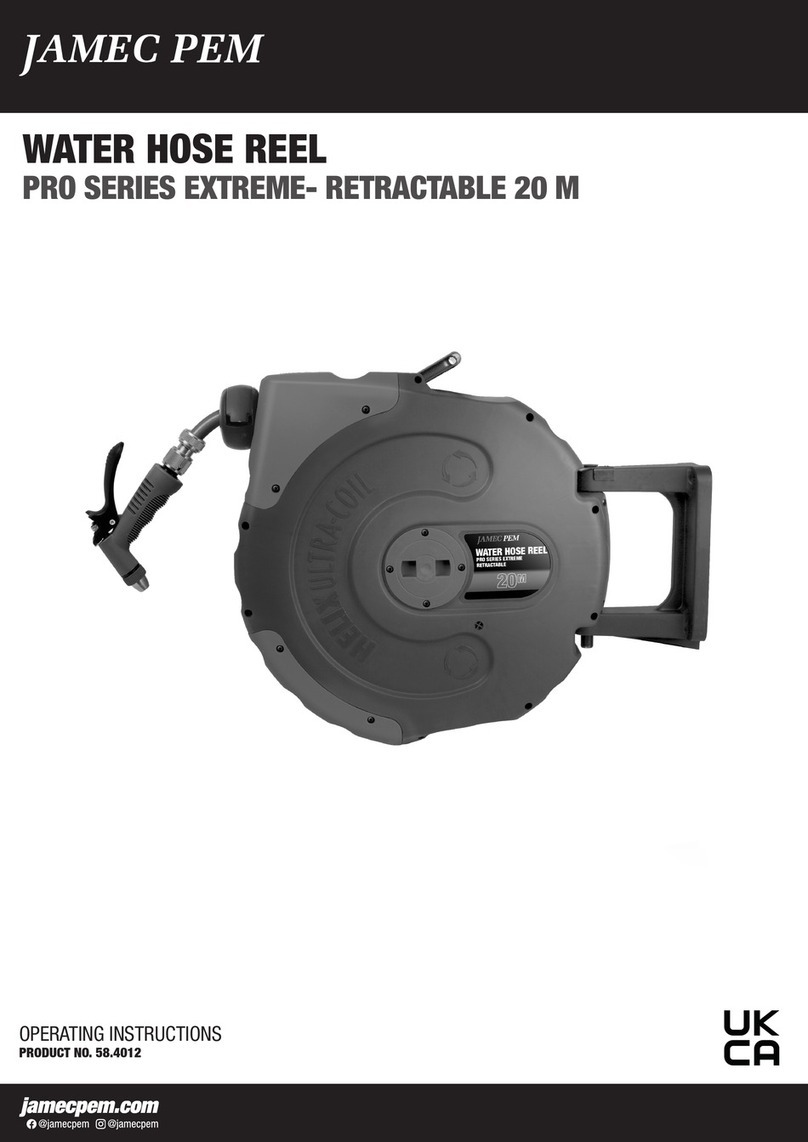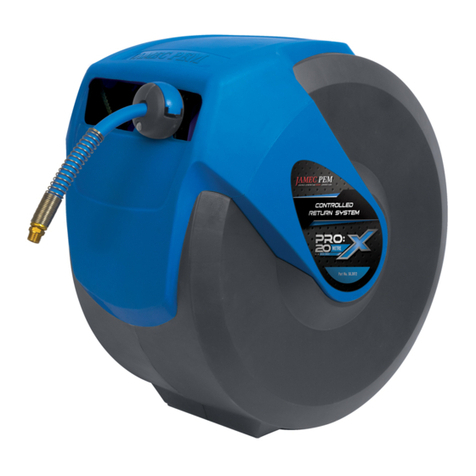
WATER HOSE REEL
PRO SERIES - CONTROLLED RETURN
20 M
With the unique Helix Ultra-Coil hose layering system, combined with a precision
machined solid brass central spindle, the Jamec Pem Pro Series Hose Reels are
ideally suited for the trade or industrial workshop
FEATURES
Improved safety feature: controlled hose return
Auto lock / rewind
Solid brass internal spindle
Adjustable hose stop
Wall mount with 180° pivot
Weather resistant UV stabilised polypropylene case
Leader hose 2 m with brass ttings
Includes water trigger gun
SPECIFICATIONS
Hose length 20 m
Hose I.D 11.5 mm (1/2")
Hose O.D 16 mm (5/8")
Leader hose length 2 m Brass tap female tting
Hose material Reinforced PVC braided
Reel / case type Controlled return / polypropylene
Auto lock / rewind Yes
Max. working pressure 150 psi
Fitting size 12 mm Tap ttings
Bracket 180° Pivoting
Product dimensions 440 L x 210 W x 400 H mm
Weight 8.2 kg
Application Water
MAINTENANCE
Always keep the hose clean.
If the hose becomes dirty, clean it with a damp cloth while retracting.
DO NOT twist the hose while in use.
Mount the hose reel in a sheltered area to assist and protect the performance of
the hose and hose reel.
DO NOT allow the hose to contact any corrosive chemicals or uids.
Always retract the hose when not in use.
The JamecPem Water Hose Reel Pro Series Controlled Return contains a pre-
tensioned spring inside the inner drum assembly.
Do not attempt to open the inner drum assembly.
PRODUCT IDENTIFICATION
1. Mounting bracket
2. Optional xed in-line
locking plate
3. Pivot pin
4. Fully enclosed case
5. Carry handle
6. Solid brass internal
spindle
7. 2 Metre leader hose
8. Hose with adjustable
stopper
9. Water gun
1
4
8
7
2
3
6
9
5
INSTALLATION
The JamecPem Water Hose Reel Pro Series Controlled
Return can be mounted in a horizontal or vertical position.
1. Chose a location that is near to the water source.
2. For large areas, place the hose reel at the centre of the
work area.
3. When mounting the hose reel vertically, ensure there is
adequate clearance under the reel to prevent injury or
damage.
4. Mounting bracket must be installed on a at surface.
5. Note: It is recommended to install the mounting bracket
0.8 metre (minimum) above the oor level.
6. Drill 4 x M8 holes to match the holes located in the
Mounting Bracket.(Fig. 1)
7. Connect the hose reel to the Mounting Bracket with the
Pivot Pin.(Fig. 2)
Note: For xed in-line position, t the locking plate onto the
Mounting Bracket prior to inserting the pivot pin. (Fig. 3)
8. Connect the inlet leader hose to the water source using
the tap ttings supplied.
0.8 metre min.
Fig. 1 Mounting Bracket
Fig. 2 Pivot Pin
Fig. 3 Locking Plate
OPERATION
1. Slowly pull out the hose to the required length. A‘clicking’ noise will be heard
every revolution of the inner drum. To lock the reel, allow the hose to retract slowly
after hearing the second or third ‘click’.
2. To release the hose, pull out the hose until the ‘clicking’ noise stops, and then
allow the hose to slowly retract while guiding the hose back into the hose reel. The
self layering mechanism will coil the hose back onto the inner drum.
3. To avoid injury and damage, always hold the hose while it is retracting.
IMPORTANT:
If the hose becomes tangled and will not retract - slowly pull out the hose
past the tangled section and then allow the hose to slowly retract while
guiding the hose back into the hose reel.
Always ensure the hose is clean and not twisted.

