Page 9
ENGLISH
Jandy®Laminar Jet | Installation and Operation Manual ENGLISH
3.3 Pressure Test Water Lines
The maximum operating pressures for pumps,
filters, and other equipment are specified in their
individual installation/operating instructions.
Never subject the system to test or operating
presures exceeding these specifications.
Pressures above maximum component
operating ratings can cause product failure, or
also cause the filter lid to be blown off, or other
equipment failure which can result in death,
serious personal injury, or property damage.
WARNING
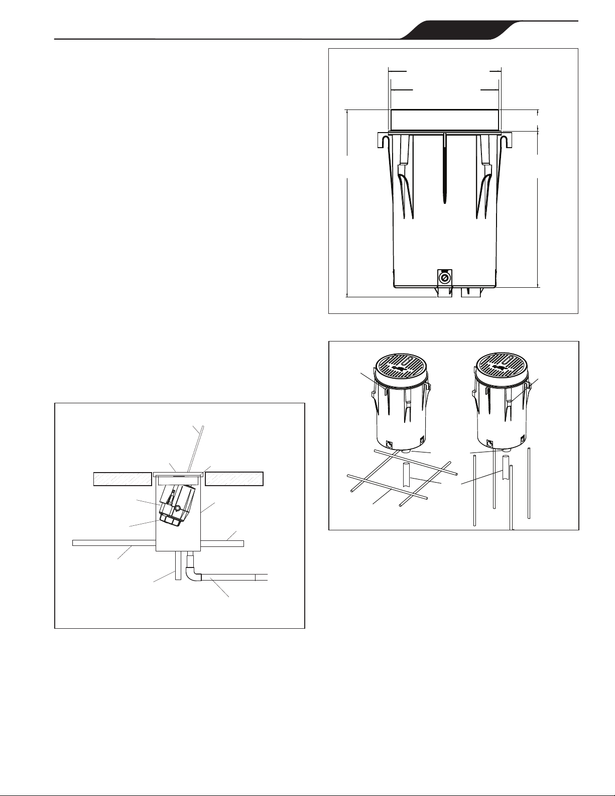
The unit is shipped ready for the pressure test with a cap
on the exible hose that is attached to the canister.
NOTE: This cap can be used to winterize the system or
service the unit, if needed.
When performing hydrostatic pressure tests or when
testing for external leaks of the completed ltration and
plumbing system, ensure that the maximum pressure
the ltration system is subjected to does not exceed the
maximum working pressure of any of the components
within the system.
3.4 Flush Water Lines
It is important that prior to reinstalling the laminar jet
and deck canister lid, the installer must turn on the
water source and ush the lines of any debris.
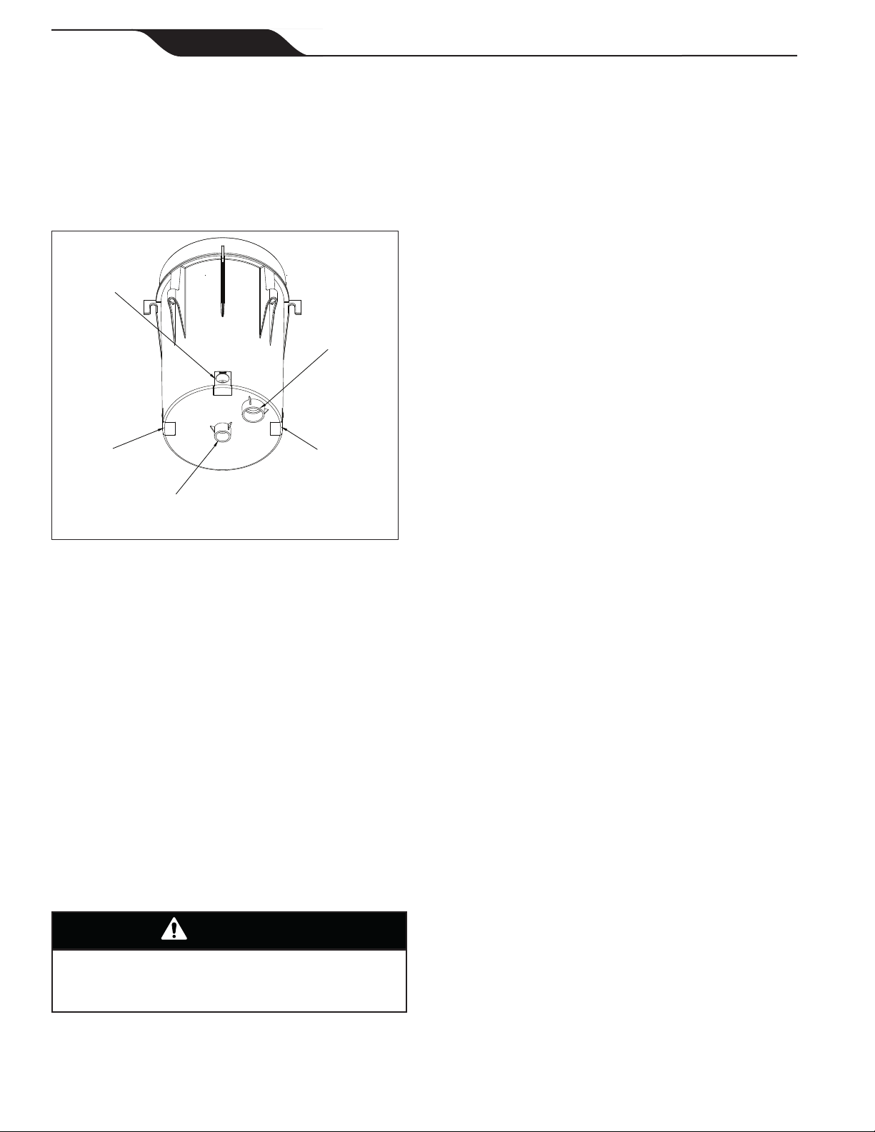
NOTE: The nger screen is installed in the tting
under the cap. Remove the nger screen when
ushing the line and reinstall the screen when
reinstalling the cap or the jet assembly.
Section 4. Laminar Jet with LED
Light Installation (Use with JLLED4C Series)
Risk of Electrical Shock or Electrocution
which
may result in serious injury or death. The Jandy Laminar
Jet are only available for 12-volt AC power. For supply
connection, use only an isolating low voltage power supply
with ungrounded output, listed by an NRTL for swimming
pool use. A Ground Fault Circuit Interrupter (GFCI) for
120 Volt transformers should be used if required by
the transformer manufacturer or if required by the local
applicable code and/or Authority Having Jurisdiction
(AHJ). When a GFCI is used, the conductors on the
load side of the GFCI circuit shall not occupy conduit,
boxes, or enclosures containing other conductors unless
the additional conductors are also protected by a GFCI.
Refer to local codes for complete details
. This laminar jet
with LED light must be installed by a licensed or certified
electrician or a qualified pool serviceman in accordance
with the National Electrical Code
®
and all applicable local
codes and ordinances. Improper installation will create an
electrical hazard, which could result in death or serious
injury to pool or spa users, installers or others due to
electrical shock, and may also cause damage to property.
WARNING
Always disconnect the power to the laminar jet with
LED light at the circuit breaker before installing or
servicing the light. Failure to do so could result in
death or serious injury to serviceman, pool or spa
users or others due to electrical shock.
WARNING
4.1 Preparing the Laminar Jet with LED
Light for Installation
NOTE: The electrician must complete preparatory steps
before the laminar jet with LED light is installed.
Ensure that the pool meets the requirements of the
current National Electrical Code and all local codes
and ordinances. A licensed or certied electrician must
install the electrical system to meet or exceed those
requirements before the laminar jet with LED light is
installed. Some of the requirements of the National
Electrical Code, which the pool electrical systems must
meet, are as follows:
1. The low voltage transformer must be located at
least 8 inches (20 cm) above water level, at least
4 inches (10 cm) above ground level, and at least
4 feet (1.2 m) from the edge of the pool.
2. All metal items within 5 feet (1.5 m) of the pool
must be properly electrically bonded to a reliable
point of grounding.
4.2 Installing the Laminar Jet with
LED Light
NOTE: Perform these steps only after the electrical
system requirements are met.
1. Feed cord through conduit to low voltage
transformer, leaving at least 4 feet of cord at the
light fixture to coil into the deck canister. The 4 feet
(1.2 m) of cord allows the light to be easily serviced.
2. Cut the cord at the low voltage transformer,
leaving at least 6 inches (15 cm) of cord to make
connections.
3. Strip 6 inches (15 cm) of the outer cord jacket to
expose the three (3) insulated wires. Be careful
not to damage the insulation on the three (3)
inner wires.
4. Install strain relief over cord jacket and connect all
three (3) wires to the corresponding circuit wires
in the low voltage transformer. Install the low
voltage transformer cover.
5. Turn on main switch or circuit breaker, and the
switch, which operates the laminar jet with LED
light, to check for proper operation. Refer to
operating instructions.