Page 6 C artridge Pool Filters - C L and C V S eries Filters
Section 3. Installation Instructions
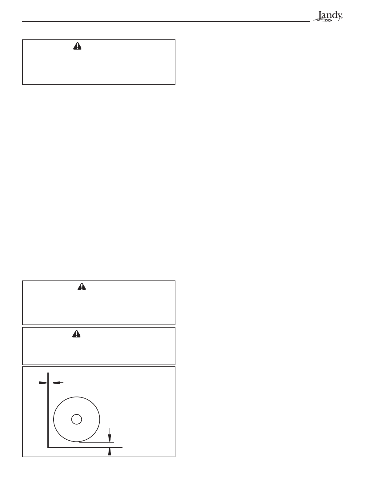
3.1 Filter Location
when it rains. Damp, non-ventilated areas should
be avoided.
system. Install system on a concrete slab or solid
concrete blocks to avoid risk of settlement. Do not
away. Filter systems can weigh up to 800 lbs.
permit a visual inspection of the clamp ring (see
Fig. 2).
servicing.
Align the air release valve to safely direct purged
air or water.
F I LT E R
Figure 2 . Filter Loc ation
6"MINIMUM
CLE A R A N CE
6"MINIMUMCLEARANCE
C A U T I O N
M a i n t a i n yo u r p r e ssu r e g a u g e i n g o o d w o r ki n g
o r d e r . T h e p r e ssu r e g a u g e i s t h e p r i m a r y i n d i ca t o r
o f h o w t h e f i lt e r i s o p e r a t i n g .
W A RN I N G
W a t e r d i sch a r g e d f r o m a n i m p r o p e r l y p o si t i o n e d
f i l t e r o r va l ve ca n cr e a t e a n e l e ct r i ca l h a za r d
w h i ch ca n ca u se d e a t h , se r i o u s i n j u r y o r p r o p e r t y
dam age.
level of the pool, it can be raised 2.5 ft. without
recommended on the suction line to the pump.
of the pool, isolation valves should be installed on
both the suction and return lines to prevent back
that may be required.
3.2 Anchor Bracket Installation
In some areas, for example Florida, building codes
require that all appliances be securely fastened to the
equipment pad in order to withstand high wind pressures
created by hurricanes. Jandy provides an anchor bracket
kit for this purpose. Please see the Parts List in Section
9 of this manual for the correct part number. Follow the
Anchor Bracket Installation Kit Instructions to attach
N O T E A n ch o r scr e w s a n d w a sh e r s f o r se cu r i n g t h e
a n ch o r b r a cke t t o t h e e q u i p m e n t p a d a r e n o t
includedwiththelterortheanchorbracket
ki t . Ja n d y r e co m m e n d s t h a t a ¼ " x 2¼ " l o n g
st a i n le ss st e e l T a p co n ®co n cr e t e scr e w a n d
stainlesssteelatwasherareusedtomount
e a ch a n ch o r b r a cke t t o t h e e q u i p m e n t p a d . T h e
T a p co n co n cr e t e scr e w m e e t s F l o r i d a b u i l d i n g
co d e r e q u i r e m e n t s.
concrete drill bit should be obtained when the concrete
screws are purchased.)
Install the Tapcon®screws and washers through each
equipment pad. See Figure 3. Do not over-torque the
screws.
3.3 Filter Preparation
1. Check carton for damage due to rough handling
damaged, notify carrier immediately.
2. Carefully remove the accessory package.
3. A visual inspection of all parts should be made
now. See parts list in Section 9.
4. With the carton in an upright position, remove the
bag):
a. Place the smaller, thicker o-ring onto the
threads of the tank adapter (see Figure 4).
Slide the tank adapter through the coupling
W A RN I N G
U se e q u i p m e n t o n l y i n a p o o l o r sp a i n st a l l a t i o n .
D o n o t co n n e ct sy st e m t o a n u n r e g u l a t e d ci t y w a t e r
syst e m o r o t h e r e x t e r n a l so u r ce o f p r e ssu r i ze d
waterproducingpressuresgreaterthan35psi.