jbc TE 5400 User manual

TE 5400
PRECISION HOT-AIR STATION
Index Page
English 1
Español 9
Français 17
Deutsch 25
Italiano 33
Reference Guide

1
ENGLISH
We appreciate the trust you have placed in JBC in purchasing this station. It is
manufactured to the most strictest quality standards in order to give you the best
possible service. Before turning on your station, we recommend you read these
instructions carefully.
Extractor stand
Ref. 0792800
TE 5400
Precision hot-air
station
Tripod
Extractor
Protector
TE 8600 heater stand
Ref. 0798600
TE 5400 Heater
Ref. 0781117
Control
Unit
Selector for
tripods and
extractors
Nozzle
0990330 Ø2
0990350 Ø2,5
0990370 Ø3
0990410 Ø4

2
ENGLISH
SPECIFICATIONS
The station TE 5400 is used for desoldering and
soldering of small and medium sized SMD's by
hot-air.
-TE 5400 230V Ref. 5400200
-TE 5400 120V Ref. 5400100
TE 5400 is also sold supplied without extractors
or protectors:
-TE 5400 230V WE Ref. 5410200
-TE 5400 120V WE Ref. 5410100
The station’s components
- Control unit with heater 200W
-TE 8600 heater stand Ref. 0798600
- Extractor stand Ref. 0792800
- Set of 5 protectors.
- Set of 3 extractors.
- 2 tripods for the protectors.
- Set of 4 suction cups Ref. 0930110
- Suction tube with connectors Ref. 0932330
- 4 nozzles:
ø 2 Ref. 0990330
ø 2,5 Ref. 0990350
ø 3 Ref. 0990370
ø 4 Ref. 0990410
In order to make the nozzles removal easier, the
stand has a special bushing.
- Instruction manual Ref. 0002754
The pedal ref. 0964551 can be connected to
the connector placed at the rear of the station.
This article is not delivered with the station.
Safety measures
- Incorrect use of this tool may cause fire.
- Be cautious when using the tool in places
where inflamable products are stored.
- Heat can cause fire to inflamable products
even when they are not in sight.
- Do not use when the atmosphere is
explosive.
- Place the tool back on its stand in order to
let it cool down before you store it.
This product should not be thrown in the
garbage.
Control unit technical specifications
- Temperature selection from 150 to 450°C (300
to 850°F).
- Accuracy of selected temperature: ±5%.
- Air flow regulation: 4-12 l/min.
- Station's maximum power: 225W.
- ESD protected housing.
Typical surface resistance: 105-1011Ohms/
square.
- Equipotential connector and the metallic part
of the heating element are connected to
station mains ground supply for ESD
protection.
- Complies with CE standards on electrical
safety, electromagnetic compatibility and
antistatic protection.
- RoHS compliant.
- Weight of complete unit: 11.2 kg (28 lbs).

ENGLISH
3
OPERATION
Description of controls
-BUTTONS:
HEATHEAT
HEATHEAT
HEAT. Activates or deactivates the air flow. The
hot-air flow automatically turns off after the
selected time.
SUCTIONSUCTION
SUCTIONSUCTION
SUCTION. On/off switch for the self-contained
suction pump.
KEYSKEYS
KEYSKEYS
KEYS and
. Decrease or increase the
temperature of the handpiece. This enables
temperatures from 150 to 450°C (300 to 840°F)
to be selected.
The selected temperatures are reference values
which may change depending on the distance
between the heating element and the nozzle.
The display shows the actual air temperature
when the unit is working measured at a distance
of 10mm from the nozzle.
SELECTSELECT
SELECTSELECT
SELECT. It allows the access to the SETUP
mode of the station.
-CONTROLS:
AIR FLOW
This enables the air flow to be set on a scale
from 1 (corresponding to the lowest setting of
4 l/min) to 10 (corresponding to the highest of
12 l/min).
-PEDAL:
Hot air is produced when it is held down.
Releasing it the heater is disconnected,
though the turbine continues to operate until
the air temperature falls below 100°C (212°F)
Air flow
regulation
Heater inlet
Suction selector
for tripods and
extractors
Heating element ON-OFF switch
Vacuum pump
selection
Temperature increase
Temperature decrease
SETUP mode
selection
Pedal
Ref. 0964551
-VACUUM SELECTOR:
Two vacuum inlets avalaible for tripods and
extractors, being active the one that coincides
with the arrow.

4
ENGLISH
If you press keys or once, the display will
show the working parameters of the station:
temperature, air flow and automatic working
time of the heater.
If you keep the keys or constantly pressed
or make several taps, the selected temperature
increase or decrease in steps of 10ºC (20ºF).
Turning on
Turn on using the switch on the rear of the
control unit. The program version will first
appear on the screen and then it will display
OFF.
Modify or display the temperature
Activating/deactivating the heater
Mode T off
In this mode, the station desactivates the heating
element and produce air-flow but whitout heat it.
In order to activate this function, press key
since the display shows T off:
If the temperature of the heater is lower than 50ºC
(100ºF) display will show:
SEL T AIR SELt
350ºC 100% 2:00
SEL T AIR SELt
T OFF 100% 2:00
SEL T AIR SELt
COOL 100% 2:00
SEL T AIR SELt
350ºC 100% 2:00
TE 5400 STATION
OFF
In order to activate the heater, press HEAT, the
display will briefly show ON and it will show the
station parameters after.
If you want to modify or see the selected
temperature press keys or .
Station SETUP mode
The station must be stopped to enter into
this mode, the display will show:
Then hold down the SELECT button until the
screen below shows:
In order to deactivate the heater, press HEAT
again. The station will remain on during a few
seconds till the heater gets cool. During this
period, the display will show:
Temperature unit change (ºC / ºF)
Switch off the station. Press and keep the
SUCTION key pressed and switch on the station.
After a few seconds, the display will show the
temperature unit selected.
Release the SUCTION key in order to work
normally.
In order to change the temperature unit again
follow the steps mentioned above.
TE 5400 STATION
COOLING...
When the heater stops, the display will show:
TE 5400 STATION
OFF
TEMPERATURE UNIT
CELSIUS
TE 5400 STATION
OFF
TE 5400 SETUP
If you would like to change the parameters,
as any other function, see page 41.

ENGLISH
5
The following values are show as a guide for
each application:
Soldering
small 300°C (572°F) 1 - 2
components
Soldering
medium and 350°C (662°F) 1 - 7
large comp.
Desoldering 300°C (572°F)
small or 1 - 4
components 350°C (662°F)
Desoldering 400°C (752°F) 7
medium and or or
large comp. 450°C (842°F) Maximum
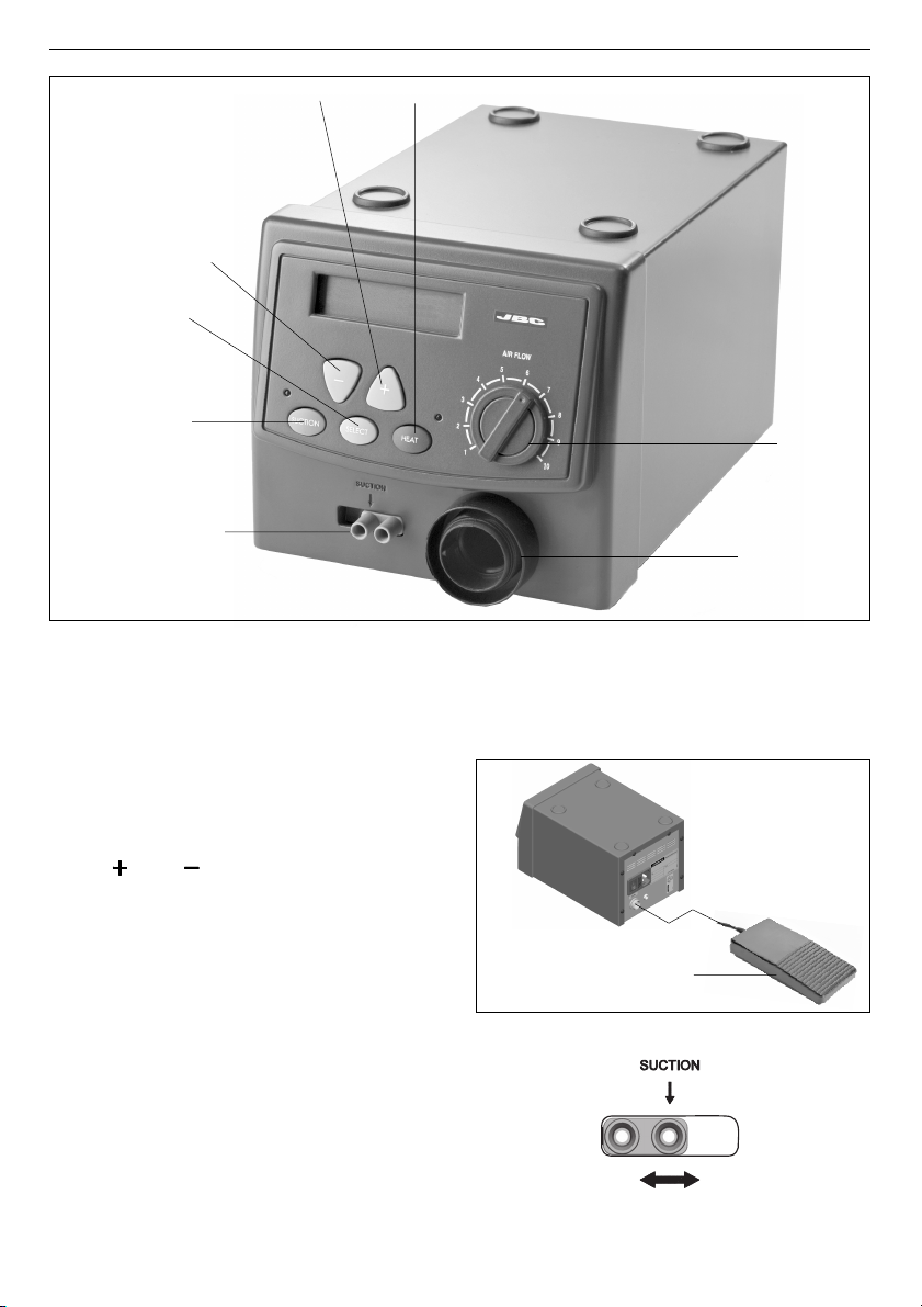
Air
Flow
Temp.
RECOMMENDATIONS FOR SOLDERING
AND DESOLDERING
In hot-air soldering and desoldering processes,
melting point is reached as a result of the heat
applied, the function of the air being to bring the
required heat to bear on the components. It is
therefore very important to select the lowest
possible air flow, and we recommend that the
heater be used without a nozzle whenever
possible, thus avoiding components being
shifted and solder being driven out.
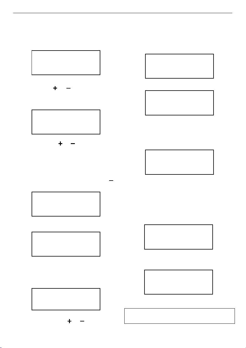
2) Temperature 300°C (572°F), air flowrate 1-2.
SEL T AIR SELt
300ºC 20% 2:00
For soldering
Process for small SMD components of two or
three pins such as heating elements,
capacitors, transistors, etc:
1) If the component has been desoldered
previously, any traces of solder left on the
circuit pads must be cleaned up by DR 5650
desoldering iron suction ref. 5650000.
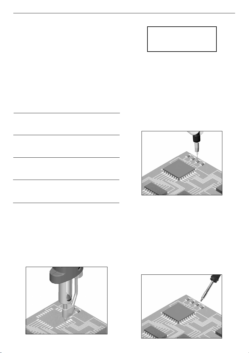
3) Apply soldering cream (*) for SMD on the
circuit pad. For application we recommend
our model DP 6070 dispenser or any other
available on the market.
The amount of cream used for each soldering
operation should be just sufficient to cover
the trace of the component pin. Any excess
cream may extend over the circuit on melting
and cause short-circuits.
4) Take the component with a JBC PK 6060 or
DP 6070 Pick & Place or otherwise with fine
pincers, place it in position on the circuit and
hold it in place.
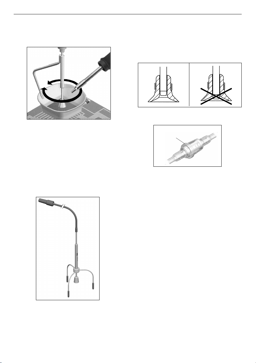
5) Move the nozzle tip to about 15-20 mm
from the component terminal and direct
the hot air flow against it. Wait for a few
seconds until the cream flux liquefies.
During this time the terminal will be
preheated to about 100°C (212°F). Move
the tip closer to 8-10 mm and hold it just
until the tin alloy melts. Immediately
remove the heater. If the solder area is
overheated, it oxidizes making soldering
difficult and there is a risk of damaging
the component or the printed circuit
copper adhesive.

For desoldering
Temperature from 400 to 450°C (752 to 842°F),
an air flowrate from 7 to maximum, depending
on the size of the component.
Depending on the size of the integrated circuit
to be desoldered, you will have to use:
A) Protector + tripod.
B) Extractor.
C) Tripod.
A)Protector + tripod:
- Select protector and tripod size in function of
the IC to be desoldered and place it over the
component.
- Use the SUCTION button to start the pump
and then place the tripod. Press the suction
cup until it sticks onto the component.
(*) Alloy 62 Sn/ 36 Pb/ 2 Ag Type RMA/CMA.
ENGLISH
6
Process for printed circuits in PLCC, QFP, SO
encapsulations:
1) Temperature of about 350°C (662°F), air
flowrate 1-7.
2) Apply soldering cream (*) for SMD on the
circuit pads, forming a bead transverse to
the direction of the tracks. In this operation,
it is vital not to apply too much cream,
since any excess may lead to solder
cross-connections being formed between
the component’s pins.
3) Take the component with the PK 6060 or DP
6070 Pick & Place, place it in position on the
circuit and hold it in place.
4) Use the heater like the previous case,
advancing slowly from one extreme to
another of the pins line.
SEL T AIR SELt
350ºC 50% 2:00
SEL T AIR SELt
400ºC 50% 2:00
- When the soldering flux turns liquid the
extractor will automatically lift the component.
B)Extractor:
- Select extractor size in function of the IC to
be desoldered. Use the SUCTION button to
start the pump.
- Use the pedal or the HEAT button to start the
self-contained hot-air pump, directing it with a
circular movement at the component terminals
and taking care to distribute the heat evenly.
- Place the extractor and press the suction cup
until it sticks onto the component.

7
ENGLISH
- When the soldering flux turns liquid the
extractor will automatically lift the component.
There are different models of protectors and
extractors as accessories.
C)Tripod:
For small components for which an extractor
cannot be used, we recommend use of tripod 20
Ref. 0932050, as shown in the figure.
Use the tripod 40 Ref. 0932250 for larger integrated
circuits.
- Use the pedal or the HEAT button to start the
self-contained hot-air pump, directing it with a
circular movement at the component terminals
and taking care to distribute the heat evenly.
Possible errors
In the case of malfunction, the control unit
interrupts the connection.
Following a list of the most common
malfunctions:
--
--
- Power failure.
Check for blown fuses.
- The temperature will not rise.
Possible causes:
· Heating element open.
· In case of a long low-power period.
- No reading from the thermocouple.
Possible cause: open thermocouple.
- Insufficient air flow which causes an excesive
rise of the heating temperature.
Before recuperating this type of error you must
wait until the temperature goes down.
Possible causes: leaking or blocked air
conducts or faulty self-contained air pump.
- Faulty reading of the rotationsmeter of the self-
contained air pump.
Possible causes: air pump damaged or faulty
function of the optical sensor circuit.
To reset any of these errors turn on the general
switch at the back of the station, the pedal
should not be pushed at this moment.
OPERATING INCIDENTS
The suction cup does not adhere to the
component.
Deficient aspiration, Vacuum.
1 Verify if the suction cup is well placed and in
perfect condition.
2 Check the incoming air filter in the interior of
the station and replace it if dirty or obstructed.
Filter
Ref. 0861800

ENGLISH
8
Follow this process inverted to re-connect the
heater.
Move back the cover. Pull the connector from the
socket to disconnect the heater from the station.
MAINTENANCE
Changing the heater.
Turn off the station.
Use a wrench to unscrew the cover.
JBC reserves the right to make technical changes without prior
notification.
You will find all the information about control unit
TE 5400 in our web site:
http://www.jbctools.com

Agradecemos la confianza depositada en JBC al adquirir esta estación. Ha sido
fabricada con las más estrictas normas de calidad para prestarle el mejor servicio.
Antes de poner en marcha el aparato, recomendamos leer con atención las
instrucciones que a continuación se detallan.
ESPAÑOL
9
Soporte extractores
Ref. 0792800
Estación de aire
caliente de precisión
TE 5400
Trípode
Extractor
Protector
Soporte calefactor TE 8600
Ref. 0798600
Calefactor TE 5400
Ref. 0781117
Unidad de
Control
Selector de
aspiración de
los trípodes
y extractores
Boquilla
0990330 Ø2
0990350 Ø2,5
0990370 Ø3
0990410 Ø4

ESPAÑOL
10
CARACTERISTICAS
La estación TE 5400 tiene su campo de aplicación
en la desoldadura y soldadura por aire caliente
de componentes SMD de mediano y pequeño
tamaño.
-TE 5400 230V Ref. 5400200
-TE 5400 120V Ref. 5400100
Existe una versión de esta estación que se
suministra sin protectores ni extractores:
-TE 5400 230V WE Ref. 5410200
-TE 5400 120V WE Ref. 5410100
Composición de la estación
- Unidad de control con calefactor 200W
- Soporte calefactor TE 8600 Ref. 0798600
- Soporte para extractores Ref. 0792800
- Conjunto de 5 protectores.
- Conjunto de 3 extractores.
-2trípodes para los protectores.
- Conjunto de 4 ventosas Ref. 0930110
- Tubo aspiración con conectores Ref. 0932330
- 4 Boquillas:
ø2 Ref. 0990330
ø2,5 Ref. 0990350
ø3 Ref. 0990370
ø4 Ref. 0990410
Para facilitar la extracción de las boquillas el
soporte del calefactor dispone de un útil
especial.
- Manual de instrucciones Ref. 0002754
A la estación se puede conectar el pedal Ref.
0964551 en el conector que existe en la parte
posterior de la estación. Es un accesorio que
no se suministra con la estación.
Medidas de seguridad
- El uso incorrecto de la herramienta puede
ser la causa de un incendio.
- Sea muy prudente cuando utilice la
herramienta en lugares donde hay
materiales inflamables.
- El calor puede producir la combustión de
materiales inflamables incluso cuando no
esten a la vista.
- No usar en la presencia de una atmósfera
explosiva.
- Coloque la herramienta en su soporte
después de usarla y dejela enfriar antes de
almacenarla.
Datos técnicos de la unidad de control
- Selección temperatura entre 150 y 450°C o
300 y 840ºF.
- Precisión de la temperatura seleccionada ±5%.
- Regulación del caudal de aire de 4 a 12 l/min.
- Potencia máxima de la estación 225W.
- Caja antiestática.
Resistencia típica superficial: 105-1011 Ohms/
cuadro.
- El borne equipotencial y la parte metálica del
calefactor están en conexión directa a la
toma de tierra de red para protección ESD.
- Cumple la normativa CE sobre seguridad
eléctrica, compatibilidad electromagnética y
protección antiestática.
- Cumple la normativa RoHS.
- Peso del equipo completo 11,2 kg.
Este producto no debe ser tirado a la
basura.

FUNCIONAMIENTO
Descripción de los mandos
-PULSADORES:
HEATHEAT
HEATHEAT
HEAT. En cada pulsación, se activa o desactiva
la produción de aire. Se para automáticamente
después de estar en marcha el tiempo
seleccionado.
SUCTIONSUCTION
SUCTIONSUCTION
SUCTION. A cada pulsación, se activa o
desactiva la bomba de aspiración.
TECLASTECLAS
TECLASTECLAS
TECLAS
y
. Aumentan o disminuyen la
temperatura del calefactor. Permiten
seleccionar la temperatura entre 150 y 450°C o
300 y 840ºF.
Las temperaturas seleccionadas son valores
de referencia y su valor varía en función de
la distancia a la boquilla del calefactor.
El display indica la temperatura real del aire
cuando el aparato estáen funcionamiento, medida
a unos 10mm de la boquilla.
SELECTSELECT
SELECTSELECT
SELECT. Permite el acceso al modo SETUP de
la estación.
-MANDOS:
AIR FLOW
Permite regular el caudal de aire en una escala
de 1 a 10, equivalente a un mínimo de 4 l/min. y
un máximo de 12 l/min.
-PEDAL:
Activa la producción de aire mientras se
mantiene accionado.
Cuando se deja de presionar, el sistema
desconecta el calefactor, pero la turbina continúa
funcionando hasta que la temperatura del aire
es inferior a 100 °C.
ESPAÑOL
11
Regulación
del flujo de aire
Toma de aire
calefactor
Selector de
aspiración de
los trípodes y
extractores
Marcha - paro del calefactor
Activación de
la bomba de
aspiración
Aumento de la temperatura
Disminución de
la temperatura
Selección del
modo SETUP
Pedal
Ref. 0964551
-SELECTOR DE VACIO:
Dispone de dos tomas de aspiración para los
trípodes y extractores, estando activada la que
coincida con la flecha.

ESPAÑOL
12
Entrada en modo SETUP de la estación
La estación debe estar parada para entrar
en este modo, indicando el display:
A continuación, pulse y mantenga SELECT
hasta que aparezca la siguiente pantalla:
Si pulsa una vez en las teclas o , el display
presenta los parámetros de funcionamiento de
la estación: temperatura, caudal de aire y tiempo
de funcionamiento automático del calefactor.
Si mantiene pulsada constantemente o hace
varias pulsaciones consecutivas en las teclas
o , la temperatura seleccionada aumenta
o disminuye en pasos de 10ºC (20ºF).
Puesta en marcha
Accione el interruptor situado en la parte
posterior de la unidad de control. Se muestra
la versión de programa y a continuación la
pantalla OFF.
Modificación o visualización de la
temperatura
Para desactivar el calefactor, pulsar HEAT de
nuevo. La estación permaneceráen marcha
durante unos segundos hasta que el calefactor
se enfríe suficientemente. Durante este tiempo
el display mostrará:
Activación/desactivación del calefactor
Cambio de unidad de temperatura (ºC / ºF)
Apagar la estación. Pulsar y mantener la
tecla SUCTION y encender la estación.
Después de unos segundos, el display
presentarála unidad de temperatura
seleccionada
Libere la tecla SUCTION para entrar en el modo
de funcionamiento normal.
Para cambiar de nuevo la unidad de
temperatura, realizar los pasos anteriores.
Modo T off
En este modo, la estación desactiva la
resistencia calefactora y genera caudal de
aire pero sin calentarlo.
Para activar esta función, pulsar la tecla
hasta que el display muestre T off:
Cuando la temperatura del calefactor sea menor
de 50ºC (100ºF) el display indicará:
SEL T AIR SELt
350ºC 100% 2:00
SEL T AIR SELt
T OFF 100% 2:00
SEL T AIR SELt
COOL 100% 2:00
SEL T AIR SELt
350ºC 100% 2:00
TE 5400 STATION
COOLING...
Cuando se pare el calefactor el display
mostrará:
TE 5400 STATION
OFF
TEMPERATURE UNIT
CELSIUS
TE 5400 STATION
OFF
TE 5400 STATION
OFF
TE 5400 SETUP
Para activar el calefactor, pulsar HEAT, el
display mostrarábrevemente el texto ON y a
continuación los parámetros de la estación.
Para modificar o visualizar la temperatura
seleccionada pulsar las teclas o .
Si desea cambiar los parámetros, así como
cualquier otra función, vea página 41.

ESPAÑOL
13
Como orientación les facilitamos los siguientes
valores para cada aplicación:
Soldar
componentes 300°C1-2
pequeños
Soldar
comp. medianos 350°C1-7
y grandes
Desoldar 300°C
componentes ó1 - 4
pequeños 350°C
Desoldar 400°C7
comp. medianos óó
y grandes 450°CMáximo
Caudal
de aire
Temp.
RECOMENDACIONES PARA SOLDAR Y
DESOLDAR
En el proceso de soldadura o desoldadura
por aire caliente, el punto de fusión se alcanza
por el calor aplicado, siendo la función del
aire el hacer llegar el calor necesario a los
componentes. Por ello es muy importante
seleccionar el menor caudal de aire posible,
y siempre que se pueda es recomendable
utilizar el calefactor sin boquilla, con ello se
evita que por la presión del aire, los
componentes se desplacen y la crema de
soldar se proyecte.
2) Temperatura de 300°C, caudal de aire 1-2.
Para soldar
Proceso para soldar componentes SMD
pequeños de dos o tres patillas como
resistencias, condensadores, transistores, etc:
1) Si previamente se ha desoldado el
componente, se deberán limpiar los restos
de soldadura que hayan quedado en los
pads del circuito, mediante aspiración por
medio del desoldador DR 5650 Ref.5650000.
3) Aplique sobre el pad del circuito crema
de soldadura (*) para SMD. Para su
aplicación recomendamos nuestro
dispensador modelo DP 6070 o cualquier
otro medio existente en el mercado.
SEL T AIR SELt
300ºC 20% 2:00
5) Dirija el aire caliente del calefactor a
unos 15-20 mm del terminal del
componente. Espere unos segundos
hasta que el flux de la crema se licúe.
Durante este tiempo se logra precalentar
el terminal a unos 100°C. Ahora, acerque
el calefactor hasta 8-10 mm y manténgalo
hasta que se funda la crema de
soldadura. Inmediatamente retire el
calefactor.
4) Tome el componente con el Pick & Place
de JBC modelo PK 6060 oDP 6070, o en
su defecto con unas pinzas finas, y sitúelo
en el lugar del circuito donde deba ser
soldado.
La cantidad de crema utilizada para
cada soldadura debe ser sólo la
necesaria para cubrir la huella de la
patilla del componente. Un exceso de
crema, al fundirse puede esparcirse y
producir cortocircuitos.

ESPAÑOL
4) Utilice el calefactor como en el caso anterior,
avanzando lentamente de un extremo a otro
de la línea de pins.
(*) Aleación 62 Sn/ 36 Pb/ 2 Ag tipo RMA/CMA
Proceso para soldar circuitos integrados
PLCC, QFP, SO:
1) Temperatura de 350°C, caudal de aire 1-7.
2) Aplique sobre los pads del circuito crema
de soldadura (*) para SMD, formando un
cordón transversal a la dirección de los
pads del circuito impreso. En esta operación
es de suma importancia no excederse en la
dosificación de crema, lo cual puede
producir puentes de soldadura entre los
pins del componente.
3) Tome el componente con el Pick & Place de
JBC modelo PK 6060 oDP 6070, y sitúelo
en el lugar del circuito donde deba ser
soldado.
SEL T AIR SELt
350ºC 50% 2:00
Para desoldar
Temperatura de 400 a 450°C, caudal de aire 7
ómáximo, dependiendo del tamaño del
componente.
Dependiendo del tamaño del circuito integrado
a desoldar, deberáutilizar:
A) Protector + trípode.
B) Extractor.
C) Trípode.
A)Protector + trípode:
- Seleccione el tamaño de protector y trípode en
función del IC a desoldar y colóquelo sobre el
componente.
- Ponga en marcha la bomba de aspiración
mediante el pulsador de SUCTION y coloque
el trípode. Presione la ventosa hasta que
quede adherida al componente.
- Mediante el pedal o el pulsador HEAT ponga
en marcha el generador de aire caliente,
dirigiéndolo con un movimiento circular a los
terminales del componente, procurando
repartir el calor de una forma homogénea.
- Cuando la soldadura pase al estado líquido,
el extractor levantaráautomáticamente el
componente.
SEL T AIR SELt
400ºC 50% 2:00
B)Extractor:
- Seleccione el tamaño del extractor en función
del IC a desoldar. Ponga en marcha la bomba
de aspiración mediante el pulsador de
SUCTION.
- Coloque el extractor y presione la
ventosa hasta que quede adherida al
componente.
14

- Mediante el pedal o el pulsador HEAT ponga
en marcha el generador de aire caliente,
dirigiéndolo con un movimiento circular a los
terminales del componente, procurando
repartir el calor de una forma homogénea.
- Cuando la soldadura pase al estado liquido,
el extractor levantaráautomáticamente el
componente.
Existen como accesorio varios modelos de
protectores y extractores.
C)Trípode:
Para los componentes pequeños y los que no
se puede utilizar extractor, recomendamos el
uso del trípode 20 Ref. 0932050 según la figura.
Use el trípode 40 Ref. 0932250 para integrados
de mayor tamaño.
15
ESPAÑOL
ANOMALIAS DE FUNCIONAMIENTO
La ventosa no queda adherida al componente.
Aspiración deficiente, Vacuum.
1 Compruebe que la ventosa este colocada
correctamente y en perfecto estado.
2 Compruebe el filtro de entrada de la bomba
de aspiración que hay en el interior de la
estación y cambielo si estásucio u obturado.
Filtro
Ref. 0861800
Posibles errores
El aparato se para por completo cuando
aparece un error.
Esta es una lista de los errores más habituales:
- Falla la alimentación.
Compruebe si estáfundido el fusible de
alimentación.
- La temperatura no aumenta.
Causas posibles:
·Resistencia calefactora abierta.
·Tensión de red baja, muy por debajo de la
nominal.
- No hay lectura del termopar.
Causas posibles: termopar abierto.
- Caudal de aire insuficiente, lo que ha provocado
una subida excesiva de la temperatura del
calefactor.
Antes de recuperar este tipo de error, deberá
esperar a que la temperatura descienda.
Causas posibles: conductos de aire rotos u
obstruidos o bomba de aire estropeada.
- Error en lecturas del cuenta vueltas de la
bomba de aire.
Causas posibles: bomba de aire estropeada
o funcionamiento defectuoso del circuito
sensor óptico.
Para recuperar cualquiera de los errores
anteriores es necesario accionar el interruptor
general situado en la parte posterior de la
estación; en este momento el pedal no puede
estar apretado.

ESPAÑOL
16
Siga el proceso inverso para volver a colocar el
calefactor.
Separe la tapa. Estire del casquillo para
desconectar el calefactor de la estación.
MANTENIMIENTO
Cambio del calefactor.
Apague la estación.
Utilice una llave para desenroscar la tapa.
JBC se reserva el derecho de introducir modificaciones sin
previo aviso
Encontrarátoda la información sobre la unidad de
control TE 5400 en nuestra web:
http://www.jbctools.com

FRANÇAIS
17
Vous venez d’acquérir cette station, JBC vous remercie de votre confiance. Elle a été
fabriquée selon les plus strictes normes de qualitéafin que vous bénéficiez du meilleur
service. Avant de mettre l’appareil en marche, nous vous recommandons de lire
attentivement ce qui suit.
Support pour
extracteurs Réf. 0792800
Station à air chaud de
précision
TE 5400
Trépied
Extracteur
Protecteur
Support corps
de chauffe TE 8600
Réf. 0798600
Corps de chauffe
TE 5400
Réf. 0781117
Unitéde
Contrôle
Sélecteur
d’aspiration
des trépieds
et extracteurs
Bus
0990330 Ø2
0990350 Ø2,5
0990370 Ø3
0990410 Ø4

FRANÇAIS
18
CARACTERISTIQUES
La station TE 5400 trouve son champ
d'application dans le dessoudage et le soudage
àair chaud de composants CMS de moyenne et
petite taille.
-TE 5400 230V Réf. 5400200
-TE 5400 120V Réf. 5400100
La TE 5400 peut également être livrée sans
extracteurs ni protecteurs:
-TE 5400 230V WE Réf. 5410200
-TE 5400 120V WE Réf. 5410100
Composition de la station
- Unitéde contrôle avec corps de chauffe 200W
- Support corps de chauffe
TE 8600 Réf. 0798600
- Support pour extracteurs Réf. 0792800
- Jeu de 5 protecteurs.
- Jeu de 3 extracteurs.
-2trépieds pour les protecteurs.
- Jeu de 4 ventouses Réf. 0930110
- Tuyau d'aspiration avec connecteurs Réf. 0932330
- 4 buses:
ø2Réf. 0990330
ø2,5 Réf. 0990350
ø3Réf. 0990370
ø4Réf. 0990410
Afin de faciliter l'extraction des buses, le
support du chauffeur dispose d'un outil spécial
- Manuel d’instructions Réf. 0002754
Vous pouvez la pédale ref. 0964551 en la reliant
au connecteur situéàl’arrière de la station. La
pédale est un accessoire optionnel: elle n’est
pas livrée par défaut avec la station.
Mesures de sécurité
- Une utilisation incorrecte de cet outil peut
provoquer un incendie.
- Soyez très prudent quand vous utilisez cet
outil làou il y a des matériaux inflammables.
- La chaleur peut provoquer la combustion
de matériaux inflammables, y compris
quand ceux-ci ne sont pas visibles.
- Ne pas utiliser cet outil en présence d’une
atmosphère explosive.
- Placez l’outil sur son support afin de le
laisser refroidir avant de le ranger.
Données techniques de l’unité de contrôle
-Sélection de la température entre 150 et 450°C
ou 300 et 840ºF.
-Précision de la température sélectionnée: ± 5%.
-Réglage du débit d’air: de 4 à12 l/min.
- Puissance max. de la station: 225W.
-Boîtier antistatique "skin effect".
Résistance typique superficielle: 105-1011
Ohms/carré.
- La borne équipotentielle et la partie métalique
du corps chauffant sont en connexion directe
avec la prise de terre secteur pour la
protection antistatique (ESD).
- Conforme aux normes CE portant sur la
sécuritéélectrique, la compatibilité
électromagnétique et la protection antistatique.
- Conforme aux norme RoHS.
- Poids de l’équipement complet: 11,2 kg.
Ce produit ne doit pas être jetéàla
poubelle.

FONCTIONNEMENT
Description des commandes
-BOUTONS:
HEATHEAT
HEATHEAT
HEAT. Bouton d’activation/désactivation de la
production d’air. Elle s'éteint automatiquement
après être restéé en marche le temps sélectionné.
SUCTIONSUCTION
SUCTIONSUCTION
SUCTION. Bouton d’activation/ désactivation
de la pompe d’aspiration.
BOUTONSBOUTONS
BOUTONSBOUTONS
BOUTONS
et
. Augmentent ou diminuent la
température du corps chauffant. Permet de
sélectionner la température du corps chauffant
entre 150 et 450°C ou 300 et 840ºF.
Les températures sélectionnées sont des
valeurs de référence qui varient en fonction de
la distance entre le corps chauffant et l'embout.
L’écran indique la température réelle de l’air lorsque
l’appareil fonctionne mesureéàune distance de
10mm de l'embout.
SELECTSELECT
SELECTSELECT
SELECT. Permet l’accès au mode SETUP de la
station.
-COMMANDES:
AIR FLOW
Permet de régler le débit d’air en fonction d’une
échelle de 1 à10, équivalente àun minimum de 4
l/min. et un maximum de 12 l/min.
-PÉDALE:
Quand on l’actionne, elle commande la
production de l’air.
Quand on cesse de l’actionner, le système
déconnecte le corps chauffant, mais la turbine
demeure en fonctionnement tant que la
température est supérieure à100 °C.
FRANÇAIS
19
Pédale
Réf. 0964551
Régulation du
débit d'air chaud
Prise d'air
chaud
Sélecteur
d’aspiration
des trépieds
et extracteurs
Marche - Arrêt de l'air chaud
Activation de la
pompe d'aspiratio
Augmentation de la température
Diminution de la
température
Sélection du
mode SETUP
-SÉLECTEUR D'ASPIRATION:
Deux prises d'aspiration sont prévues pour les
trépieds et les extracteurs, on peut les activer
alternativement en les faisant coïncider avec la flêche.
Table of contents
Languages:
Other jbc Power Tools manuals
Popular Power Tools manuals by other brands

FLORABEST
FLORABEST FAA 79 A1 quick start guide

Central Pneumatic
Central Pneumatic 65706 Set up and operating instructions

Contec
Contec HORNET instruction manual

Hellermann Tyton
Hellermann Tyton MST6 operating instructions

FLORABEST
FLORABEST 296309 Translation of the original instructions

OKUtools
OKUtools EP-12 operating instructions