Jinko JK2683B User manual

User’s Guide
JK2683B
Digital Insulation Resistance Tester
Changzhou Jinailian Electronic Technology Co., Ltd
No.C3,Building 22,New Impetus Pioneering Center, No.1,Qingyang North
Road,Tianning District,Changzhou,Jiangsu,CN
TEL: 0086-519-85563477 FAX: 0086-519-85565067
https://jinailian.en.alibaba.com www.jk17.com www.jaldz.com

Introduction........................................................................................................................................1
Verification of packaging items ........................................................................................................1
Security Information..........................................................................................................................2
Precautions for Operation..................................................................................................................2
Chapter 1 Overview............................................................................................................................4
1.1 Introduction..................................................................................................................................4
1.2 Performance characteristics.........................................................................................................4
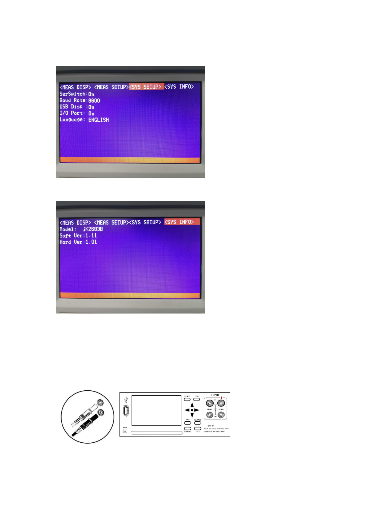
1.3 Name and operation summary of each part..................................................................................5
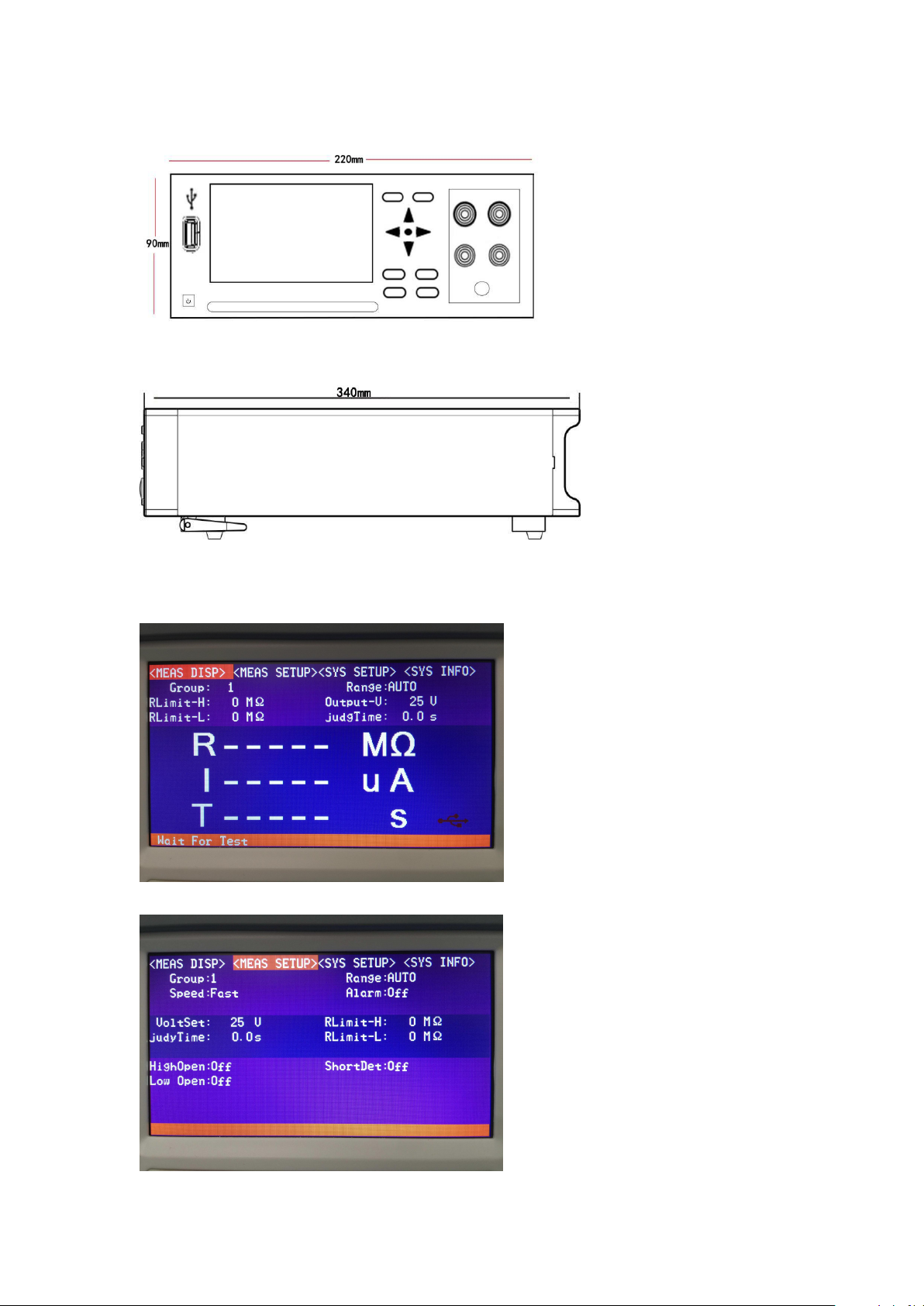
1.4 Dimensions...................................................................................................................................7
1.5 Page Composition........................................................................................................................7
Chapter 2 Preparations Before Testing..............................................................................................8
2.1 Preview of test process.................................................................................................................8
2.2 Basic parameter setting process...................................................................................................9
2.3 Inspection before measurement..................................................................................................10
2.4 Connection of test leads.............................................................................................................10
Chapter.3 Basic Settings...................................................................................................................11
3.1 Setting the test voltage...............................................................................................................11
3.2 Setting the test range..................................................................................................................11
3.3 Setting the test speed..................................................................................................................12
3.4 Comparator function..................................................................................................................13
3.4.1 Sorting mode...........................................................................................................................14
3.4.2 Setting the upper and lower limits and sorting mode..............................................................14
3.5 Sounding mode of sorting results...............................................................................................14
3.6 Short-circuit detection function..................................................................................................15
3.7 Group settings............................................................................................................................16
3.8 Setting the voltage setting..........................................................................................................16
3.9 Test time setting.........................................................................................................................17
3.10 High-end open circuit setting...................................................................................................18
3.11 Low-end open circuit setting...................................................................................................18
3.12 Serial switch setting.................................................................................................................19
3.13 baud rate setting.......................................................................................................................19
3.14 U disk switch setting................................................................................................................20
3.15 I / O port settings......................................................................................................................20
3.16 Display language setting..........................................................................................................21
Chapter 4 Measurement...................................................................................................................22
4.1 Start test......................................................................................................................................22
4.2 Measured value display..............................................................................................................22
4.3 Test Termination.........................................................................................................................22
Chapter 5 PLC Interface...................................................................................................................23
Chapter 6 Parameters.......................................................................................................................24
6.1 General parameters.....................................................................................................................24
6.2 Accuracy.....................................................................................................................................25

1/25
Introduction
Thank you for choosing "JK2683B Insulation Resistance Tester" manufactured by Jinke
Instrument. To get the best performance from your instrument, please read this manual first and
keep it for future reference.
Trademark
Windows and Excel are registered trademarks of Microsoft Corporation in the United States or
other countries.
Verify packaging
When you receive the instrument, check it carefully to make sure that the instrument is not
damaged during transportation. In addition, special inspections of accessories, panel switches and
connectors are required. If it is found that the instrument is damaged or the instrument fails to
operate as written, please contact the dealer or the Jin Ailian Electronic Technology
Representative Office.
To transport the instrument, use the original packaging and a double carton. Damage in transit is
not covered by the warranty.
Packaging items:
JK2683B insulation resistance tester 1
User manual 1
CD 1
1 RS232 cable
HP5521 test lead (optional) 1
Power cord 1
--- JK2683B insulation resistance tester ---
--- 9331 test cable (optional) --

2/25
--- 9800 RS232 communication cable ---
Security Information
The instrument is designed to meet IEC 61010 safety standards and has passed safety tests
thoroughly before shipping. However, improper operation during use may cause injury or death
and damage the instrument. Before use, make sure to read and understand this manual and the
precautions specified in it. Our company does not assume any responsibility for accidents and
injuries not caused by the defects of the instrument itself.
Safety Signs
This manual contains the necessary information and warnings for safe operation of the instrument,
which are necessary to ensure that the instrument is in safe operation. Please read the following
safety precautions carefully before use.
The numbers in this manual show particularly important information, and users should
read it carefully before using the machine. on the instrument indicates that the user must
compare the corresponding topics in the manual before using the corresponding functions.
Represents DC (direct current).
Indicates a fuse.
Ground terminal
Accuracy
We use f.s. (full scale), rdg. (Reading), and dgt. (Resolution) values to define measurement
tolerances, which have the following meanings:
f.s. (maximum display value or measurement range)
Maximum display value or measurement range. This is usually the name of the currently selected
range.
rdg. (read or display value)
The currently measured value and the value displayed on the measuring instrument.
dgt. (resolution)
The smallest displayable unit of a digital tester is to make the digital display display the input
value of the smallest significant digit "1".
Notes on operation
Instrument settings

3/25
Operating temperature and humidity:
0 to 40 ° C, below 80% RH (non-condensing)
Temperature and humidity range to ensure accuracy:
23 ± 5 ° C, below 80% RH (non-condensing)
To avoid malfunction or damage to the instrument, do not place the tester in the following places
Places subject to direct sunlight and high temperatures
It will splash into places where liquid temperature is high and condensation occurs
Exposed to dusty places
Locations subject to corrosive or explosive gases
Places with strong electromagnetic fields and electromagnetic radiation
Places subject to frequent mechanical vibration
Pre-check
Before using the instrument for the first time, verify that it is operating normally and that it is not
damaged during storage or transportation. If you find any damage, please contact your dealer or
your representative.
Before using the instrument, make sure the test leads are well insulated and the
conductors are exposed. If a similar situation occurs, there is a danger of electric
shock when using this instrument, please contact your dealer or Jinailian
Electronic Technology Representative to replace the equipment.
Use of the instrument
To avoid electric shock, do not disassemble the instrument case. There are high
voltage and high temperature parts inside the instrument during operation.
To avoid damaging the instrument, prevent physical impact when moving and
operating the instrument. Extra care should be taken to prevent the instrument
from falling.
The power should be turned off. while stop using the instrument.
Use of the test cable
To prevent electric shock, do not short-circuit the top of the test leads and the
voltage-carrying lines.

4/25
• When performing tests, use the instrument's own test lead option for safety
reasons.
• To avoid damage to the test leads, do not bend or stretch the test leads.
• The probe at the front of the test lead is sharp. Be careful not to get scratched.
Do not hold the cable. Hold the connector.
Measurement considerations:
To avoid electric shock and short circuit, the following procedures must be
followed:
• Do not get the instrument wet or measure with wet hands. Doing so may cause
an electric shock.
• Do not modify, disassemble or repair. Failure to do so may cause fire,
accident, or personal injury.
• Do not place on an unstable stand or tilted place. Failure to do so may result in
injury or malfunction of the unit due to falling or falling over.
• To prevent damage to the instrument, avoid vibration and collision during
handling and use. Pay particular attention to collisions caused by falling.
• To avoid damage to the instrument, do not connect the measurement terminal
to the EX.SW terminal, EX.I / O terminal, or communication terminal.
Chapter 1 Overview
1.1 Introduction
JK2683B insulation resistance tester is an instrument for testing the insulation resistance of
components and equipment. Using constant voltage test method, the voltage output range is 25 ~
1000 V, and the maximum output current is 1.8mA. It also has a contact anomaly detection
function and a short circuit anomaly test function. The fastest test time is up to 50ms. As the
standard output interface of the battery short-circuit tester is an external output interface (EX.I / O),
RS-232C interface, Ethernet interface (LAN), analog output interface (ANALOG OUTPUT) and
U disk interface.
Therefore JK2683B is suitable for use in the field with different connection requirements,
including production and testing lines and laboratories.
1.2 Performance characteristics
□ Appearance
• 3.5-inch high-resolution TFT display for easy operation
• Compact and powerful body
□ Test voltage source
• Test high voltage source using switching power supply principle
• Maximum constant current 1.8mA output
• Voltage adjustment range 25 ~ 1000 V, step 1V
□ Quick test
• The minimum test cycle takes only 50ms

5/25
□ Four-end test
• The instrument can detect abnormal test leads
• The instrument can detect abnormal contact conditions of the measured object (to avoid
misjudgment of open circuit)
□ Short circuit detection
• The instrument effectively detects short-circuit conditions to avoid direct application of high
voltage to break through defective products and cause products
□ Rich interface configuration
• External I / O port
• RS-232C interface
• Ethernet interface
• Analog output interface
• U disk interface
□ Automatic discharge
• After the test, the instrument will automatically discharge
• Non-contact constant current discharge, fast, efficient and reliable
□ Power supply
• 100 ~ 240 V wide power supply
• Automatic recognition of power frequency 50Hz / 60Hz
• Maximum power consumption 15W
1.3 Names and Operations of Each Part
Front
Back

6/25
Side
Bottom
Key Description:
POWER
instrument on / off key
RESET
TEST
PAGE
[Page switch key] Switch [Measurement display] <->
[Parameter Setting] <-> [System Setting] <-> [System
Information]
VOLTAGE
SORTING
EXIT
Arrow keys
[Arrow keys] for selecting menu items or setting values

7/25
1.4 Dimensions
1.5 Page Composition
Measurement page
Parameter setting page

8/25
System settings interface
System Information Interface
Chapter 2 Preparation before testing
2.1 Preview of test process
With the instrument turned off, follow the steps below to prepare for the test.
1. Power off the instrument and connect the test leads
2. Plug in the power cord

9/25
Ensure that the power cord is well grounded, which is conducive to the stability of the test.
3. Turn the power at the rear of the instrument to the "on" state
At this time, the internal power of the instrument has been turned on, and the instrument is in
standby state.
4. Long press the panel power button to turn on the power
In the standby state, the panel power button light is red. Press the panel power button, the power is
turned on, the screen is lit, and the panel button light is green.
5. Set the test parameters (see section 2.2 for details)
6. Test
7. After the test, turn off the power
2.2 Basic parameter setting process
Voltage setting, setting range 25 ~ 1000 V → resistance range setting, 2MΩ / 20 MΩ / 200MΩ /
2000MΩ / automatic range → measurement speed setting, fast and slow → measurement time

10/25
setting, set the test time (voltage output until the sorting output Time) → test mode setting,
continuous mode / failure stop mode / pass stop mode / forced termination judgment mode → set
the beep output mode
2.3 Inspection before measurement
Before use, please confirm that there is no failure caused by storage and transportation, and use it
after checking and confirming operation. If it is confirmed that there is a fault, please contact our
sales outlets.
Confirmation of the instrument and peripheral equipment
Inspection item
Solutions
Is the instrument damaged or
cracked?
Is the internal circuit exposed?
Do not use if damaged, please send it for repair.
Are there any debris such as metal
pieces on the terminals?
When attaching, wipe with a cotton swab or the
like.
Is the outer skin of the test lead
broken or exposed?
Damage may result in unstable measurement
values or errors.
It is recommended to replace the wire with no
damage.
Confirmation at power-on
Inspection item
Solutions
After the power switch at the rear of the
instrument is turned on, observe whether the
power button light on the instrument panel is
on.
When turning on the power, are all displayed in
the order of → model name → measurement
screen?
Please confirm whether the button light is on or
not, otherwise, send it for repair.
If the display is different, there may be a
malfunction in the instrument. Please send it in
for repair.
2.4 Test lead connection method
Warning!
• The test lead port is sharp, being careful not to get scratched.
• For safety, use the test leads supplied with the instrument.
• To avoid electric shock, make sure the test leads are connected properly
There are two ways of testing, one is two-terminal test, and the other is four-terminal test. The
four-terminal test is used to identify test errors caused by abnormal test connection lines or
abnormal test connection.

11/25
Chapter 3 Basic Settings
For testing safety, read this chapter before testing.
Note:
During the test, all keys except the [STOP] key are valid. The user must wait for the test to end, or
press the [STOP] key and send a test stop command to forcibly terminate the test. After the test
process is terminated, the instrument can be set.
3.1 Setting the test voltage
The user can choose between automatic range and manual range.
Note:
When the auto range is set to 30 mΩ or less, a maximum current of 1 A will flow into the
measurement target. Therefore, a maximum power of about 2 W may be applied. If you are
concerned about the following problems due to current measurement, select a smaller
measurement current range.
• The test object is blown (fuse, air pump)
• The measured object becomes hot and the resistance value changes
• The measured object is magnetized, and the inductance changes
If the power of the measured object is within the measurement range of each range, the power is
the resistance value × (measured current). When the measurement range is exceeded, the
maximum open circuit voltage × measured current may be reached.
After confirming the range, connect the object to be measured.
* When connected to the measured object, a maximum inrush current of 5 A will flow. (Settling
time: about 1 ms with pure resistance)
3.2 Set the test range
There are two types of range settings: manual range and automatic range. The automatic range
instrument will automatically select a suitable range for testing according to the value of the
measured resistance.

12/25
Manual range setting:
Enter the parameter setting interface, press the up and down keys to display the range, press the
right key to switch the range, and press the enter key to complete the setting. Even when the auto
range function is turned on, the manual range switching is effective (when the auto range is turned
on and the range is switched manually, the auto range function is automatically turned off).
Range:
AUTO ↔ 2MΩ ↔ 20MΩ ↔ 200MΩ ↔ 2000MΩ
Automatic range setting:
In the measurement interface, press the right button to switch the auto range. When set to auto
range, the [AUTO] mark lights up. When the auto range function is turned off, the [AUTO] mark
is not displayed.
Note:
• If the range is changed while the auto range is ON, the auto range is automatically canceled and
it becomes the manual range.
• If the comparator function is set to ON, the range is fixed and cannot be changed. To change the
range, set the comparator function to OFF or change the range in the comparator setting.
• The auto range may become unstable due to the measured object. In this case, specify the range
manually or increase the delay time. For the measurement accuracy of each range, refer to
"Resistance Measurement Accuracy".
3.3 Setting the test speed
In the parameter setting interface, press the up and down keys to move the cursor to speed, you
can switch the current test speed. The time is 500ms. In the test environment, the electric field
interference is relatively large, or the test is difficult to stabilize, it is recommended to use the slow
test.
Note:
• When the abnormality detection function is turned on, the fast sampling time is extended to
100ms, and the slow sampling time is unchanged at 500ms.
• If the sampling period is 500ms during slow test, if the setting of the test period is less than
500ms, the test result will not be displayed. This requires the test cycle time to be set longer than
the sampling cycle.

13/25
3.4 Comparator function
3.4.1 Sorting mode
There are three sorting modes: [Upper sorting] / [Lower sorting] / [Upper and lower sorting]
For example:
Sorting mode
High
limit
Low
limit
Pass
Failure
Online sorting
100M
-----
<100M
≤100M
Low limit sorting
-----
10M
>10M
≥10M
High and low
limit sorting
100M
10M
10M<test
value<100M
test value≥100M
Or test value≤10M
Setting method:
Sorting
method
Setting method
[High limit
sort]
The high limit input value is valid, the low limit
is closed (----)
[Low limit
sort]
The low limit open input value is valid, the high
limit is closed (----)
[High and low
limit sorting]
Both the high and low limit input values are
valid
Switch on high limit to be valid
Switch on low limit to be valid

14/25
3.4.2 Setting the high and low limits and sorting mode
When the upper limit comparison mode is turned on
1. High limit setting
2. Low limit setting
3.5 Sounding mode of sorting results
1. Press the "PAGE" key to select the parameter setting interface
2. Select the relevant menu item
Press the up and down keys to move the cursor to the beep, press the left and right keys to select
"Close" and "Open" and press the enter key to complete the setting.

15/25
Note:
• [L.FAIL] and [F.FAIL] light up at the same time when the test value and sorting value are out of
the range and no valid judgment can be made.
3.6 Short-circuit detection function
Short-circuit detection function is used to judge whether the DUT is short-circuited before the
insulation test. The high voltage of the test output may burn out the metal defects that cause the
short circuit. If you want to avoid this, you can use the short circuit detection function. The
short-circuit detection voltage is about 2 ~ 4V. When the DUT is a capacitive load, there is also a
charging time. There are also two modes for setting the charging time. One is the automatic mode.
By monitoring both ends of the DUT The voltage changes to determine whether the charge is fully
charged. The other is a fixed charging time。
1. Press the "PAGE" key to select the parameter setting interface
2. Select the relevant menu item
Press the up and down keys to move the cursor to short circuit detection. Press the left and right
keys to select "Close" and "Open". Press OK.
Press the key to complete the setting.
Menu
Meaning
Off
Sorting Ringer Off
Pass
When the test passes
Fail
when the test fail

16/25
Menu
Meaning
Off
Turn off short-circuit detection
On
Turn on short-circuit detection
3.7 Group settings
1. Press the "PAGE" key to select the parameter setting interface
2. Select the relevant menu item
Press the up and down keys to move the cursor to the group. Press the left and right keys to select
the set value. The up and down keys increase or decrease the value. Press OK.
Press the key to complete the setting.
There are 5 groups, Group 1-Group 5.
Press the up and down keys to move the cursor to the group, use the left and right keys to set the
number, and press the enter key to complete the setting.
3.8 Setting the voltage setting
1. Press the "PAGE" key to select the parameter setting interface

17/25
2 Select the relevant menu item
Press the up and down keys to move the cursor to the set voltage. Press the left and right keys to
select the set value.
Press the key to complete the setting.
The voltage measurement range is 25V ~ 1000V. Press the up and down keys to select the setting
voltage, and the left and right keys to select the position for setting the value. The number to be set
blinks. Press the up and down keys to increase or decrease the value.
3.9 Test time setting
Press the "PAGE" key to select the parameter setting interface
1. Select the relevant menu item
Press the up and down keys to move the cursor to the test time. Press the left and right keys to
select the set value. The up and down keys increase or decrease the value and press OK.
Press the key to complete the setting.
The test time range is 0S ~ 999.9S, press the up and down keys to select the setting voltage, and
the left and right keys to select the position of the set value. The number to be set blinks. Press the
up and down keys to increase or decrease the value, and press the confirmation key to complete
the setting.

18/25
3.10 High-end open circuit setting
1. Press the "PAGE" key to select the parameter setting interface
2. Select the relevant menu item
Press the up and down keys to move the cursor to the high-end open circuit. Press the left and
right keys to select "Close" "Open"
Menu
meaning
Off
High-end open circuit closed
On
High-end open circuit open
3.11 Low-end open circuit setting
1. Press the "PAGE" key to select the parameter setting interface
2. Select the relevant menu item
Press the up and down keys to move the cursor to the low-end open circuit. Press the left and right
keys to select "Close" "Open"
Table of contents
Other Jinko Test Equipment manuals