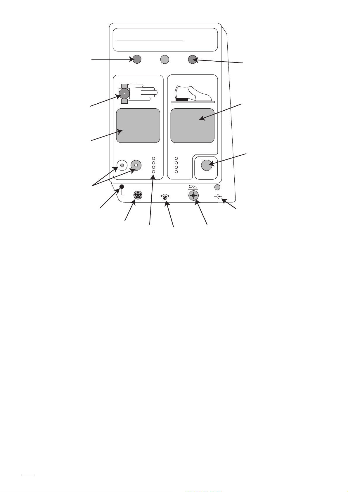
3M 740 User manual

1 / 11
MO 0688-1101
740
wrist strap + shoe tester
3
<>
o.k.
12
3
740 Wrist strap + shoe tester
Operating Instructions MO 0688-1101
Nov 2001

2 / 11 MO 0688-1101
740
wrist strap + shoe tester
3
<>
o.k.
12
MΩMΩ
2 -
5 -
10 -
35 -
- 10
- 35
- 50
- 100
on / off
+
-
Output
R
max
DC 24
•
30 V / 150 mA
II. Declaration of Conformity
The 740 Wrist Strap and Shoe Tester is in
conformity with the regulations of the EMC-
directive 89/336/EWG. The following standards
have been taken into account while designing and
manufacturing the instrument: EN 60204-1/85,
EN 60204-1/91, EN 61010 (Safety),
EN 50082-1/92 and EN 50082-2/92.
I. General
Personnel grounding devices such as wrist straps
and conductive footwear are the primary method
to minimise charge generation on the human
body. They must be able to drain this charge as
rapidly as it is generated.
For this reason, it is important to test wrist straps
and conductive footwear on a regular basis to
ensure they are functioning properly and that the
test results can be recorded
LED for
«too low resistance»
Ground cord
4 mm stud
Contact plate for
wrist strap test
Socket for
wrist strap
Ground Socket
Output signal for external devices
e.g. - data transfer to PC, electrical door
opening system, acoustic signal, etc.
LED Upper limit
selection for wrist
strap and shoe test
Socket for
shoe electrode
Connection for AC/DC
transformer
On / Off switch
Contact plate
for shoe test
LED for
«too high resistance»

3 / 11
MO 0688-1101
R
max
III. Description
The 740 wrist strap and shoe tester is an electronic
test instrument which is easy to operate and
designed to be wall mounted. An AC/DC -
transformer is supplied. The 740 switches off
automatically after non-use for approximately 30
minutes.
The unit consists of two measurement circuits
with an open circuit test voltage of 20 V for wrist
strap and shoe test applications. For wrist strap
and footwear testing, a minimum threshold
resistance of 750 kΩis set internally. The desired
maximum allowable resistance level can be
selected separately for each measurement. If the
resistance of the tested wrist strap or footwear is
within the selected range, the green "o.k."-LED
will illuminate. The red "< " -LED alerts the
operator that the resistance of the tested device is
under 750 kΩ. The red "> "-LED indicates that the
selected maximum resistance is exceeded.
The 740 can be connected to external devices such
as computers (for data recording), electrical door
opening systems, counter or other evaluating
components.
The 740 wrist strap and shoe tester
consists of:
-3.5" - diskette containing instruction manual and
740 daily log sheet
- Base unit
-Data output connector plug
-Wall mounting kit, 3M Dual Lock™fastening
system and template
-Cover for wrist strap plug-in jack
-AC/DC - transformer
-Ground cord
Accessories:
- Shoe electrodes type 741 (single electrode) or
741D (dual electrode) (to be ordered separately).
IV. Operation
Connect the AC/DC - transformer (DC 24-30 V,
150 mA) to the 740 tester.
Note: If you notice a delay in the response time of
the LED illumination please connect the ground
cord supplied to the ground socket of the 740.
Please ensure proper earth ground connection!
Switch the unit on. All LEDs will flash for
approximately 1 s to check their function. Select
the desired upper maximum resistance level for
both the wrist strap and shoe test by using a small
screw driver.
The 741/741D shoe electrode must be connected
if footwear testing is required.

4 / 11 MO 0688-1101
V. Wall Mounting
The enclosed 3M Dual Lock™fastening discs
must be screwed to the wall using the attached
template approximately 1500 mm (5 feet) above
the floor. Drill three holes of 5mm (0.2 in)
diameter at marked locations. Make sure the area
on the 740 in which the Dual Lock™fastening
strips are placed is free of dust and dirt. Attach the
3M Dual Lock™fastening strips to the rear of the
740 tester to the bottom and top in parallel; see
drawing for locations.
For securing on the wall, press the 740 firmly
against the discs. For removal of the 740, lift the
top corners with both hands.
VI. Wrist Strap Test
Put the wrist band on with ground cord attached
and insert the ground cord into the wrist strap
plug-in jack. Depress the metal contact plate and
hold it. One of the indicator-LEDs will illuminate.
An illuminated green LED indicates that the wrist
strap performs within the resistance range of
750 kΩto the upper selected value of 2, 5, 10 or
35 MΩ. If a red "< "-LED is on, the current
limiting resistor in the ground cord is bypassed
and the cord has to be replaced. The red "> "-LED
indicates that the selected resistance range is
exceeded. Check to see if the high resistance is in
the cord, the wrist band or in the contact between
wrist band and the operator’s skin. To check the
resistance of the ground cord, leave the plug end
of the ground cord attached to the tester and
disconnect the snap end from the wrist band.
Connect ground cord snap to the stud in the hand
symbol or press it onto the contact plate and
depress the plate until one of the LEDs is
illuminated.
Rear of the 740
Template
1 500 mm
(5 feet)
If the green LED illuminates
now, the ground cord can be
used.
If the red "> "-LED is lit,
replace the ground cord.
In some cases, high contact resistance between the
skin and wrist band will cause the tester to show a
red ">" - LED condition. This resistance may be
caused by dry skin or the presence of hair in the
wrist area. The use of a skin lotion is
recommended to solve this problem.
If a red ">"- LED condition still exists, replace the
wrist band.

5 / 11
MO 0688-1101
VII. Shoe test
Either the 741/741D shoe electrode must be
connected to the 740 shoe jack.
a) when the 741 single shoe electrode is
used:
If the red "> "-LED is illuminated, clean the soles
of the shoes or check shoe grounding system (heel
ground or toe ground strap) and retest. If, after
cleaning, the red "> "-LED remains lit, replace it
by an appropriate device. If the red "< "-LED is
illuminated, the minimum resistance of the shoes
or shoe grounding system is under 750 kΩ.
An electrical hazard to personnel may exist at the
work place.
b) when the 741D dual shoe electrode is
used:
The dual shoe electrode allows differentiation
between the right and left shoe; giving the right
shoe a preference in indication. This means, if
both shoes or just the right one are out of range,
you will get identical indications as it would be
with the single shoe electrode. If just the left shoe
is out of range, the corresponding red LED will
flash. Consequently, in case of a steadily lit red
LED, you shall clean or remove right shoe first
and retest. If the right shoe is in the "ok"-range
then, you will obtain information about
performance of the left shoe and you can react
accordingly.
The shoe test does not influence the wrist strap
test, therefore the shoes can be tested while the
wrist strap is still connected to the 740 or the wrist
strap can be tested while the operator is standing
on the 741 shoe electrode. Both metal plates shall
not be pressed at the same time.
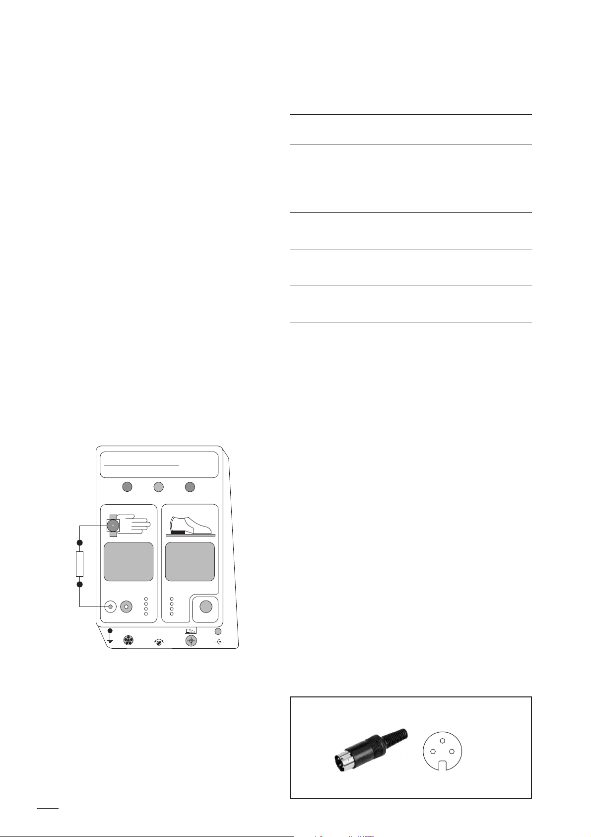
Switch the 740 on. Stand on the applied shoe
electrode. If you are using shoe straps with a
1MΩ- resistor on both feet to be tested with the
741 shoe electrode, you have to test the straps one
after the other, to avoid a red "too low" -
indication. Care must be taken not to put the non-
tested foot on ESD - protective flooring to avoid a
bypass to ground. Depress the metal contact plate
for shoe test until one of the indicator - LEDs
lights up. The green LED indicates that the
resistance of the person through the footwear is in
the range between 750 kΩand the desired upper
maximum level (10, 35, 50 or 100 MΩ).

6 / 11 MO 0688-1101
1
5
6
4
3
2
1
5
6
4
3
2
VIII. Data Output Connector
If you are going to use the data output connector you must follow a test sequence. It must be wrist strap
test first and then the shoe test. If this sequence is not strictly kept, the output at the pins described
on page 7 will be mixed up.
The 740 will provide digital signals (high/low) while testing the personnel grounding devices. These
digital signals can be used for data recording (Example 1) and authorisation control equipment such as
electrical door opening systems (Example 2). The output of the 740 will give you permanently + 5 V at
pin 3 and DC-return at pin 6. The remaining pins 1, 2, 4 and 5 (open collector) will be high
(max. + 30 V/20 mA have to be provided externally) or low (DC-return) while pressing on the contact
plates either for wrist strap or shoe tests. The chart on page 7 shows all of the possible test results and
the corresponding output levels.
Example 1: Output connection for use
with a computer
Example 2: Output connection for use
with a controlling device
Output
connector
Output
connector
Computer
input
Computer
ground
External
voltage
source
max. 30 V
Pin 3
+ 5V
5 kΩ
Pin 1, 2, 4 or 5
Pin 6
Relay
I max. 20 mA
Pin 1, 2, 4 or 5
Pin 6

7 / 11
MO 0688-1101
1
5
6
4
3
2
Data output connector pin status when testing wrist strap/shoe
The sequence for testing must be wrist strap test first and then the shoe test.
Shaded pin indicators will read "hi" if the sequence is reversed or only the shoe tests are
performed.
Data Output Connector
pin 1, 2, 4, 5 - high or low
pin 3 - + 5 V
pin 6 - DC-return
IX. Specifications
Dimension of base unit:
138 mm x 190 mm x 53 mm
(5.25 x 7.5 x 2) inches
Weight:
450 g
(15.75 oz)
Power supply:
external AC/DC - transformer,
DC 24-30 V/150 mA
Accuracy:
±10% of 2, 5, 10, 35 and 50 MΩ-ranges
±20% of 100 MΩ-range
Output:
open collector at pin 1,2, 4, 5
(max. + 30 V/20 mA)
DC-return at pin 6, + 5 V at pin 3
Measurement voltage:
DC (20±1) V (open circuit)
:purewoP
:1tlusertseT:2tlusertseT:3tlusertseT:4tlusertseT
parwtsirw
.k.o
eohs
.k.o
parwtsirw
.k.oton
eohs
.k.o
parwtsirw
.k.o
eohs
.k.oton
parwtsirw
.k.oton
eohs
.k.oton
1nip
ihihiholihihololol
2nip
ihihihih olih olih ol
3nip
ihihihihihihihihih
4nip
ihih olihihihihihih
5nip
ihololihololihihih

8 / 11 MO 0688-1101
740
wrist strap + shoe tester
3
<>
o.k.
12
2 -
5 -
10 -
35 -
- 10
- 35
- 50
- 100
on / off
+
-
Output
R
max
DC 24
•
30 V / 150 mA
750 kΩ
AB
X. Calibration Procedure
The following procedure can be used to determine
if the 740 operates within its specifications.
Please note: The tester has no adjustable
components.
Equipment needed:
1. Resistors
750 kΩ- 120 MΩ, tolerance ±1%
2. 2 leads
as required to connect the reference resistor
a) calibration of wrist strap test circuit:
Connect the reference resistor to the 740 as shown
in the figure below. Switch the 740 unit on. Select
the 2 MΩ-range and use the reference resistors as
indicated in the test table and press contact
plate A.
b) calibration of shoe test circuits:
The 740 Tester can either operate with the single
or dual shoe electrode. They are identified by the
wiring in the 3-pin plug according to DIN 41 524,
type HIRSCHMANN MAS 3100, that connects
the shoe electrode to the 740. For the single shoe
electrode, the cord is connected to pin 1 while
pins 2 and 3 are shunted and grounded.
The dual shoe electrode uses the same plug but
has got the following connections:
pin 1: right shoe electrode
pin 2: open
pin 3: left shoe electrode.
Reference Resistance LED -
resistor range settings Indication
*750 kΩ2 MΩ- range Red
900 kΩGreen
1.8 MΩGreen
>2.2 MΩRed
4.5 MΩ5 MΩ- range Green
>5.5 MΩRed
9.0 MΩ10 MΩ- range Green
>11.0 MΩRed
31.5 MΩ35 MΩ- range Green
>38.5 MΩRed
*This example is used above
The LEDs will indicate as shown below if the 740
performs within specifications. Repeat this
procedure for 5, 10 and 35 MΩ-ranges.

9 / 11
MO 0688-1101
740
wrist strap + shoe tester
3
<>
o.k.
12
2 -
5 -
10 -
35 -
- 10
- 35
- 50
- 100
on / off
+
-
Output
R
max
DC 24
•
30 V / 150 mA
11.1 MΩ
AB
II) calibration of the dual shoe test circuits:
The 740 Tester measures the resistance of both
shoes almost at the same time. The test result for
the circuit of the right shoe has got priority. The
calibration can be either performed with two
reference resistors for both circuits to be checked
at the same time or -corresponding to the single
shoe test - with one reference resistor for one
circuit to be checked and an appropriate bridge
resistor (1MΩe.g.) for the other circuit. For
completion of calibration, the test has to be
repeated with connections of the resistors vice
versa. Follow the instructions for the single
electrode calibration test accordingly.
For the operation with two reference resistors
proceed as follows: Connect one reference resistor
between contact 1 of the socket and the stud and
the other one between contacts 2 and 3. Select the
10 MΩ-range and set the reference resistors as
indicated in the test table and press contact
plate B. The LEDs shall light as shown below.
Repeat this procedure for 35, 50 and 100 MΩ-
ranges.
Right shoe Left shoe
electrode electrode
circuit circuit Signal
OK OK green steadily
high OK > red steadily
low OK < red steadily
OK high > red flashing
OK low < red flashing
high low > red steadily
low high < red steadily
high high > red steadily
low low < red steadily
I) calibration of the single shoe test circuit:
Connect a reference resistor to the 740 between
contact 1 of the socket and the stud as shown
below. Contacts 2 and 3 of the socket shall be
bridged via an appropriate resistor (1MΩe.g.)
Select the 10 MΩ-range and set the reference
resistors as indicated in the test table and press
contact plate B.
The LEDs shall light as shown below. Repeat this
procedure for 35, 50 and 100 MΩ-ranges.
Reference Resistance LED -
resistor range settings Indication
750 kΩ10 MΩ- range Red
900 kΩGreen
9,0 MΩGreen
*> 11,0 MΩRed
31,5 MΩ35 MΩ- range Green
>38,5 MΩRed
45,0 MΩ50 MΩ- range Green
> 55,0 MΩRed
80,0 MΩ100 MΩ- range Green
> 120,0 MΩRed
*This example is used above

10 / 11 MO 0688-1101
raeY/htnoM
emaN 123456789 01112131415161718191021222324252627282920313
WSWSWSWSWSWSWSWSWSWSWSWSWSWSWSWSWSWSWSWSWSWSWSWSWSWSWSWSWSWSWS
1tseT
2tseT
1tseT
2tseT
1tseT
2tseT
1tseT
2tseT
1tseT
2tseT
1tseT
2tseT
1tseT
2tseT
1tseT
2tseT
1tseT
2tseT
1tseT
2tseT
1tseT
2tseT
1tseT
2tseT
1tseT
2tseT
1tseT
2tseT
1tseT
2tseT
1tseT
2tseT
1tseT
2tseT
x
3M 740 Wrist Strap + Shoe Tester Logbook
Example:
Not ok:
ok:
Unit calibrated on:
By:
Next calibration on:
Serial number:
raeY/htnoM
emaN 1234
WSWSWSWS
1tseT
xxxxxx
2tseT
xxxx x
Test parameters:
Wrist Strap (W) Shoes (S)
750 kΩto: 2 MΩ750 kΩto: 10 MΩ
5 MΩ35 MΩ
10 MΩ50 MΩ
35 MΩ100 MΩ

11 / 11
MO 0688-1101
Distributed by:
SJM Eurostat UK Ltd.
Countess Avenue
Stanley Green Trading Estate
Cheadle Hulme, Cheshire SK8 6QS
United Kingdom
Tel: + 44 (0) 161 485 5002
Fax: + 44 (0) 161 485 4678
3M France
Electronic Handling & Protection
Boulevard de l’Oise
95006 Cergy Pontoise Cedex
Tél. : + 33 (0) 1 30 31 68 09
Fax : + 33 (0) 1 30 31 61 81
SAS au capital de 8 400 000 euros -
542 078 555 RCS Pontoise APE 246C -
n°Identification TVA : FR 25 542 078 555 -
CCP n°30041 00001 0143470B020 03 Paris
3
Magnab Eurostat
Skvasta Industriby 16BN
61192 Nyköping
Sweden
Tel: + 46 (0) 155 20 26 80
Fax: + 46 (0) 155 26 98 34
Important notice to purchaser
"Warranty-3M expressly warrants that for a period
of twelve (12) months from the date of purchase,
3M Static Control Products will be free of defects
in materials (parts) and workmanship (labor).
Defects occurring during the warranty period will
be repaired or products will be replaced at 3M’s
option and expense, if 3M receives notice during
the warranty period. Defective products must be
returned to 3M with proof of purchase date.
Warranty exclusions: the foregoing express
warranty is made in lieu of all other product
warranties, express and implied, including fitness
and merchantability. The express warranty will
not apply to defects or damage due to accidents,
neglect, misuse, alterations, operator error, or
failure to properly maintain, clean, or repair
products.
Limit of liability-in no event will 3M or seller be
responsible or liable for special, incidental, or
consequential losses or damages, whether based in
tort or contract. Fulfillment of 3M’s warranty
obligations will be customer’s exclusive remedy
and 3M’s and seller’s limit of liability for any
breach of warrant or otherwise."
Other manuals for 740
3
Table of contents
Other 3M Test Equipment manuals

3M
3M FT-10 User manual

3M
3M FT-30 User manual

3M
3M 701-L User manual

3M
3M Attest Super Rapid Readout Biological Indicator... User manual

3M
3M Charge Analyzer 711 User manual

3M
3M AcoustiCal AC-300 User manual

3M
3M E-A-Rfit User manual

3M
3M LRSM Instruction manual

3M
3M Clean-Trace AQF100 Instruction sheet

3M
3M 101 Series User manual

3M
3M SE-400 Series User guide

3M
3M Dynatel 965AMS-BT User manual

3M
3M Wireless Tire Pressure Monitoring System User manual

3M
3M Clean-Trace UXL100 Instruction sheet

3M
3M Dynatel 945DSP User manual

3M
3M 900AST Series User manual

3M
3M 701 User manual

3M
3M 746 User manual

3M
3M 740 User manual

3M
3M Petrifilm Instruction sheet