JJM Boiler Works JM-2 Owner's manual

Condensate
neutralizing
tubes
Installation
Operation &
Maintenance
Models: JM-2 & JM-3
series
JJM Boiler Works, Inc.
69 Ferry Street - Units 17-20
Easthampton, MA 01027
Phone 413-527-1893
web: www.jjmboilerworks.com
Revised - January, 2014

Read before proceeding
Failure to comply with these guidelines could result
in severe personal injury, death or substantial
property damage.
Neutralizer and lines must be wet
• Beforeoperatingtheboilerorfurnace,lltheJMtubeand
trapswithtapwater.NEVERoperatewithtubesorP-traps
dry.
Application restrictions
• Flue gas condensing boilers, furnaces, and flue pipe conden-
sate drains only.
• DO NOT exhaust flue gases through JM tubes, they are not
rated for boiler or furnace flue gases. Operating JM tubes
as exhaust vents can cause injury or death from carbon
monoxide.
• Gas traps must be installed between the boiler, vent drains,
and furnace condensate outlet and the inlet of all JM tubes.
• JM tubes must be installed below system P-traps, boiler,
furnace, and breaching condensate drains.
Combined piping options
Flue pipe condensate drains
• Boiler/furnace condensate drain and flue condensate drain
can be common piped to a neutralizer tube ONLY if the
boiler/furnace is individually vented (NOT connected to a
common vent system).Also, the flue pipe must be terminated
so rain water cannot enter the flue pipe.
• DO NOT connect any flue pipe condensate line to a neutral-
izer tube that serves more than one boiler. Consult factory.
Boiler/furnace condensate line common piping
• DO NOT combine vent condensate drain lines and boiler/
furnace condensate lines if appliances are common vented.
Use a separate JM-series tube for each application. For
individually-vented appliances, vent and condensate drain
lines can be combined.
Recharge tubes regularly
• Tubes should be recharged when pH level moves below 5.0
The pH should be checked regularly (at least twice during the
first year of operation) to determine the required recharging
schedule.
• This may require recharging as often as twice per year for
high-usage systems, such as boiler systems equipped with
indirect water heaters.
• Boiler/furnace applications for space heating only (no DHW)
may require recharging only once per year or when PH falls
below 5.
What is pH?
The pH measurement of a fluid is an indicator of the acidity
or alkalinity. Neutral fluids have pH of 7.0. Acid fluids have pH
below 7. And alkaline fluids have pH above 7 (up to 14). The pH
can be easily measured using litmus paper.
Condensate pH from condensing boilers and furnaces range from
1.9 - 3.5pH. The condensate pH needs to be increased (made
more neutral) to prevent possible damage to cast iron soil pipe,
ABS pipe, septic tanks, plants, wastewater treatment plants and
other materials handling waste water.
JM-series condensate neutralizing tubes
increase pH (reduce acidity).
JM-series residential/commercial flue-side condensate neutral-
izing tubes & tanks are designed to raise the pH level of the
condensate discharged by high-efficiency boilers and warm air
furnaces.
Each increase of 1.0 in pH is a 10-times decrease in acidity. The
pH of condensate is increased by approximately 1.0 to 3.0 after
passing through neutralizing tubes & tanks. (This is a reduction
in acid concentration of from 10 to 1000 times.)
Applying JM-series neutralizing tubes
Condensate can be collected from flue ways and boiler/furnace
condensate trap outlets. See WARNING section at left for guide-
lines on application.
Match neutralizing tubes to boiler/furnace ratings. Use multiple
tubes if needed to handle the load.
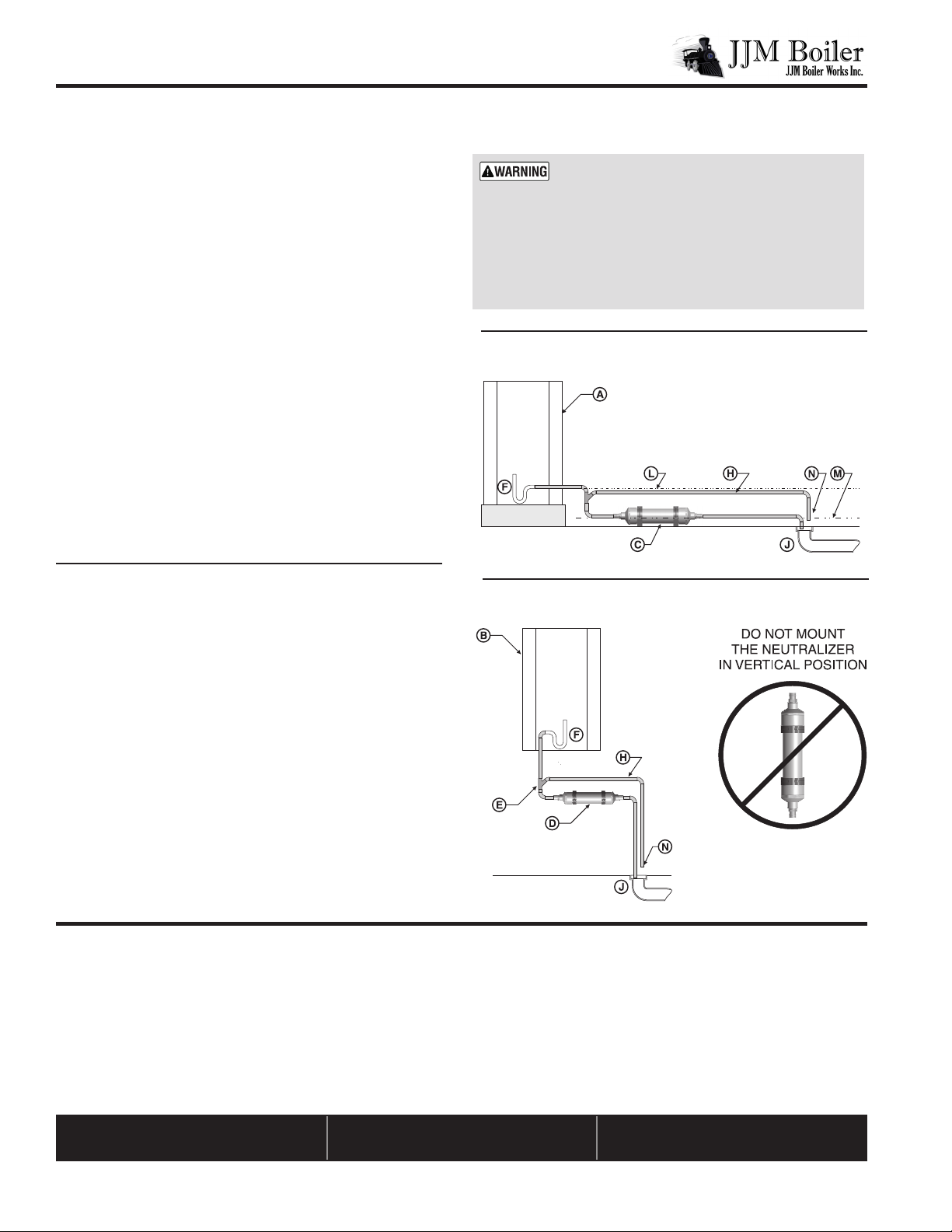
Locate the neutralizing tube below the condensate connection
and slightly above the floor drain or inlet to a condensate pump
reservoir (if used).
Follow the guidelines in this manual, the boiler/furnace manual
and all applicable local codes when installing, using and main-
taining JM-series condensate neutralizing tubes.
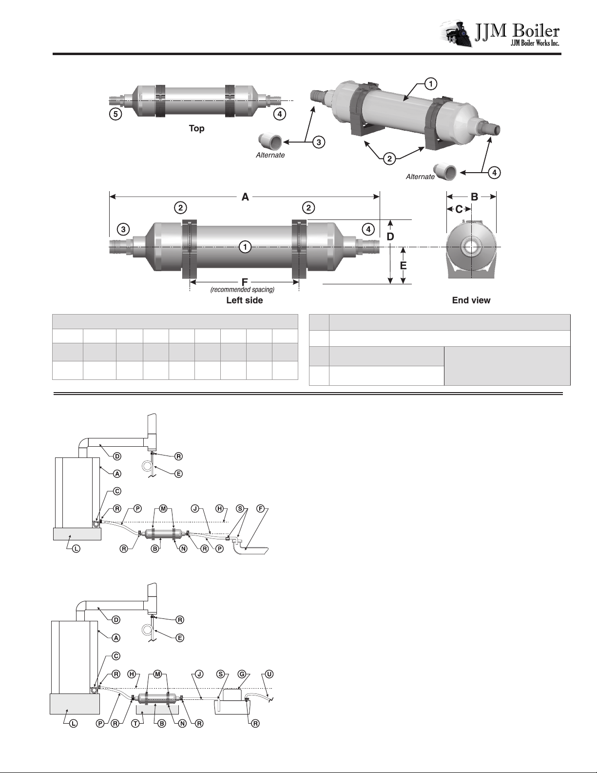
Installation sequence
1. Before installing boiler or furnace, determine if a mounting pad will
be needed to elevate the boiler or furnace so that the condensate con-
nection will be above bottom of the JM tube OUTLET. See Figure 2
or Figure 3. If needed to obtain the proper elevation relative to a
condensate pump reservoir (when used — see Figure 3).
2. Connect PVC piping from appliance or breaching drains to P-traps
and then from P-trap outlets to either one of the two JM tubes.
3. Connect the JM tube outlet to house drain or condensate pump.
4. Use Teflon tape on all threaded plastic fittings.
5. NOTE — Always consult the local authority regarding any require-
ments concerning flue gas condensate handling codes.
JMseries Condensate Neutralizing Tubes –– Installation/Operation & Maintenance
2
Overview

Installation
Figure 1 JM-series condensate neutralizing tubes – features and dimensions
JMseries Condensate Neutralizing Tubes –– Installation/Operation & Maintenance
3
RATINGS & DIMENSIONS (in inches)
Model MBH GPH A B C D E F
JM-2 150 2 10.5 2.75 1.375 3.5 1.875 6.5
JM-3 300 3 19.5 2.75 1.375 3.5 1.875, 9.5
1PVC tubing lled with 3
/
8” limestone and 97% MgO Pellets
2Clamp-on support brackets
3Condensate outlet hose barb
tting ¾” hose barb x ½” NPT — or —
¾” PVC x ½” NPT (both supplied)
4Condensate inlet hose barb
tting
Figure 2 JM-series tube with oor drain, typical
Figure 3 JM-series tube with condensate pump, typical
A Condensing boiler or furnace
B Condensate neutralizing tube (or multiple tubes piped in parallel)
C Boiler/furnace condensate trap connection
D Boiler/furnace vent
E Vent condensate trap, when used — Install a trap as shown. Connect
the tubing to a separate JM tube if appliances are common vented. For
individually-vented appliances, the vent condensate drain can be con-
nected to the appliance condensate drain line.
F Drain or sump
G Condensate pump
H Bottom of boiler/furnace condensate outlet — MUST be ABOVE
condensate pump inlet connection
J Bottom of JM tube condensate outlet
L Mounting pad or structural platform, when required to elevate boiler
condensate drain as needed
M Mounting clamps
N Mounting clamps must be secured to the mounting surface
P Plastic tubing or PVC pipe — When using PVC pipe, remove the JM
inlet and outlet hose barb fittings and replace with threaded PVC fit-
tings. Include unions in the piping to allow removal of the JM tube for
inspection and service. — Secure pipe or tubing in place. — Protect
with a shield if necessary if routed through traffic areas.
R Use hose clamps at all connections when using plastic tubing.
S Condensate drain termination at floor drain (or condensate pump
reservoir inlet) — secure in place with clamps. — Follow instructions
for condensate pump.
T Elevate the JM tube on a structural base if necessary for the outlet to be
raised.
U Route condensate discharge line from to appropriate drain location.

A Condensing boiler or furnace, floor-mounted type
B Condensing boiler or furnace, wall-mounted type
C JM neutralizing tube floor-mounted (or multiple tubes piped in
parallel)
D JM neutralizing tube wall-mounted (or multiple tubes piped in
parallel)
E Y-fitting, 3/4: PVC minimum – locate a minimum of 2 inches above
the neutralizing tube and so the overflow line is below the bottom of
appliances condensate drain connection (item L)
F Appliance condensate trap/condensate drain connection
H Overflow drain line (terminate so flow from line is easily seen)
J Floor drain, sump or condensate pump reservoir
L Bottom of appliance condensate drain connection – all condensate
piping and components must be below this level
M Bottom of JM neutralizer tube outlet connection
N Terminate the overflow line above the drain location so any flow
from the line is easily visible
JMseries Condensate Neutralizing Tubes –– Installation/Operation & Maintenance
JJM Boiler Works, Inc.
69 Ferry Street - Units 17-20
Easthampton, MA 01027
Phone 413-527-1893
web: www.jjmboilerworks.com
Inspect frequently
Installer — Instruct the building owner to
frequently inspect the JM neutralizer and
all condensate connections. The owner
must notify a qualified technician if any
problems are noticed.
Maintenance
4
OUTDOOR INSTALLATIONS — provide and install
electric heat tape on the condensate drain lines
and around the JM tube to prevent possibility
of neutralizer tube damage or line blockage due
to freezing. Failure to comply with the following
guidelines could result in severe personal injury,
death or substantial property damage.
Recharge as required
When pH tube or tank outlet falls below
5PH. Local codes may have different
requirement, check with local authority.
Replacement parts
Contact your local wholesaler or manu-
facturer’s representative for replacement
parts.
Dealer listing at www.jjmboilerworks.com
Figure 4 Y-tting by-pass with oor-mounted boiler
(see legend at left)
Figure 5 Y-tting by-pass with wall-mounted boiler
(see legend at left)
Installation (continued)
Piping Options
Overow by-pass piping
See Figure 4 and Figure 5 for installation with a y-fitting for
an overflow by-pass line.
Locate the overflow discharge so flow can be easily seen. Instruct
the owner to notify the service technician immediately if
ow through the overow line is frequent or steady.
Make sure the installation complies with all local code
requirements.
Piping for multiple boilers/furnaces
Use separate neutralizer for common vent drain.
As stated on page 2, do not connect a flue pipe condensate
line to the to the same neutralizer as used for a boiler/furnace
unless the boiler/furnace is individually vented, the vent will
not allow rain water to enter the flue pipe, and no other
appliance is connected to the same neutralizer tube.
Legend for Figure 4 and Figure 5
Revised - January, 2014
This manual suits for next models
1
Other JJM Boiler Works Boiler Supplies manuals
Popular Boiler Supplies manuals by other brands

Immergas
Immergas Victrix Superior KW X Warnings and instruction sheet

Riello
Riello Tau Unit Oil V70 240 instruction manual

REMEHA
REMEHA rematic 2945 C3 K Assembly instruction

Crown Boiler
Crown Boiler AM4 installation instructions

IBC
IBC SL 80-399 instruction manual

Immergas
Immergas 3.020934 Warnings and instruction sheet