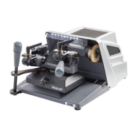
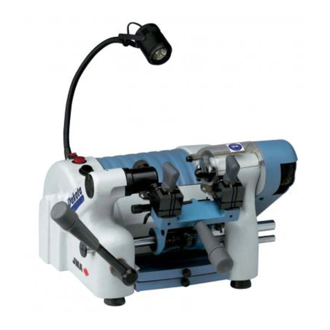
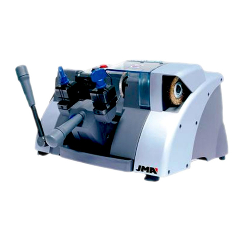
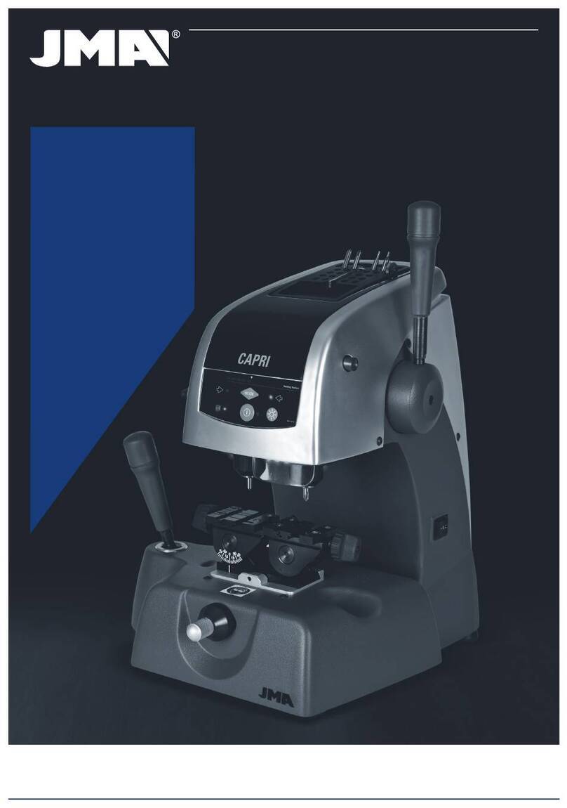
JMA CAPRI User manual

MÁQUINA DUPLICADORA CAPRI
MANUAL DE INSTRUCCIONES
KEY CUTTING MACHINE CAPRI
INSTRUCTION MANUAL
MACHINE DUPLICATRICE CAPRI
NOTICE D’UTILISATION
DUPLIZIERMASCHINE CAPRI
BEDIENUNGSANLEITUNG
NØGLEMASKINE CAPRI
BRUGSANVISNING
MÁQUINA DUPLICADORA CAPRI
MANUAL DE INSTRUÇÕES
CAPRI (V.02)


español
CAPRI
MANUAL DE INSTRUCCIONES
MÁQUINA DUPLICADORA

español
1.- PRESENTACIÓN Y ASPECTOS GENERALES
1.1 GENERALIDADES
1.2 TRANSPORTE Y EMBALAJE
1.3 ETIQUETA IDENTIFICADORA
2.- CARACTERÍSTICAS DE LA MÁQUINA
2.1 FAMILIAS DE LLAVES
2.2 ACCESORIOS
2.3 ALMACÉN DE HERRAMIENTAS
2.4 CIRCUITO ELÉCTRICO
2.5 DATOS TÉCNICOS
2.6 ELEMENTOS PRINCIPALES DE LA MÁQUINA
2.7 COMPONENTES Y PARTES FUNCIONALES
2.7.1 CAMBIO DE FRESA Y DE PALPADOR (21)
2.7.2 BLOQUEO DEL CARRO EN EL FIN DEL RECORRIDO DEL EJE “Y”
2.7.3 MORDAZA (6)
2.7.4 MUELLEO DEL PALPADOR (11)
2.7.5 MUELLEO Y BLOQUEO DEL CARRO EN EL EJE “X” (5 AND 4)
2.7.6 PALANCA DE APOYO PARA LLAVES TUBULARES
2.7.7 VELOCIDAD DE FRESA (17)
2.7.8 DISPLAY-TECLADO (1)
2.7.9 REGULACIÓN VERTICAL DEL PALPADOR (15)
2.7.10 CONTROL DE LA FUERZA DE DUPLICADO
3.- CIFRADO
3.1 PROCESO DE CIFRADO
3.2 CIFRADO DE LLAVES
3.2.1 LLAVES KA-2, KA-3 Y KA-4.
3.2.2 LLAVE KE-1.
3.2.3 LLAVE SEA-1.
3.2.4 LLAVES OP-WH.P Y OP-WY.P
3.2.5 LLAVES ME-4.P, ME-6.P, ME-7.P, ME-8.P, ME-11.P Y ME-12.P
3.2.6 LLAVES TUBULARES
3.2.7 LLAVES CISA
3.2.8 LLAVES HU-HAA
3.2.9 LLAVES REGATA DE PEQUEÑO ESPESOR
3.2.10 LLAVES TE-12P
3.2.11 LLAVES FIC-2 Y FIC-3
3.2.12 LLAVES WIN-1D, WIN-2D, WIN-3D, WIN-4D
3.2.13 LLAVES JIS-4.P
3.2.14 LLAVE FO-6.P
3.2.15 LLAVE MCM-10
3.2.16 LLAVE TE-T60 Y TE-T-80
4.- MANTENIMIENTO
4.1 SUSTITUCIÓN DE LAS GARRAS DE LA MORDAZA
4.2 REGLAJE DE LAS GARRAS
4.2.1 REGLAJE NORMAL
4.2.2 REGLAJE DE PRECISIÓN
4.3 SUSTITUCIÓN DE LOS FUSIBLES
4.4 TENSADO Y SUSTITUCIÓN DE LA CORREA
4.5 SUSTITUCIÓN DEL MOTOR
4.6 SUSTITUCIÓN DEL DISPLAY-TECLADO
4.7 SUSTITUCIÓN DE LA TARJETA ELECTRÓNICA DE CONTROL
4.8 SUSTITUCIÓN DE LA TARJETA DE POTENCIA Y DEL DISYUNTOR
5.- SEGURIDAD
6.- ELIMINACIÓN DE DESHECHOS
6.1 EMBALAJE
6.2 VIRUTA
6.3 MÁQUINA
7.- TABLA LLAVE-FRESA-PALPADOR-INCLINACIÓN-ADAPTADOR
8.- EXPLOSIONADO

español
1.- PRESENTACIÓN Y ASPECTOS GENERALES
1.1 GENERALIDADES
La máquina duplicadora CAPRI ha sido diseñada teniendo en cuenta las normas de
seguridad vigentes en la C.E.E.
La seguridad del personal involucrado en el manejo de este tipo de máquinas solo se
consigue con un programa bien diseñado en seguridad personal, como la implantación
de un programa de mantenimiento y el seguimiento de los consejos recomendados así
como el cumplimiento de las normas de seguridad que contempla este manual.
Aunque la instalación de la máquina no presenta ninguna dificultad, es preferible que
no intente instalar, ajustar o manipular la misma sin leer primeramente este manual.
La máquina sale de nuestra fábrica lista para el uso y solo necesita operaciones de
calibrado para los útiles que se van a utilizar.
1.2 TRANSPORTE Y EMBALAJE
La máquina se presenta en una caja de cartón robusta protegida con espuma de emba-
laje de las siguientes dimensiones:
Ancho = 520 mm; Alto = 650 mm; Profundidad = 575 mm
Peso máquina más embalaje = 30 Kg.
Cuando desembale la máquina, inspecciónela cuidadosamente por si hubiese sufrido
algún daño en el transporte.
Si encuentra alguna anomalía, avise inmediatamente al transportista y no haga nada
con la máquina hasta que el agente del transportista haya realizado la inspección co-
rrespondiente.
Para desplazar la máquina de un lugar a otro, coger la máquina por su base, y no por
otras partes.
1.3 ETIQUETA IDENTIFICADORA
La máquina duplicadora CAPRI está provista
de una etiqueta identificadora, con especi-
ficación del número de serie o matrícula de
máquina, nombre y dirección del fabricante,
marca CE y año de fabricación.
2. - CARACTERÍSTICAS DE LA MÁQUINA
La máquina CAPRI es una duplicadora de gran robustez y precisión, que se caracteriza
por las múltiples posibilidades de sujeción que permite su mordaza, sin necesidad de
utilizar postizos ni adaptadores.
Incorpora un novedoso sistema de control de fuerza, que hace aumentar la precisión
del duplicado.
2.1 FAMILIAS DE LLAVES
La máquina CAPRI duplica entre otras, los siguientes tipos de llaves:
- Llaves de puntos
- Llaves de regata
- Llaves tubulares
- Llaves CISA
- Llaves HU-HAA
- Llaves JIS-4.P
- Llaves FO-6.P
2.2 ACCESORIOS
La máquina se suministra con una serie de accesorios para su uso y mantenimiento.
Todos estos accesorios pueden alojarse en el almacén de herramientas del que dispone
la máquina.
- 2 fusibles (alojados en la parte inferior del almacén de herramientas)
- Llaves allen de 5, de 3 y de 2.5
- 1 Llave allen especial de brazo corto de 1,5.
- 2 chapas de tope punta
- 2 ejes para el reglaje de las garras.
- 2 Adaptador para la llave tubular CHI-1T
- Fresas: F-1 y F-13
- Palpadores: T-1 y T-13.
2.3 ALMACÉN DE HERRAMIENTAS
La máquina dispone de un almacén de herramientas, que va montado en la parte supe-
rior de la máquina. Ofrece la posibilidad de extraerlo y apoyarlo directamente sobre una
mesa (de esta manera se obtiene un espacio extra en la parte superior de la máquina,
aprovechable para depositar llaves, accesorios, etc…).
2.4 CIRCUITO ELÉCTRICO
Los componentes principales del circuito eléctrico y electrónico son los siguientes:
1. Toma de corriente.
2. Placa de conexiones.
3. Interruptor de 3 posiciones.
4. Transformador.
5. Motor.
6. Display-teclado.
7. Tarjeta de control.
8. Fresa.
9. Palpador.
10. Mordaza.
11. Diodos LED de Iluminación.
12. Sensor de fuerza.
Ver Figura 2
2.5 DATOS TÉCNICOS
Motor: Monofásico 400 W. ,230 V - 50 Hz (Opcional: Monofásico 400W, 110V – 60Hz)
Fresa: HSS (Opcional: Metal duro)
Velocidad fresa: 6.000 y 11.000 r.p.m.
Mordazas: De dos caras de amarre y basculantes 0 / 45 º
Desplazamiento: En tres ejes con guías de rodillos de precisión.
Cursos útiles: Eje X = 71 mm; eje Y = 62 mm; eje Z = 40 mm
Iluminación: Diodos Led
Dimensiones: Ancho = 430 mm, Profundidad = 385 mm y Alto = 485 mm
Peso: 25 Kg
2.6 ELEMENTOS PRINCIPALES DE LA MÁQUINA
1.- Display-teclado
2.- Carro porta mordazas (ejes X – Y)
3.- Palanca de accionamiento de los carros, ejes x – y
4.- Pomo de bloqueo del carro porta mordazas, eje x
5.- Rueda accionamiento del sistema de muelleo del carro, eje x
6.- Mordaza
7.- Palanca de bloqueo del giro de las mordazas
8.- Pomo de la mordaza
9.- Cabezal (eje Z)
10.- Palanca de accionamiento y bloqueo del cabezal, eje z
11.- Maneta de muelleo del palpador
12.- Portaherramientas
13.- Fresa
14.- Palpador
15.- Rueda de regulación de la altura del palpador
16.- Interruptor general
17.- Selector de velocidad del motor (2 velocidades)
18.- Leds de iluminación
19.- Protector de virutas
20.- Almacén de herramientas
21.- Pulsador de bloqueo de la fresa
Ver figura 3
2.7 COMPONENTES Y PARTES FUNCIONALES
2.7.1 CAMBIO DE FRESA Y DE PALPADOR (21)
Para soltar la fresa, hay que accionar el pulsador de bloqueo de la fresa al mismo
tiempo que con la mano hacemos girar el portaherramientas.
Después de extraer la fresa a reemplazar, introducir la nueva fresa y amarrarla en el
portaherramientas, asegurándonos de que su extremo hace tope en el interior del por-
taherramientas.
El palpador se reemplaza de la misma manera que la fresa. La única diferencia a tener
en cuenta es que el giro del palpador siempre se encuentra bloqueado internamente.
2.7.2 BLOQUEO DEL CARRO EN EL FIN DEL RECORRIDO DEL EJE “Y”
Con el objetivo de que el carro no se desplace en la dirección “Y”, durante el tiempo
que el duplicador está amarrando las llaves en la mordaza, se ha dotado al carro de un
bloqueo momentáneo en esta dirección.
Para accionar este bloqueo, basta con desplazar el carro hasta su tope de recorrido en
la dirección hacia el duplicador.
Para desactivar este bloqueo, basta con desplazar el carro hacia delante, haciendo un
poco de fuerza.
2.7.3 MORDAZA (6)
Las prestaciones de la mordaza de la duplicadora CAPRI son superiores a las de una
máquina normal del mercado, al disponer de dos caras de amarre independientes. Ade-
más, las mordazas se pueden bloquear en cualquier posición de giro entre 45º 0º -45º.

español
2.7.4 MUELLEO DEL PALPADOR (11)
Existen dos maneras diferentes de utilizar el palpador, en función del trabajo que vaya
a realizarse:
- Palpador con muelleo. El muelleo del palpador se utiliza única y exclusivamen-
te para el cifrado de llaves de puntos.
- Palpador bloqueado. El palpador bloqueado se utiliza para realizar operaciones
de duplicado con avance del carro. En general, para el cifrado de llaves de regata.
Para activar o desactivar el muelleo del palpador, basta con hacer girar 180º (media
vuelta) la maneta de muelleo del palpador.
Cuando se activa el muelleo del palpador, la punta del palpador se sitúa ligeramente
por debajo de su posición de ajuste respecto de la fresa. Esta posición del palpador nos
permite que se pueda introducir suavemente en el agujero de la llave original, antes
de que la fresa comience el fresado de la llave a duplicar. De esta manera se evitan
vibraciones y desplazamientos bruscos del carro.
Para conocer en cualquier momento el estado del palpador (con muelleo o bloqueado),
disponemos en el display-teclado de la máquina de un indicador que nos ofrece esta
información. Si el piloto está iluminado, el muelleo está activado. Por el contrario, si el
piloto está apagado, el palpador está bloqueado.
2.7.5 MUELLEO Y BLOQUEO DEL CARRO EN EL EJE “ X “ (5 Y 4)
El sistema de muelleo del carro en el eje “X”, recomendamos utilizarlo para realizar los
fresados laterales de las llaves de regata.
El bloqueo del carro en el eje “X “, recomendamos utilizarlo para realizar fresados o
puntos en línea recta.
2.7.6 PALANCA DE APOYO PARA LLAVES TUBULARES
La máquina duplicadora CAPRI dispone en su lateral superior izquierdo, de una palanca
abatible que ayuda a hacer más cómodo el duplicado de las llaves tubulares, regatas,
etc…., al disponer de un punto de apoyo para la mano que acciona la palanca de
traslación de los carros.
2.7.7 VELOCIDAD DE LA FRESA (17)
La máquina dispone de un selector de velocidad situado en su lateral derecho y que
permite seleccionar la velocidad de giro de la fresa. Como concepto general puede
decirse que la velocidad de giro depende del material de la fresa:
- Posición I: Para trabajar con fresa de HSS (6.000 rpm)
- Posición II: Para trabajar con fresa de METAL DURO (11.000 rpm)
- Posición O: Fresa parada.
2.7.8 DISPLAY-TECLADO (1)
Tecla ON-OFF.
Presionándola, las funciones del display-teclado pasan a modo ACTIVO. Junto a la tecla
aparecerá una luz verde.
Presionándola de nuevo, el display-teclado pasa a un estado de “STAND-BY”. Junto a
la tecla aparecerá una luz roja.
Tecla ILUMINACION.
Presionándola, se encienden los diodos de iluminación (si están apagados) o se apagan
si están encendidos.
Esta tecla funciona independientemente del estado de la tecla “ON-OFF”.
Indicador MUELLEO.
Si la luz azul está encendida, nos indica que al palpador está en estado de MUELLEO
ACTIVADO.
Si la luz azul está apagada, nos indica que el palpador está BLOQUEADO (muelleo de-
sactivado).
Tecla MODE.
Esta tecla sirve para activar-desactivar el funcionamiento del sistema de regulación
vertical del palpador.
Indicadores REGLAJE DEL PALPADOR.
La luz de la izquierda se enciende cuando el palpador está tocando la llave.
La luz de la derecha se enciende cuando fresa está tocando la llave.
Indicador visual de FUERZA.
Nos indica la fuerza óptima a realizar durante el duplicado.
NOTA: El sistema de control de fuerza, además del indicador visual también dispone
de un indicador sonoro que nos avisa mediante un pitido cuando hemos alcanzado la
fuerza óptima de duplicado. Este indicador sonoro se puede activar-desactivar pulsando
al mismo tiempo las teclas MODE y ON-OFF.
2.7.9 REGULACIÓN VERTICAL DEL PALPADOR (15)
Por cada cambio de fresa-palpador, debe realizarse la regulación vertical del palpador.
Para poder utilizar el sistema electrónico de regulación vertical del palpador, es nece-
sario que el display-teclado esté activo (cuando está activo, aparece una luz de color
verde al lado de la tecla ON-OFF).
Estando el display-teclado activo, es posible activar-desactivar el sistema electrónico
de regulación vertical del palpador, pulsando la tecla MODE.
Para realizar el reglaje vertical del palpador, actuar de la siguiente manera:
• Amarrarlafresayelpalpadorensuscorrespondientesportaherramientas.
Asegurarse de que han quedado amarrados, haciendo tope hacia arriba.
• Amarrardosllavesigualesenlasmordazasdelamáquina.
• Quitarelmuelleodelpalpador(palpadorbloqueado).
• Bajarelcabezal,hastaapoyarlafresayelpalpadorsobrelasllavessituadasen
las mordazas. Entonces, se dará una de las siguientes tres situaciones:
AZUL IZQUIERDA. Si únicamente se enciende la luz de la izquierda, indica que
el palpador está tocando la llave, pero la fresa no. Por lo tanto, que hay que girar
la rueda de regulación del palpador hacia la izquierda, hasta que se enciendan las
dos luces de reglaje.
AZUL DERECHA. Si únicamente se enciende la luz de la derecha, indica que la
fresa está tocando la llave, pero el palpador no. Por lo tanto, que hay que girar la
rueda de regulación del palpador hacia la derecha, hasta que se enciendan las dos
luces de reglaje.
AZUL IZQUIERDA Y DERECHA. Indica que tanto la fresa como el palpador, están
tocando sus respectivas llaves. Esto quiere decir que la altura del palpador está
reglada.
NOTA IMPORTANTE: Al realizar el reglaje de altura del palpador, hay que tener en
cuenta el tipo de llave que vamos a duplicar. Si se trata de una llave de REGATA, hay
que aplicar muy poca fuerza a la palanca de accionamiento del cabezal (que no se
encienda ninguna luz del indicador visual de fuerza). En cambio, si se trata de una llave
de PUNTOS, se tienen que encender las dos luces azules de reglaje, al mismo tiempo
que el indicador de fuerza indica la fuerza ideal de duplicado para llaves de puntos (para
ello, hay que ejercer una ligera fuerza sobre la palanca de accionamiento del cabezal).
2.7.10 CONTROL DE FUERZA DE DUPLICADO
La máquina CAPRI dispone de un revolucionario sistema de control de fuerza de dupli-
cado. Se trata de un sistema patentado, que a la hora de duplicar llaves de PUNTOS,
nos indica la fuerza óptima a realizar sobre la palanca de accionamiento del cabezal.
Para ello, dispone de dos indicadores:
Indicador visual. La fuerza óptima de duplicado se alcanza cuando la línea de
luces llega a la flecha blanca.
Indicador sonoro. Cuando la línea de luces llega a la flecha blanca, la máquina
emite un pitido. Este indicador sonoro, se puede activar-desactivar pulsando al
mismo tiempo las teclas MODE y ON-OFF.
Este sistema de control de fuerza de duplicado nos permite obtener llaves de PUNTOS
con una gran precisión. Duplicaremos los agujeros de la llave exactamente con la mis-
ma fuerza con la que hemos reglado la altura del palpador. De esta manera se obtiene
la máxima precisión en el duplicado de llaves de PUNTOS.

español
3.- CIFRADO
3.1 PROCESO DE CIFRADO
• Enciendalamáquinaaccionandoelinterruptorgeneralsituadoenlapartetrasera
derecha de la máquina.
• Paramejorarlavisibilidaddelazonadetrabajo,activelailuminaciónaccionando
el interruptor situado en el display-teclado.
• Conayudadelatablaqueseincluyeenelpresentemanual,seleccionarlafresay
el palpador necesarios para cifrar la llave.
• Cambiarlafresayelpalpador.
• Bloquearmomentáneamenteelcarroenelfinderecorridodeleje“Y”.
• Amarrarlallaveoriginalenlaparteizquierdadelamordaza,ylallaveacifraren
la parte derecha. A la hora de amarrar las llaves, hay que tener en cuenta los siguientes
detalles:
- TOPE DE LA LLAVE. Puede tratarse de una llave de “tope-cuello” (Fig. 4.A),o de
“tope-punta” (Fig. 4.B).
- ADAPTADOR. En algún modelo de llave muy concreto, puede ser necesaria la
utilización de un adaptador.
- INCLINACIÓN. Algunas llaves tienen los puntos inclinados, por lo que será nece-
sario girar la mordaza.
• Hacerlaregulaciónverticaldelpalpador.
• Activarlossistemasquesimplificaneltrabajodeduplicado:
- PALPADOR: Activar o desactivar el muelleo del palpador, en función del tipo de
llave a cifrar.
- CARRO: En función del modelo de llave, puede ser interesante activar el muelleo
del carro, o el bloqueo del carro en la dirección “X”.
- APOYO: en función del modelo de llave, puede ser interesante utilizar la palanca
de apoyo para llaves tubulares.
• Ponerenmarchaelgirodelafresa,eligiendopreviamenteunadelasdosveloci-
dades disponibles.
• Procederalcifradodelallave.Silallaveesdepuntos,utilizarlaayudadelsistema
de “control de fuerza de duplicado”.
3.2 CIFRADO DE LLAVES
3.2.1 LLAVES KA-2, KA-3 Y KA-4.
• Dependiendodelmodelodellaveaduplicar,seutilizaunaparejafresa-palpador
diferente. Mirar en la tabla.
• Elamarredelallaveenlamordazaserealizahaciendo“topecuello”.
• Dependiendodelmodelodellaveaduplicar,esnecesariogirarlasmordazassegún
el ángulo requerido. Mirar en la tabla.
• Esprecisoactivarelmuelleodelpalpador.
• Paraaumentarlaprecisióndelcifrado,utilizarelsistemade“Controldefuerzade
duplicado”.
• NOTA:LospuntostalladosdelallaveKA-3debenirsiempreenlapartemásbaja
de la mordaza.
• NOTA:LospuntostalladosdelallaveKA-2debenirsiempreenlapartemásalta
de la mordaza.
Ver Fig. 5
3.2.2 LLAVE KE-1.
• Utilizarlafresa-palpador:F-1 / P-1.
• Elamarredelallaveenlamordazaserealizahaciendo“topecuello”,perointrodu-
ciendo la llave por la parte de atrás.
• Esnecesarioposicionarlasmordazasconunángulodeinclinaciónde5º.
• Esprecisoactivarelmuelleodelpalpador.
• Paraaumentarlaprecisióndelcifrado,utilizarelsistemade“Controldefuerzade
duplicado”.
• NOTA:LospuntostalladosdelallaveKE-1debenirsiempreenlapartemásalta
de la mordaza.
• NOTA:Paraelduplicadodelospuntoslaterales,hayqueutilizareladaptador
correspondiente.
Ver Fig. 6
3.2.3 LLAVE SEA-1.
• Utilizarlafresa-palpador:F-3 / P-3.
• Elamarredelallaveenlamordazaserealizahaciendo“topecuello”.
• Esprecisobloquearelpalpador(desactivarelmuelleo).
• NOTA:Despuésderealizarlaregulaciónverticaldelpalpador,hayquebajarmuy
ligeramente el palpador, girando para ello la rueda de regulación 5 puntos hacia la
derecha. Después, hay que introducir el palpador en el canal del paletón y bloquear el
cabezal de la máquina. Después hay que subir ligeramente el palpador, para que éste
no arrastre la llave.
• NOTA:Entrarporelcentrodelcanalsintocarloslaterales,yenlasegundapasada
entrar por el lateral derecho y salir por el lateral izquierdo, sin hacer nada de presión
(únicamente apoyando ligeramente el palpador).
• NOTA:Paraelduplicadodelospuntoslateralesutilizarlafresa-palpadorF-1 / P-1.
Hacer “tope cuello”. Activar el muelleo del palpador, y utilizar el sistema de “Control de
fuerza de duplicado”.
Ver Fig. 7
3.2.4 LLAVES OP-WH.P Y OP-WY.P
• Utilizarlafresa-palpador: F-11 / P-11.
• Elamarredelallaveenlamordazaserealizahaciendo“topepunta”.
• Esprecisobloquearelpalpador(desactivarelmuelleo).
• NOTA:Despuésderealizarlaregulaciónverticaldelpalpador,hayquebajarmuy
ligeramente el palpador, girando para ello la rueda de regulación 5 puntos hacia la
derecha. Después, hay que introducir el palpador en el canal del paletón y bloquear el
cabezal de la máquina. Después hay que subir ligeramente el palpador, para que éste
no arrastre la llave.
• NOTA:Esrecomendableutilizarelsistemademuelleodelcarro.
• NOTA:Serecomiendarealizarunapasadadedesbasteyluegootrapasadade
acabado siguiendo todo el perfil del dibujo de la llave. Se mecanizará en sentido des-
cendente (desde la punta de la llave hacia la cabeza).
Ver Fig. 8
3.2.5 LLAVES ME-4.P, ME-6.P, ME-7.P, ME-8.P, ME-11.P Y ME-12.P
• Utilizarlafresa-palpador:F-11 / P-11.
• Elamarredelallaveenlamordaza,serealizautilizandoeladaptadorAD-MM.
- Posicionar el adaptador sobre la mordaza, haciendo “tope punta”.
- Introducir la llave en el adaptador.
- Al mismo tiempo que amarramos el adaptador en la mordaza, la llave queda
amarrada en el adaptador.
• Esprecisobloquearelpalpador(desactivarelmuelleo).
• NOTA:Despuésderealizarlaregulaciónverticaldelpalpador,hayquebajarmuy
ligeramente el palpador, girando para ello la rueda de regulación 5 puntos hacia la
derecha. Después, hay que introducir el palpador en el canal del paletón y bloquear el
cabezal de la máquina. Después hay que subir ligeramente el palpador, para que éste
no arrastre la llave.
• NOTA:Esrecomendableutilizarelsistemademuelleodelcarro.
Ver Fig. 9
3.2.6 LLAVES TUBULARES
• Utilizarlafresa-palpador:F-8 / P-8.
• Amarrarlallaveenla“V”delamordaza.Paraello,utilizarelnuevoadaptadorpara
llaves tubulares.
• Esprecisoactivarelmuelleodelpalpador.
• Laoperacióndetalladoresultarámáscómodasiapoyamoslamanoqueaccionala
palanca de accionamiento del carro, sobre la palanca de apoyo para llaves tubulares.
Ver fig. 10
3.2.7 LLAVES CISA
• Utilizarlafresa-palpador:F-1 / P-1.
• Elamarredelallaveenlamordazaserealizahaciendo“topecuello”.
• Esprecisoactivarelmuelleodelpalpador.
• Paraaumentarlaprecisióndelcifrado,utilizarelsistemade“Controldefuerzade
duplicado”.
Ver Fig. 11
3.2.8 LLAVES HU-HAA
• Utilizarlafresa-palpador:F-11 / P-11.
• Elamarredelallaveenlamordazaserealizahaciendo“topecuello”.
• Esprecisobloquearelpalpador(desactivarelmuelleo).
• NOTA:Despuésderealizarlaregulaciónverticaldelpalpador,hayquebajarmuy
ligeramente el palpador, girando para ello la rueda de regulación 5 puntos hacia la
derecha. Después, hay que introducir el palpador en el canal del paletón y bloquear el
cabezal de la máquina. Después hay que subir ligeramente el palpador, para que éste
no arrastre la llave.
• NOTA:Entrarporelcentrodelcanalsintocarloslaterales,yenlasegundapasada
entrar por el lateral derecho y salir por el lateral izquierdo, sin hacer nada de presión
(únicamente apoyando ligeramente el palpador).
Ver Fig. 12
3.2.9 LLAVES REGATA DE PEQUEÑO ESPESOR
• Alturadelazonadeamarre=1.40
• Anchuramínimadellave=7,00
• Elamarreesporlapartetrasera..
Ver Fig. 13

español
3.2.10 LLAVES TE-12P
• Utilizarlafresa-palpador:F-5 / P-5.
• Elamarredelallaveenlamordazaserealizahaciendo“topecuello”,perointrodu-
ciendo la llave por la parte de atrás.
• Paraaumentarlaprecisióndelcifrado,utilizarelsistemade“Controldefuerzade
duplicado”.
• NOTA:Lasgarrasllevanintegradosunospequeñosvaciados,paralibrarlospito-
nes que lleva la llave en la punta.
Ver Fig. 14
3.2.11 LLAVES FIC-2 Y FIC-3
• Utilizarlafresa-palpador: F-11 / P-11.
• Elamarredelallaveenlamordazaserealizautilizandoeladaptador AD-2H.
-Posicionar el adaptador sobre la mordaza, haciendo tope hacia delante.
-Introducir la llave en el adaptador, haciendo tope hacia delante.
• Esprecisobloquearelpalpador(desactivarelmuelleo).
• Bloquearelcabezaldelamáquinaaunaalturatal,quelafresapasesobrela
mordaza pero sin rozarla.
• Procederaltalladodelosdosladossuperiores.
• Girarlasllavesteniendocuidadodequitarlasrebabasparaasegurarelcorrecto
posicionamiento y amarre de la llave, y proceder al tallado de los otros dos lados de
la llave.
Ver Fig. 15
3.2.12 LLAVES WIN-1D, WIN-2D, WIN-3D Y WIN-4D.
• Utilizarlafresa-palpador:F-15 / P-15.
• Elamarredela llaveenlamordazase realizautilizandolaplantillaP-WIN, y
haciendo “tope punta”.
• Lallaveoriginal debequedaramaradacon eldentadohaciaarriba(talycomo
indica el dibujo).
• Esprecisobloquearelpalpador(desactivarelmuelleo).
• Introducirelpalpadorexactamenteenunodelospuntos,ybloquearelcabezalde
la máquina a esa altura.
• Procederaltallado.
Ver Fig. 16
3.2.13 LLAVE JIS-4.P
• Utilizarlafresa-palpador: F-11 / P-11.
• Elamarredelallaveenlamordaza,serealizautilizandoeladaptadorAD-MJ.
- Posicionar el adaptador sobre la mordaza, haciendo “tope punta”.
- Introducir la llave en el adaptador, haciendo “tope cuello” contra la placa que
gira. En esta posición, amarrar la llave en su adaptador.
• Esprecisobloquearelpalpador(desactivarelmuelleo).
Ver Fig. 17
3.2.14 LLAVE FO-6.P
• Utilizarlafresa-palpadorF-22 / P-22.
• Elamarredelallaveenlamordaza,serealizautilizandosuadaptadorcorrespon-
diente.
- Posicionar y amarrar los adaptadores sobre la mordaza.
- Al colocar la llave, hay que tener cuidado de que quede bien plana, para que los
dos tallados queden por igual.
• Esprecisobloquearelpalpador(desactivarelmuelleo).
• Introducirelpalpadordentrodel canal de una letra. Bloquear el cabezal dela
máquina, y subir el palpador ligeramente para que no talone contra el adaptador.
• Procederaltallado.
Ver Fig. 18
Lectura del código de la llave original
• Lallaveoriginaltiene6posicionesdeduplicado,queestándefinidasmediantelas
letras: A, B, C, D, E y F, según se muestra en la siguiente figura
• Encadaunadelasposicionesqueposeelallave,existen4distintascombinacio-
nes posibles (definidas mediante números), que ahora señalamos y vamos a numerar:
1 2 3 4
• La“altura”n.º1,nosindicaquenosedebeduplicar.Laposiciónn.º2nosseñala
que hay un pequeño rebaje en la llave y que cuando es algo mayor corresponde a la
altura n.º3. La altura n.º4 es el mayor de los rebajes de la llave.
• Entoncescogeríamoslallaveymarcaríamoslascombinacionesdecadaunadelas
6 posiciones, tal y como señalamos a continuación, a modo de ejemplo:
POSICIÓN A B C D E F
COMBINACIÓN 3 4 1 2 4 2
NOTA: La serie de números de la combinación es el código de la llave.
3.2.15 LLAVE MCM-10.
• Colocaciónespecialenlamordaza.Verfigura.
Ver fig.19
3.2.16 LLAVE TE-T60 Y TE-T80
• Colocaciónespecialenlamordaza.LallaveTE-T60seamarracomoseindicaenel
dibujo.
• LallaveTE-T80 tienelaparticularidadque paramecanizarelladoizquierdose
amarra como la TE-T60 y para mecanizar el lado derecho hay que amarrar la llave por la
parte posterior de la mordaza (como en el caso de la MCM-10).
Ver Fig. 20
4.- MANTENIMIENTO
A la hora de ejecutar cualquier operación de mantenimiento, es necesario cumplir los
siguientes requisitos:
1. Nunca se debe efectuar ninguna operación con la máquina en marcha.
2. Se debe desconectar el cable de la conexión eléctrica.
3. Se han de seguir estrictamente las indicaciones del manual.
4. Utilizar piezas originales de repuesto.
4.1 SUSTITUCIÓN DE LAS GARRAS DE LA MORDAZA
La mordaza de la máquina CAPRI dispone de tres parejas de garras (garra fija izquierda,
garra fija derecha y garra móvil). En el caso de que alguna de ellas resultase dañada,
pueden reemplazarse por garras nuevas, de manera independiente.
Para reemplazar la “garra fija izquierda” (A) o la “garra fija derecha” (B), basta con des-
enroscar los dos tornillos de amarre que la sujetan, y extraerlas tirando de ellas hacia
arriba. Para montar las nuevas garras, actuar de manera inversa.
Para reemplazar la “garra móvil” (C), hay que seguir los siguientes pasos:
1) Extraer con ayuda de un cutter o similar, la tapa negra de plástico que tiene la
maneta de la mordaza.
2) Mientras se bloquea la contratuerca con una llave fija de 14, introducir una llave
allen de 5 por el orificio que ha quedado descubierto en la maneta de la mordaza, y
desenroscarla.
3) Posicionar la mordaza con un ángulo de inclinación de 45º, y girando manualmente
el husillo, extraerlo por uno de los laterales. Una vez extraído el husillo, la garra móvil
queda liberada y ya la podemos retirar.
4) Para montar la nueva garra móvil, actuar de manera inversa.
NOTA IMPORTANTE: Cuando se reemplaza la garra fija izquierda o la garra fija de-
recha, siempre hay que hacer el reglaje de la pareja de garras que se ha reemplazado.
En cambio, si se reemplaza la garra móvil, no es necesario realizar ninguna operación
de reglaje en las garras.
Ver Fig. 21
4.2 REGLAJE DE LAS GARRAS
Siempre que se reemplaza la garra fija izquierda o la garra fija derecha, hay que hacer
el reglaje de la pareja de garras que se ha reemplazado. En cambio, el reemplazo de la
garra móvil no conlleva ninguna operación de reglaje en las garras.
Existen dos maneras diferentes de realizar el reglaje de las garras:
Reglaje NORMAL
Reglaje de PRECISION
4.2.1 REGLAJE NORMAL
Se trata de un reglaje rápido y sencillo, con el que conseguimos un reglaje aceptable
como para poder duplicar llaves con cierta precisión.
Para realizar este reglaje, seguir los siguientes pasos:
1) Amarrar los dos ejes de reglaje en sus correspondientes portaherramientas, de
forma que hagan tope en el interior del portaherramientas y que la parte cónica de los
ejes de reglaje queden en el exterior.

español
2) La garra fija izquierda del lado derecho de la mordaza, y la garra fija derecha del
lado izquierdo de la mordaza, no tienen posibilidad de regulación, ya que van posi-
cionadas mediante pasadores. Por lo tanto, hay que montarlas guiándolas por sus
pasadores, y a continuación amarrarlas mediante sus correspondientes tornillos.
3) Por lo tanto, sabiendo que en cada pareja de garras hay una que tiene su posición
fija, tenemos que reglar la otra garra respecto de la que tiene su posición fija.
4) Colocar los tornillos de la garra a reglar, pero sin apretarlos. De forma que la garra
se pueda mover con la mano, pero que a su vez no tenga posibilidad de levantarse
respecto de la superficie donde va apoyada
5) Proceder a reglar la garra:
5.1) Introducir el eje de reglaje del palpador, en el orificio Nº1 de la garra.
5.2) Hacer coincidir el eje de reglaje de la fresa, en el orificio Nº1 de la otra garra.
5.3) Elevar el cabezal y realizar la misma operación, pero en el orificio Nº2 de las
garras.
5.4) Volver a repetir el punto anterior tantas veces como sea necesario, hasta que
los ejes de reglaje entren suavemente y sin forzar, tanto en el orificio Nº1 como
en el Nº2.
5.5) Con los dos ejes de reglaje introducidos en los orificios Nº1, bloquear el cabe-
zal, y amarrar ligeramente el tornillo B.
5.6) Con los dos ejes de reglaje introducidos en los orificios Nº2, bloquear el cabe-
zal, y amarrar ligeramente el tornillo A.
5.7) Repetir la operación del punto anterior, pero amarrando definitivamente los
tornillos A y B.
5.8) Una vez terminado el reglaje, con ayuda de la llave allen de 1,5 especial de
brazo corto, apretar los dos tornillos prisioneros situados entre la maneta de la
mordaza y la garra que hemos reglado. De esta manera, aseguramos una mayor
consistencia en la fijación de la garra que hemos reglado.
4.2.2 REGLAJE DE PRECISIÓN
Se trata de un reglaje que requiere de cierta destreza, y con el que conseguimos un
reglaje muy preciso de las garras reemplazadas.
Para realizar este reglaje, seguir los siguientes pasos:
1) La garra fija izquierda del lado derecho de la mordaza, y la garra fija derecha del
lado izquierdo de la mordaza, no tienen posibilidad de regulación, ya que van posi-
cionadas mediante pasadores. Por lo tanto, hay que montarlas guiándolas por sus
pasadores, y a continuación amarrarlas mediante sus correspondientes tornillos.
2) Por lo tanto, sabiendo que en cada pareja de garras hay una que tiene su posición
fija, tenemos que reglar la otra garra respecto de la que tiene su posición fija.
3) Colocar los tornillos de la garra a reglar, pero sin apretarlos. De forma que la garra
se pueda mover con la mano, pero que a su vez no tenga posibilidad de levantarse
respecto de la superficie donde va apoyada.
4) Con ayuda de la llave allen de 1,5 especial de brazo corto, desenroscar alrededor
de 1 vuelta los dos tornillos prisioneros de regulación de la garra (son los dos tornillos
prisioneros situados entre la maneta de la mordaza y la garra que vamos a reglar).
5) A continuación, montar cualquier pareja de Fresa-Palpador en sus correspondien-
tes portaherramientas, pero al revés (con las puntas de corte hacia el interior del por-
taherramientas. Bajar el cabezal de la máquina, y bloquearlo a una altura en la cuál las
herramientas puedan tocar los laterales de la garras.
6) Activar el sistema electrónico de regulación vertical del palpador.
7) Apoyar el extremo de la garra que está amarrada (la que tiene su posición fija),
contra el lateral de la herramienta. Manualmente, desplazar la garra a reglar en la
dirección de la maneta de la mordaza, y manteniendo la presión sobre la garra en esa
dirección, desplazarla frontalmente hasta que también toque lateralmente su corres-
pondiente herramienta. En esta posición, apretar ligeramente los tornillos de amarre
de la garra. Sabremos cuándo las herramientas están tocando sus correspondientes
garras, porque las luces del sistema electrónico de regulación vertical del palpador, se
iluminarán.
8) A continuación, separar la garra móvil de la garra a reglar, girando para ello la
maneta de la mordaza.
9) Colocar la herramienta alineada con uno de los tornillos de amarre de la garra, y
en esta posición apoyar la herramienta contra la garra que está amarrada (la que tiene
su posición fija). En este momento, y manteniendo en todo momento una muy ligera
presión entre la herramienta y la garra que está amarrada (la que tiene su posición fija),
ir apretando muy despacio, el tornillo prisionero que está alineado con la herramienta
y con el tornillo de la garra. Llegará un momento en el que se encenderá la segunda luz
del sistema electrónico de regulación vertical del palpador. Cuando llegue ese momen-
to, dejar de apretar el tornillo prisionero.

español
10) Colocar la herramienta alineada con el otro tornillo de amarre de la garra, y volver
a realizar la misma operación.
11) Revisar de nuevo que las garras han quedado regladas en esas dos posiciones
(frente a los tornillos de amarre), y si fuese necesario, retocar ligeramente la posición
de la garra apretando muy ligeramente el correspondiente tornillo prisionero.
12) Ya se ha realizado el reglaje, por lo que ahora hay que apretar con fuerza los dos
tornillos de amarre de la garra.
13) Por último, apretar un poco los dos prisioneros de regulación de la garra. De esta
manera, aseguramos una mayor consistencia en la fijación de la garra que hemos re-
glado.
4.3 SUSTITUCIÓN DE LOS FUSIBLES
En el caso de que la máquina no se ponga en marcha cuando se accionen los interrup-
tores de marcha, es necesario comprobar los fusibles. Esta operación se realiza de la
siguiente manera:
1) Apagar la máquina mediante el interruptor general y desconectar el cable de ali-
mentación.
2) Extraer el porta-fusible que se encuentra debajo del interruptor general.
3) Comprobar (usar un tester) si algún fusible está fundido, y en su caso, sustituirlo
por otro del mismo tipo y valor.
4.4 TENSADO Y SUSTITUCIÓN DE LA CORREA
Para revisar el tensado de la correa o para sustituir la misma, deben seguirse los si-
guientes pasos:
1) Apagar la máquina mediante el interruptor general, y desconectar el cable de ali-
mentación.
2) Desatornillar los 4 tornillos (5) que amarran el “guarda del cabezal” y extraerlo.
Los tornillos se encuentran en el lateral derecho, en el lateral izquierdo, en la parte
superior, y en la parte trasera. Para poder extraer el “guarda del cabezal”, es necesario
introducir previamente y hasta su tope, el “pulsador de bloqueo de la fresa” (E).
3) Aflojar pero sin soltar, los 4 tornillos (6) que sujetan el motor.
4) Aflojar pero sin soltar, las 2 tuercas de contratuerca (7).
Tensado: Girando los dos tornillos de tensado (8), se produce el desplazamiento
del motor hacia la parte trasera de la máquina. Cuando se observe que la correa dispo-
ne de la tensión requerida, volver a apretar las dos tuercas de contratuerca (7), y los
tornillos (6) que sujetan el motor.
Sustitución: Aflojar pero sin soltar, los 2 tornillos de tensado de la correa (8).
Extraer la correa estropeada y sustituirla por una nueva. Girando los dos tornillos de
tensado (8), se produce el desplazamiento del motor hacia la parte trasera de la máqui-
na. Cuando se observe que la correa dispone de la tensión requerida, volver a apretar
las dos tuercas de contratuerca (7), y los tornillos (6) que sujetan el motor.
5) Volver a colocar y amarrar el “guarda del cabezal”.
Ver Fig. 22
4.5 SUSTITUCIÓN DEL MOTOR
Esta operación se realiza de la siguiente manera:
1) Apagar la máquina mediante el interruptor general, y desconectar el cable de ali-
mentación.
2) Desatornillar los 4 tornillos (5) que amarran el “guarda del cabezal” y extraerlo.
Los tornillos se encuentran en el lateral derecho, en el lateral izquierdo, en la parte
superior, y en la parte trasera. Para poder extraer el “guarda del cabezal”, es necesario
introducir previamente y hasta su tope, el “pulsador de bloqueo de la fresa” (E).
3) Desatornillar los 6 tornillos (9) que amarran el “guarda del motor” (F) y extraerlo.
4) Extraer la correa (G).
5) Desconectar los cables de alimentación que llegan hasta el motor.
6) Desatornillar los 4 tornillos (6) que sujetan el motor.
7) Extraer el motor.
8) Accediendo a la parte inferior del motor con un destornillador plano, bloquear el
eje del motor y manualmente girar la polea (H) hasta extraerla (la rosca es a izquierdas).
9) Desenroscar los 4 tornillos (10) que amarran la chapa-soporte del motor y extraer-
la.
10) Para montar el nuevo motor, efectuar las mismas operaciones pero de manera
inversa.
Ver Fig. 23
4.6 SUSTITUCIÓN DEL DISPLAY-TECLADO
Esta operación se realiza de la siguiente manera:
1) Apagar la máquina mediante el interruptor general, y desconectar el cable de ali-
mentación.
2) Desatornillar los 4 tornillos (5) que amarran el “guarda del cabezal” y extraerlo.
Los tornillos se encuentran en el lateral derecho, en el lateral izquierdo, en la parte
superior, y en la parte trasera. Para poder extraer el “guarda del cabezal”, es necesario
introducir previamente y hasta su tope, el “pulsador de bloqueo de la fresa” (E).
3) Desconectar el cable plano, que conecta el display-teclado (K) con la tarjeta elec-
trónica de control.
4) Despegar el viejo display-teclado (K) del “Guarda del cabezal”, y extraerlo.
5) Para montar el nuevo display-teclado, efectuar las mismas operaciones pero de
manera inversa.
Ver Fig. 24
4.7 SUSTITUCIÓN DE LA TARJETA ELECTRÓNICA DE
CONTROL
Esta operación se realiza de la siguiente manera:
1) Apagar la máquina mediante el interruptor general, y desconectar el cable de ali-
mentación.
2) Desatornillar los 4 tornillos (5) que amarran el “guarda del cabezal” y extraerlo.
Los tornillos se encuentran en el lateral derecho, en el lateral izquierdo, en la parte
superior, y en la parte trasera. Para poder extraer el “guarda del cabezal”, es necesario
introducir previamente y hasta su tope, el “pulsador de bloqueo de la fresa” (E).
3) Desconectar el conector principal de la tarjeta electrónica de control (L)
4) Desconectar el cable plano, que conecta el display-teclado con la tarjeta electró-
nica de control (L).
5) Desatornillar los 3 tornillos (11) que sujetan la tarjeta electrónica de control (L) al
“guarda del cabezal”, y extraerla.
6) Para montar la nueva tarjeta electrónica de control, efectuar las mismas operacio-
nes pero de manera inversa.
Ver Fig. 25
4.8 SUSTITUCIÓN DE LA TARJETA DE POTENCIA Y DEL
DISYUNTOR
Esta operación se realiza de la siguiente manera:
1) Apagar la máquina mediante el interruptor general, y desconectar el cable de ali-
mentación.
2) Desatornillar las 4 patas (P) de la máquina, y extraerlas.
3) Desatornillar los 5 tornillos (12) que amarran la “Chapa de protección inferior”, y
retirarla.
4) Desconectar todos los cables de la tarjeta que queramos reemplazar, anotando
previamente la posición de cada cable.
5) Para liberar la tarjeta de potencia (M) o el disyuntor (N), basta con presionar sobre
las lengüetas de cada uno de los 4 pivotes que la sustentan, y tirar de la tarjeta hacia
arriba.
6) Para montar la nueva tarjeta de potencia o el nuevo disyuntor, efectuar las mismas
operaciones pero de manera inversa.
Ver Fig. 26
5.- SEGURIDAD
Para su seguridad, le recomendamos que siga las siguientes pautas:
• Nointentearrancaromanipularlamáquinahastaquetodoslostemasdeseguri-
dad, instrucciones para la instalación, guía del operario y procedimientos de manteni-
miento, hayan sido cumplimentados y entendidos.
• Desconectesiempreelsuministroeléctrico,antesderealizarcualquiertrabajode
limpieza o mantenimiento.
• Mantengalamáquinasiemprelimpia,asícomosuentorno.
• Trabajarconlasmanossecas.
• Utilizarsiempregafasdeprotección,aunquelamáquinayadispongadeproteccio-
nes.
• Asegúresedequelamáquinatengatomaatierra.
Recomendamos trabajar con la máquina a una altura en la cuál el usuario se encuentre
cómodo:
• Lomásrecomendableestrabajarsentadoenunasilla.Ajustarlaalturadelasilla
hasta que los ojos del usuario queden a la altura de la parte más superior de la máqui-
na.
• Sisetrabajadepie,dependiendodelaalturadelusuarioesrecomendablecolocar
un alzador entre la mesa y la máquina, de manera que los ojos del usuario queden a la
altura de la parte más superior de la máquina.

español
6.- ELIMINACIÓN DE DESHECHOS
Por desecho se entiende cualquier sustancia u objeto procedente de actividades huma-
nas o de ciclos naturales, abandonada o destinada a ser abandonada.
6.1 EMBALAJE
• ComoelembalajeenelquesesuministralaCAPRIesdecartón,elmismose
podría reciclar como embalaje.
• Comodesecho,seequiparaalosdesechossólidosurbanosyporlotantonose
puede tirar más que en los contenedores especiales para cartón.
• Loscascosqueprotegenlamáquinadentrodelacajadecartón,sondematerial
polimérico equiparable a los desechos sólidos urbanos y por lo tanto, no se pueden
eliminar más que en las instalaciones normales de eliminación de desechos.
6.2 VIRUTA
• Losresiduosprocedentesdeladuplicacióndellaves,estánclasificadoscomode-
sechos especiales, pero se equiparan a los desechos sólidos urbanos, como por ejemplo
un estropajo metálico.
• Estosdesechosseeliminaránsegúncomolosclasifiquenlasleyesvigentesenla
UE, entregándolos en las instalaciones especiales de eliminación de desechos.
6.3 MÁQUINA
• Antesdeefectuarlademolicióndelamáquinaesprecisoponerlafueradeservicio,
cortando el suministro de energía eléctrica y separando las piezas de plástico de las
piezas metálicas.
• Trasefectuarestaoperaciónsepodráneliminartodoslosdesechos,enconformi-
dad con las leyes en vigor en el país donde se utiliza la máquina.
7.- TABLA LLAVE-FRESA-PALPADOR-INCLI-
NACIÓN-ADAPTADOR
Para poder trabajar adecuadamente, la máquina se completa con una serie de acce-
sorios:
Ver lista al final
8.- EXPLOSIONADO
Ver figura 27

english
CAPRI
INSTRUCTION MANUAL
KEY CUTTING MACHINE

english
1.- PRESENTATION AND GENERAL ASPECTS
1.1 GENERAL POINTS
1.2 TRANSPORT AND PACKING
1.3 IDENTIFICATION LABEL
2. - CHARACTERISTICS OF THE MACHINE
2.1 FAMILIES OF KEYS
2.2 ACCESSORIES
2.3 TOOL STORE
2.4 ELECTRIC CIRCUIT
2.5 TECHNICAL DATA
2.6 MAIN ELEMENTS OF THE MACHINE
2.7 COMPONENTS AND FUNCTIONAL PARTS
2.7.1 CHANGING THE CUTTER AND TRACER POINT (21)
2.7.2 BLOCKING THE SLIDE AT THE END OF THE “Y” AXIS TRAVEL
2.7.3 CLAMP (6)
2.7.4 TRACER POINT SPRING MECHANISM (11)
2.7.5 SPRING MECHANISM AND BLOCKING THE SLIDE ON THE “X” AXIS (5 AND 4)
2.7.6 SUPPORT LEVER FOR TUBULAR KEYS
2.7.7 CUTTER SPEED (17)
2.7.8 KEYPAD-DISPLAY (1)
2.7.9 VERTICAL ADJUSTMENT OF THE TRACER POINT (15)
2.7.10 CONTROL OF CUTTING FORCE
3.- CUTTING
3.1 CUTTING PROCESS
3.2 KEY CUTTING
3.2.1 KA-2, KA-3 AND KA-4 KEYS.
3.2.2 KE-1 KEY.
3.2.3 SEA-1 KEY.
3.2.4 OP-WH.P AND OP-WY.P KEYS
3.2.5 ME-4.P, ME-6.P, ME-7.P, ME-8.P, ME-11.P AND ME-12.P
3.2.6 TUBULAR KEYS
3.2.7 CISA KEYS
3.2.8 HU-HAA KEY
3.2.9 NARROW CHANNEL KEYS
3.2.10 TE-12P KEY
3.2.11 FIC-2 AND FIC-3 KEYS
3.2.12 WIN-1D, WIN-2D, WIN-3D AND WIN-4D KEYS.
3.2.13 JIS-4.P KEY
3.2.14 FO-6.P KEY
3.2.15 MCM-10 KEY
3.2.16 TE-T60 AND TE-T80 KEYS
4.- MAINTENANCE
4.1 REPLACING THE CLAMP JAWS
4.2 ADJUSTING THE JAWS
4.2.1 NORMAL ADJUSTMENT
4.2.2 PRECISION ADJUSTMENT
4.3 REPLACING THE FUSES
4.4 TIGHTENING AND REPLACING THE BELT
4.5 REPLACING THE MOTOR
4.6 REPLACING THE KEYPAD-DISPLAY
4.7 REPLACING THE ELECTRONIC CONTROL CARD
4.8 REPLACING THE POWER CARD AND CIRCUIT BREAKER
5.- SAFETY
6.- WASTE DISPOSAL
6.1 PACKING
6.2 SWARF
6.3 MACHINE
7.- KEY-CUTTER-TRACER POINT-ANGLE CUT-ADAPTOR TABLE
8.- EXPLODED VIEW

english
1.- PRESENTATION AND GENERAL ASPECTS
1.1 GENERAL POINTS
The CAPRI key cutting machine has been designed on the basis of safety standards
currently in force in the EU.
The safety of the personnel involved in handling this type of machines can only be
achieved with a well designed worker safety programme, like the implementation of
a maintenance programme and following recommended advice as well as compliance
with the safety standards included in this manual.
Although the machine is not difficult to install, it is best not to try to install, adjust or
use it without having first read this manual.
The machine leaves our factory ready for use and only requires calibration operations
for the tools that are going to be used.
1.2 TRANSPORT AND PACKING
The machine comes in a robust cardboard box protected with packing foam with the
following dimensions:
Width = 520 mm; Height = 650 mm; Depth = 575 mm
Weight of machine plus packing = 30 Kg.
When you unpack the machine, check carefully to see if it has suffered any damage
during transportation.
If you find any problems, please inform the carrier immediately and do not do anything
with the machine until the carrier’s agent has carried out an inspection.
To move the machine from one place to another, get hold of the machine by the base,
and not by any other part.
1.3 IDENTIFICATION LABEL
The CAPRI key cutting machine has an iden-
tification label, giving the machine’s serial
or registration number, the manufacturer’s
name and address, the CE mark and year of
manufacture.
2. - CHARACTERISTICS OF THE MACHINE
The CAPRI machine is a highly robust and precision key cutting machine, which stands
out for having a clamp that enables many different types of keys to be clamped, without
the need for any adaptors.
It incorporates a novel force control system, which increases cutting precision.
2.1 FAMILIES OF KEYS
The CAPRI machine cuts the following types of keys, among others:
- Dimple keys
- Wave keys
- Tubular keys
- CISA keys
- HU-HAA keys
- JIS-4.P keys
- FO-6.P keys
2.2 ACCESSORIES
The machine is supplied with a number of accessories for its use and maintenance. All
these accessories can be housed in the machine’s tool store.
- 2 fuses (housed in the bottom of the tool store)
- Set of Allen keys (5, 3 and 2.5)
- 1 special 1.5 short-arm Allen key
- 2 tip-stop strips
- 2 jaw adjustment rods.
- 2 adaptors for CHI-1T tubular key
- Cutters: F-1 and F-13
- Tracer points: T-1 and T-13.
2.3 TOOL STORE
The machine has a tool store, which is fitted to the top of the machine. It can be remo-
ved and laid directly on a table (in this way providing extra space on top of the machine,
which can be used for keeping keys, accessories, etc…).
2.4 ELECTRIC CIRCUIT
The main components of the electric and electronic circuits are as follows:
Socket.
Connection plate.
3-position switch.
Transformer.
Motor.
Keypad-display.
Control card.
Cutter.
Tracer point.
Clamp.
Lighting LED.
Force sensor.
See Figure 2
2.5 TECHNICAL DATA
Motor: Single phase 400 W. ,230 V - 50 Hz (Optional: Single phase 400W, 110V – 60Hz)
Cutter: HSS (Optional: Hard metal)
Cutter speed: 6,000 and 11,000 r.p.m.
Clamps: Two clamping faces and 0 / 45 º tilting
Displacement: On three axes with precision roller guides.
Effective stroke: X axis = 71 mm; Y axis = 62 mm; Z axis = 40 mm
Lighting: LED
Dimensions: Width = 430 mm, Depth = 385 mm and Height = 485 mm
Weight: 25 Kg
2.6 MAIN ELEMENTS OF THE MACHINE
1.- Keypad-display
2.- Clamp-holder slide (X – Y axes)
3.- Slide activation lever, x – y axes
4.- Knob to block clamp-holder slide, x axis
5.- Slide spring mechanism activation wheel, x-axis
6.- Clamp
7.- Lever to block clamp rotation
8.- Clamp knob
9.- Head (Z axis)
10.- Lever to activate and block head, z axis
11.- Tracer point spring mechanism knob
12.- Tool-holder
13.- Cutter
14.- Tracer point
15.- Tracer point height adjustment wheel
16.- Main switch
17.- Motor speed selector (2 speeds)
18.- Lighting LEDs
19.- Swarf protector
20.- Tool store
21.- Cutter blocking button
See Figure 3
2.7 COMPONENTS AND FUNCTIONAL PARTS
2.7.1 CHANGING THE CUTTER AND TRACER POINT (21)
To release the cutter, you have to press the cutter blocking button and at the same time
rotate the tool-holder by hand.
After removing the cutter to be replaced, insert the new cutter and secure it in the tool-
holder, making sure that its end butts up against the inside of the tool-holder.
The tracer point is replaced in the same way as the cutter. The only difference to bear in
mind is that the rotation of the tracer point is always blocked internally.
2.7.2 BLOCKING THE SLIDE AT THE END OF THE “Y” AXIS TRAVEL
In order to prevent the slide from moving in the “Y” direction, whilst the key cutting
machine is holding the keys in the clamp, the slide has been equipped with momentary
blocking in that direction.
To active this blocking, just move the slide as far as it will go in the direction towards
to the key cutting machine.
To deactivate the blocking, just move the slide forward, exercising a little force.
2.7.3 CLAMP (6)
The features of the clamp on the CAPRI key cutting machine are superior to those of any
normal machine on the market, as it has two separate clamping faces. In addition, the
clamps can be blocked in any rotation position between 45º 0º -45º.
2.7.4 TRACER POINT SPRING MECHANISM (11)
The tracer point can be used in two different ways, depending on the work you are
going to do:

english
- Tracer point with spring mechanism. The tracer point spring mechanism is
only used for cutting dimple keys.
- Tracer point blocked. The blocked tracer point is used to carry out cutting
operations with the slide forward. In general, for cutting wave keys.
To activate or deactivate the tracer point spring mechanism, you just have to turn the
tracer point spring mechanism knob 180º (half turn).
When the tracer point spring mechanism is activated, the tracer point tip is located
slightly below its adjustment position in relation to the cutter. This tracer point position
enables you to insert it gently into the hole in the original key, before the cutter starts
cutting the key to be copied. This avoids any vibrations and sudden movements of the
slide.
To find out the status of the tracer point at any time (with spring mechanism or blocked),
there is an indicator on the machine’s keypad-display which provides this information. If
the light is on, the spring mechanism is activated. On the other hand, if the light is off,
the tracer point is blocked.
2.7.5 SPRING MECHANISM AND BLOCKING OF THE SLIDE ON THE
“X” AXIS (5 AND 4)
We recommend that you use the spring mechanism for the slide on the “X” axis to carry
out lateral cutting of wave keys.
We recommend you use the blocking of the slide on the “X” axis for cutting or dimpling
in a straight line.
2.7.6 SUPPORT LEVER FOR TUBULAR KEYS
The CAPRI key cutting machine has a fold-away lever on its top-left side which helps to
make cutting tubular keys, wave keys, etc. more comfortable, as it serves as a support
point for the hand activating the slide travel lever.
2.7.7 CUTTER SPEED (17)
The machine has a speed selector on its right side, which enables you to select the
cutter rotation speed. In general terms, you can say that the rotation speed depends
on the cutter material:
- Position I: To work with an HSS cutter (6,000 rpm)
- Position II: To work with a HARD METAL cutter (11,000 rpm)
- Position O: Cutter at rest.
2.7.8 KEYPAD-DISPLAY (1)
ON-OFF button
Press it for the keypad-display functions to go into ACTIVE mode. A green light will
appear next to the button.
Press it again for the keypad-display to go into STAND-BY mode. A red light will appear
next to the button.
Lighting button
Press it to switch on the lighting diodes (if they are off) or switch them off if they are on.
This button operates independently of the status of the “ON-OFF” button.
SPRING MECHANISM indicator
If the blue light is on, this means that the tracer point is in SPRING MECHANISM AC-
TIVATED mode.
If the blue light is off, this means that the tracer point is BLOCKED (spring mechanism
deactivated).
MODE button
This button is for activating-deactivating operation of the tracer point vertical ad-
justment system.
TRACER POINT ADJUSTMENT indicators.
The light on the left comes on when the tracer point is touching the key.
The light on the right comes on when the cutter is touching the key.
FORCE visual indicator.
Indicates the ideal force to be applied during cutting.
NOTE: In addition to the visual indicator, the force control system also has an audible
indicator that emits a sound when you have achieved the ideal cutting force. This audi-
ble indicator can be activated-deactivated by pressing the MODE and ON-OFF buttons
at the same time.
2.7.9 VERTICAL ADJUSTMENT OF THE TRACER POINT (15)
Each time the cutter-tracer point is changed, the tracer point has to be vertically ad-
justed.
In order to be able to use the tracer point electronic vertical adjustment system, the
keypad-display must be active (when it is active, a green light appears next to the
ON-OFF button).
When the keypad-display is active, you can activate-deactivate the tracer point electro-
nic vertical adjustment system by pressing the MODE button.
To vertically adjust the tracer point, proceed as follows:
• Securethecutterandtracerpointintheircorrespondingtool-holders.Makesure
that they have been secured, inserted upwards as far as they go.
• Securetwosimilarkeysinthemachineclamps.
• Releasethetracerpointspringmechanism(tracerpointblocked).
• Lowerthehead,untilthecutterandthetracerpointrestonthekeysinthe
clamps. Then, one of the following three situations will occur:
LEFT BLUE LIGHT. If only the blue light on the left comes on, this means that
the tracer point is touching the key, but the cutter is not. Therefore, you have to
turn the cutter adjustment wheel to the left, until both adjustment lights some on.
RIGHT BLUE LIGHT. If only the blue light on the right comes on, this means that
the cutter is touching the key, but the tracer point is not. Therefore, you have to
turn the tracer point adjustment wheel to the right, until both adjustment lights
come on.
LEFT AND RIGHT BLUE LIGHTS. This means that both the cutter and tracer
point are touching their respective keys. This means that the height of the tracer
point has been adjusted.
IMPORTANT NOTE: When adjusting the height of the tracer point, you need to bear
in mind the type of key you are going to cut. If it is a WAVE key, very little force needs
to be applied to the head activation lever (on the visual force indicator no light should
come on). On the other hand, if it is a DIMPLE key, the blue adjustment lights have to
come on, and the force indicator should indicate the ideal cutting force for dimple keys
(to achieve this, you have to apply a slight force on the head activation lever).
2.7.10 CONTROL OF CUTTING FORCE
The CAPRI machine has a revolutionary cutting force control system. This is a patented
system, which when you are cutting DIMPLE keys, indicates the ideal force to exercise
on the head activation lever. It has two indicators for this purpose:
Visual indicator. The ideal cutting force is achieved when the line of lights rea-
ches the white arrow.
Audible indicator. When the line of lights reaches the white arrow, the machine
emits a sound. This audible indicator can be activated-deactivated by pressing the
MODE and ON-OFF buttons at the same time.
This cutting force control system enables you to cut DIMPLE keys with great precision.
You will cut the holes in the key with exactly the same force with which you have
adjusted the height of the tracer point. In this way, you obtain maximum precision in
cutting DIMPLE keys.
3.- CUTTING
3.1 CUTTING PROCESS
• Switchonthemachineusingthemainswitchlocatedonthebackright-handside
of the machine.
• Toimprovevisibilityintheworkarea,activatethelightingbyturningontheswitch
located on the keypad-display.
• Withthehelpofthetableprovidedinthismanual,selectthecutterandtracer
point necessary to cut the key.
• Changethecutterandtracerpoint.
• Momentarilyblocktheslideattheendofthe“Y”axistravel.
• Securetheoriginalkeyintheleftsideoftheclamp,andthekeytobecutinthe
right side. When securing the keys, bear in mind the following details:
- KEY STOP. It may be a key which is stopped from being inserted further by its
shoulders (Fig. 4.A), or a key stopped by its tip (Fig. 4.B).
- ADAPTOR. For some very specific types of key, it may be necessary to use an
adaptor.

english
- ANGLE CUT. Some keys have angle cut dimples, for which it is necessary to
rotate the clamp.
• Carryouttheverticaladjustmentofthetracerpoint.
• Activatethesystemswhichsimplifythecuttingwork:
TRACER POINT: Activate or deactivate the tracer point spring mechanism,
depending on the type of key being cut.
SLIDE: Based on the model of key, it may be a good idea to activate the slide
spring mechanism, or block the slide in the “X” direction.
SUPPORT: Depending on the type of key, it may be a good idea to use the support
lever for tubular keys.
• Startrotatingthecutter,havingfirstselectedoneofthetwospeedsavailable.
• Proceedtocutthekey.Ifitisadimplekey,usethehelpofthecuttingforce
control system.
3.2 CUTTING KEYS
3.2.1 KA-2, KA-3 AND KA-4 KEYS.
• Differentpairsofcuttersandtracerpointsareuseddependingonthekeytobecut.
See table.
• Thekeyissecuredintheclampwhenitsshouldersstopitfrombeinginsertedany
further.
• Dependingonthemodelofkeytobecut,itisnecessarytorotatetheclampsbased
on the angle required. See table.
• Itisnecessarytoactivatethetracerpointspringmechanism.
• Usethecuttingforcecontrolsystemtoincreasecuttingprecision.
• NOTE:ThedimplescutontheKA-3keymustalwaysbeonthelowestpartofthe
clamp.
• NOTE:ThedimplescutontheKA-2keymustalwaysbeonthehighestpartofthe
clamp.
See Fig. 5
3.2.2 KE-1 KEY.
• Usecutter-tracerpointpair:F-1 / P-1.
• Thekeyissecuredintheclampwhenitsshouldersstopitfrombeinginsertedany
further, but in this case it is inserted from the back.
• Itisnecessarytopositiontheclampsatanangleof5º.
• Itisnecessarytoactivatethetracerpointspringmechanism.
• Usethecuttingforcecontrolsystemtoincreasecuttingprecision.
• NOTE:ThedimplescutontheKE-1keymustalwaysbeonthehighestpartofthe
clamp.
• NOTE:Youhavetousetherelevantadaptortocutthelateraldimples.
See Fig. 6
3.2.3 SEA-1 KEY.
• Usecutter-tracerpointpair:F-3 / P-3.
• Thekeyissecuredintheclampwhenitsshouldersstopitfrombeinginsertedany
further.
• Itisnecessarytoblockthetracerpoint(deactivatethespringmechanism).
• NOTE:Afterverticallyadjustingthetracerpoint,youneedtoslightlylowerthe
tracer point, by turning the adjustment wheel 5 points to the right. Then you have to
insert the tracer point in the channel of the bit and block the machine head. Next slightly
raise the tracer point so that it does not drag the key.
• NOTE:Enterthroughthemiddleofthechannelswithouttouchingthesides,andon
the second pass enter from the right side and exit from the left, without exercising any
pressure (just gently supporting the tracer point).
• NOTE:Tocutthelateraldimples,usethecutter-tracerpointcombination:F-1 /
P-1. Insert until shoulders stop the key from going in any further. Activate the tracer
point spring mechanism and use the cutting force control system.
See Fig. 7
3.2.4 OP-WH.P AND OP-WY.P KEYS
• Usecutter-tracerpointpair:F-11 / P-11.
• Thekeyissecuredintheclampwhenitstipstopsitfrombeinginsertedanyfur-
ther.
• Itisnecessarytoblockthetracerpoint(deactivatethespringmechanism).
• NOTE:Afterverticallyadjustingthetracerpoint,youneedtoslightlylowerthe
tracer point, by turning the adjustment wheel 5 points to the right. Then you have to
insert the tracer point in the channel of the bit and block the machine head. Next slightly
raise the tracer point so that it does not drag the key.
• NOTE:Werecommendusingtheslidespringmechanismsystem.
• NOTE:Werecommendyoudoaroughingpassandthenanotherfinishingpass
following the whole profile of the pattern of the key. Machine in a downward direction
(from the tip of the key to the head).
See Fig. 8
3.2.5 ME-4.P, ME-6.P, ME-7.P, ME-8.P, ME-11.P AND ME-12.P
• Usecutter-tracerpointpair:F-11 / P-11.
• Securethekeyintheclampusingthe AD-MM adaptor.
- Position the adaptor on the clamp, so that it is stopped by the tip.
- Insert the key into the adaptor.
- As you secure the adaptor in the clamp, the key is secured in the adaptor.
• Itisnecessarytoblockthetracerpoint(deactivatethespringmechanism).
• NOTE:Afterverticallyadjustingthetracerpoint,youneedtoslightlylowerthe
tracer point, by turning the adjustment wheel 5 points to the right. Then you have to
insert the tracer point in the channel of the bit and block the machine head. Next slightly
raise the tracer point so that it does not drag the key.
• NOTE:Werecommendusingtheslidespringmechanismsystem.
See Fig. 9
3.2.6 TUBULAR KEYS
• Usethetracer-point.F-8 / P-8.
• Fixthekeyintothe“V”oftheclamp,todothat,usethenewadaptorfortubularkeys.
• Youhavetoactivatethespringingofthetracer.
• Thecuttingoperationismorecomfortableiswesupportthehandactivatingthe
carriage activation level on the support level for tubular keys.
See Fig. 10
3.2.7 CISA KEYS
• Utilizarlafresa-palpador:F-1 / P-1.
• Elamarredelallaveenlamordazaserealizahaciendo“topecuello”.
• Esprecisoactivarelmuelleodelpalpador.
• Paraaumentarlaprecisióndelcifrado,utilizarelsistemade“Controldefuerza
de duplicado”.
See Fig. 11
3.2.8 HU-HAA KEY
• Usethetracer-point.F-11 / P-11.
• Fixthekeyintotheclampuntilthe“neckstop”.
• Thetracermustbeblocked(deactivatethespringing).
• NOTE:Afterverticallyregulatingthetracer,thisshouldbeslightlyloweredby
turning the regulation wheel 5 points to the right. Then, the tracer has to be intro-
duced into the bit channel and the machine head blocked. Then the tracer should be
slightly raised so it does not pull the key.
• NOTE:Enterbythecentreofthechannelwithouttouchingtheedges,andinthe
second pass enter by the right side and come out by the left side, without applying
any pressure (only lightly supporting the tracer).
See Fig. 12
3.2.9 NARROW CHANNEL KEYS
• Heightofthefixingarea=1.40
• Minimumheightofthekey=7.00
• Thefixingisdoneattherear
See Fig. 13
3.2.10 TE-12P KEY
• Usethetracer-point.F-5 / P-5.
• Fixthekeyintotheclampuntilthe“neckstop”,butintroducingthekeyfromtherear.
• Youhavetoactivatethespringingofthetracer.
• Theincreasethecodingprecision,usethe“Controlofduplicatingforce”system.
• NOTE:Theclampshavesomesmallspaces,tofreetoallowthepinsatthe
points of the key.
See Fig. 14
3.2.11 FIC-2 AND FIC-3 KEYS
• Usethetracer-point.F-11 / P-11.
• ThekeyisfixedintotheclampbyusingtheAD-2H adaptor.
-Position the adaptor on the clamp, until it reaches the front limit.
-Introduce the key into the adaptor, until it reaches the front stop.
• Thetracermustbeblocked(deactivatethespringing).
• Blocktheheadofthemachineataheightallowingthecuttertopassoverthe
clamp without touching it.
• Cutthetwouppersides.
• Turnthe keys taking, takingcare to carefully remove the burs to assure the
correct positioning and fixing of the key, and cut the two other sides of the key.
See Fig. 15

english
3.2.12 WIN-1D, WIN-2D, WIN-3D AND WIN-4D KEYS.
• Usethetracer-point.F-15 / P-15.
• ThekeyisfixedintotheclampusingtheP-WIN template and reaching the “point limit”.
• Theoriginalkeyshouldbefixedwiththeteethupwards(asshowninthedrawing).
• Thetracermustbeblocked(deactivatethespringing).
• Introducethetracerexactlyononeofthepoints,andlocktheheadofthemachine
at that height.
• Proceedwiththecutting.
See Fig. 16
3.2.13 JIS-4.P KEY
• Usecutter-tracerpointpair: F-11 / P-11.
• SecurethekeyintheclampusingtheAD-MJ adaptor.
-Position the adaptor on the clamp, so that it is stopped by the tip.
-Insert the key into the adaptor, until its shoulders are stopped by the plate that
rotates. In this position, clamp the key in the adaptor.
• Itisnecessarytoblockthetracerpoint(deactivatethespringmechanism).
See Fig. 17
3.2.14 FO-6.P KEY
• Usecutter-tracerpointpair: F-22 / P-22.
• Securethekeyintheclamp,usingtherelevantadaptor.
- Position and secure the adaptors on the clamp.
- When positioning the key, make sure that it is really flat, so that the two cuts
are the same.
• Itisnecessarytoblockthetracerpoint(deactivatethespringmechanism).
• Insertthetracerpointifthegrooveofaletter.Blockthemachineheadandraise
the tracer point slightly so that it does not knock against the adaptor.
• Startcutting.
See Fig. 18
Reading the code on the original key
•Theoriginalkeyhas6cuttingpositions,whicharedefinedbytheletters:A,B,C,D,
E and F, as shown in the figure below.
•Ineachofthekey’spositions,thereare4differentpossiblecombinations(definedby
numbers), which we are going to indicate and number:
1 2 3 4
• Heightno.1,indicatesthatitshouldnotbecut.Positionno.2indicatesthereisa
small notch in the key and when it is slightly deeper this is position no. 3. Height no. 4
is the deepest notch in the key.
• Youthentakethekeyandmarkthecombinationsofeachofthe6positions,as
shown below, by way of example:
POSITION A B C D E F
COMBINATION 3 4 1 2 4 2
NOTE: The series of combination numbers is the key code.
3.2.15 MCM-10 KEY.
• Specialpositioningintheclamp.Seefigure.
See Fig.19
3.2.16 TE-T60 AND TE-T80 KEYS
• Specialpositioningintheclamp.TheTE-T60isclampedasshowninthedrawing.
• TheTE-T80keyhasthepeculiaritythattomachinetheleftsideitisclampedlike
the TE-T60 and to machine the right side the key has to be clamped by the back part of
the clamp (like with the MCM-10 key).
See Fig. 20
4.- MAINTENANCE
When carrying out any maintenance work, it is necessary to meet the following requi-
rements:
1. Never carry out any maintenance work with the machine switched on.
2. Unplug the machine.
3. Strictly adhere to the indications in this manual.
4. Only use original spare parts.
4.1 REPLACING THE CLAMP JAWS
The CAPRI machine’s clamp has three pairs of jaws (left fixed jaw, right fixed jaw and
moving jaw). If any of them become damaged, you can replace them with new jaws,
separately.
To replace the left fixed jaw (A) or the right fixed jaw (B), you just have to undo the two
screws securing them, and remove them by pulling them upwards. Reverse the process
to fit the new jaws.
To replace the moving jaw (C), you need to follow the steps below:
1) With the help of a cutter or something similar, remove the clamp knob’s black
plastic cover.
2) Whilst locking the locknut with a size 14 spanner, insert a no. 5 Allen key into the
hole revealed in the clamp knob, and unscrew it.
3) Tilt the clamp 45º, and manually turning the spindle, remove it from one of the
sides. Once the spindle has been removed, the moving jaw is released and you can
remove it.
4) To fit the new moving jaw, simply reverse the process.
IMPORTANT NOTE: When you replace the left fixed jaw or the right fixed jaw, you
always have to adjust the pair of jaws that has been replaced. On the other hand, if you
replace the moving jaw, it is not necessary to carry out any adjustment on the jaws.
See Fig. 21
4.2 ADJUSTING THE JAWS
Whenever you replace the left fixed jaw or the right fixed jaw, you have to adjust the
pair of jaws that has been replaced. On the other hand, the replacement of the moving
jaw does not require any adjustment to the jaws.
There are two different ways of adjusting the jaws:
NORMAL adjustment
PRECISION adjustment
4.2.1 NORMAL ADJUSTMENT
This is a quick, simple adjustment, which will give you an acceptable adjustment
enabling you to cut keys with a certain amount of precision.
To carry out this adjustment, follow these steps:
1) Secure the two adjustment rods in their relevant tool-holders, inserting then as far
as they will go into the tool-holder, with the tapered part of the adjustment rods on the
outside.
2) The left fixed jaw on the right-hand side of the clamp and the right fixed jaw on the
left-hand side of the clamp cannot be adjusted, as they are held in position by means of
pins. So you have to fit them, by guiding them with their pins and then securing them
with their corresponding screws.

english
3) Therefore, knowing that in each pair of jaws there is one with a fixed position, you
have to adjust the other jaw in relation to the one with the fixed position.
4) Insert the screws for the jaw to be adjusted, but do not tighten them. So that the
jaw can be moved by hand, but cannot lift up from the surface it is resting on.
5) Adjust the jaw:
5.1) Insert the tracer point adjustment rod into hole no. 1 in the jaw.
5.2) Make the cutter adjustment rod coincide with hole no. 1 in the other jaw.
5.3) Raise the head and carry out the same operation, with hole no. 2 in the jaws.
5.4) Repeat this operation as many times as necessary until the adjustment rods
enter smoothly without the need for any force, in both hole no. 1 and hole
no. 2.
5.5) With the two adjustment rods inserted in holes no. 1, block the head, and
slightly tighten screw B.
5.6) With the two adjustment rods inserted in holes no. 2, block the head and
slightly tighten screw A.
5.7) Repeat the above operation, but fully tightening screws A and B.
5.8) Once you have completed the adjustment process, with the help of the special
short-arm 1.5 Allen key, tighten the two setscrews located between the clamp
knob and the jaw you have adjusted. This will ensure that the jaw you have adjus-
ted is tightly secured.
4.2.2 PRECISION ADJUSTMENT
This adjustment requires a certain amount of skill, and ensures that the replaced jaws
are very precisely adjusted.
To carry out this adjustment, follow these steps:
1) The left fixed jaw on the right-hand side of the clamp and the right fixed jaw on the
left-hand side of the clamp cannot be adjusted, as they are held in position by means of
pins. So you have to fit them, by guiding them with their pins and then securing them
with their corresponding screws.
2) Therefore, knowing that in each pair of jaws there is one with a fixed position, you
have to adjust the other jaw in relation to the one with the fixed position.
3) Insert the screws for the jaw to be adjusted, but do not tighten them. So that the
jaw can be moved by hand, but cannot lift up from the surface it is resting on.
4) With the help of the special short-arm 1.5 Allen key, unscrew the two jaw ad-
justment setscrews about 1 turn (these are the two setscrews located between the
clamp knob and jaw you are going to adjust).
5) Then, insert any cutter-tracer point pair in their corresponding tool-holders, but
the wrong way around (with the cutting tips inside the tool-holder). Lower the machine
head, and block it at a height at which the tools can touch the sides of the jaws.
6) Activate the tracer point electronic vertical adjustment system.
7) Rest the end of the jaw that is clamped (the one with the fixed position) against
the side of the tool. Manually, move the jaw to be adjusted in the direction of the clamp
knob, and maintaining pressure on the jaw in that direction, move it forward until it also
touches the side of its corresponding tool. In this position, tighten the screws securing
the jaw a little. You will know when the tools are touching their corresponding jaws,
because the tracer point electronic vertical adjustment system’s lights will come on.
8) Then, separate the moving jaw from the jaw to be adjusted, turning the clamp knob
to do so.
9) Position the tool in alignment with one of the screws securing the jaw, and in
this position rest the tool against the jaw that is clamped (the one with the fixed po-
sition). Then, keeping at all times a slight pressure between the tool and the jaw that
is clamped (the one with the fixed position), very slowly tighten the setscrew aligned
with the tool and the jaw screw. The moment will come when the second light on the
tracer point electronic vertical adjustment system will come on. When this happens,
stop tightening the setscrew.
10) Position the tool in alignment with the other screw securing the jaw, and carry out
the same operation again.
11) Check again that the jaws are adjusted in those two positions (in front of the
clamping screws), and if necessary, slightly adjust the position of the jaw tightly very
slightly the corresponding setscrew.
12) You have now completed the adjustment. Now you have to fully tighten the two
screws securing the jaw.
13) Finally, tighten the two jaw adjustment setscrews a little. This will ensure that the
jaw you have adjusted is tightly secured.
4.3 REPLACING THE FUSES
If the machine does not start when you activate the on-off switches, you need to check
the fuses. You can do this in the following way:
1) Switch of the machine using the main switch and unplug it.
2) Remove the fuse-holder which is under the main switch.

english
3) Use a tester to check if a fuse has blown and, if so, replace it with one of the same
type and value.
4.4 TIGHTENING AND REPLACING THE BELT
To check the tightness of the belt or to replace it, follow these steps:
1) Switch off the machine using the main switch, and unplug it.
2) Undo the 4 screws (5) securing the head guard and remove it. The screws are on
the right side, the left side, on the top and at the back. To remove the head guard it is
necessary first of all to push the cutter locking button right in as far as it will go (E).
3) Loosen but do not undo the 4 screws (6) securing the motor.
4) Loosen but do not undo the 2 locknut nuts (7).
Tightening: When you turn the two tightening screws (8), the motor moves towards
the back of the machine. When you see that the belt is tight enough, tighten up the two
locknut nuts (7) again, and the screws (6) securing the motor.
Replacement: Loosen but do not undo the 2 screws tightening the belt (8). Remove the
damaged belt and replace it with a new one. When you turn the two tightening screws
(8), the motor moves towards the back of the machine. When you see that the belt is
tight enough, tighten up the two locknut nuts (7) again, and the screws (6) securing
the motor.
5) Put the head guard back and secure it in place.
See Fig. 22
4.5 REPLACING THE MOTOR
You can carry out this operation in the following way:
1) Switch off the machine using the main switch and unplug it.
2) Undo the 4 screws (5) securing the head guard and remove it. The screws are on
the right side, the left side, on the top and at the back. To remove the head guard it is
necessary first of all to push the cutter locking button right in as far as it will go (E).
3) Undo the 6 screws (9) securing the motor guard (F) and remove it.
4) Remove the belt (G).
5) Disconnect the power cables going to the motor.
6) Undo the 4 screws (6) securing the motor.
7) Remove the motor.
8) Access the bottom of the motor with a flat screwdriver, block the motor shaft and
manually turn the pulley (H) until it comes out (it is left-threaded).
9) Undo the 4 screws (10) securing the motor support plate and remove it.
10) To fit the new motor, reverse the procedure above.
See Fig. 23
4.6 REPLACING THE KEYBOARD-DISPLAY
You can carry out this operation in the following way:
1) Switch off the machine using the main switch, and unplug it.
2) Undo the 4 screws (5) securing the head guard and remove it. The screws are on
the right side, the left side, on the top and at the back. To remove the head guard it is
necessary first of all to push the cutter locking button right in as far as it will go (E).
3) Disconnect the flat cable connecting the keypad-display (K) to the electronic con-
trol card.
4) Release the old keypad-display (K) from the head guard and remove it.
5) To fit the new keypad-display, reverse the procedure above.
See Fig. 24
4.7 REPLACING THE ELECTRONIC CONTROL CARD
You can carry out this operation in the following way:
1) Switch off the machine using the main switch and unplug it.
2) Undo the 4 screws (5) securing the head guard and remove it. The screws are on
the right side, the left side, on the top and at the back. To remove the head guard it is
necessary first of all to push the cutter locking button right in as far as it will go (E).
3) Disconnect the electronic control card’s main connector (L)
4) Disconnect the flat cable connecting the keypad-display (K) to the electronic con-
trol card
5) Undo the 3 screws (11) securing the electronic control card (L) to the head guard
and remove it.
6) To fit a new electronic control card, reverse the procedure above.
See Fig. 25
4.8 REPLACING THE POWER CARD AND CIRCUIT
BREAKER
You can carry out this operation in the following way:
1) Switch off the machine using the main switch and unplug it.
2) Unscrew the machine’s 4 feet (P) and remove them.
3) Undo the 5 screws (12) the lower protection plate and remove it.
4) Disconnect all the cables from the card you want to replace, noting down before-
hand the position of each cable.
5) To release the power card (M) or the circuit breaker (N), just press on the lugs on
each of the 4 pins holding it, and pull the card up.
6) To fit the new power card or circuit breaker, just reverse the procedure above.
See Fig. 26
5.- SAFETY
For your safety, we recommend that you follow these guidelines:
• Donottryandstartoroperatethemachineuntilallthesafetyaspects,installation
instructions, operators’ guide and maintenance procedures have been complied with
and understood.
• Alwaysdisconnectthemainselectricitysupply,beforecarryingoutanycleaningor
maintenance work.
• Alwayskeepthemachineandtheareaarounditclean.
• Workwithdryhands.
• Useprotectivegoggles,evenifthemachineisfittedwithguards.
• Makesurethatthemachinehasanearthconnection.
We recommend that you work with the machine at a height at which you feel comfor-
table:
• Itisbesttoworkwhilstsatinachair.Adjusttheheightofthechairsothatyour
eyes are at the height of the highest part of the machine.
• Ifyouwork standingup,dependingonyourheight,itisadvisabletoplaceso-
mething between the table and the machine to raise the machine so that your eyes are
level with the highest part of the machine.
6.- WASTE DISPOSAL
Waste is understood to be any substance or object from human activities or natural
cycles, that is no longer being used or not intended for any further use.
6.1 PACKING
• AsthepackingtheCAPRIcomesinismadeofcardboard,itcanberecycledas
packing.
• Aswaste,itiscomparabletosolidurbanwasteand,therefore,canonlybedispo-
sed in special containers for cardboard.
• Theelementsprotectingthemachineinsidethecardboardboxaremadeofpoly-
meric material comparable to solid urban waste and, therefore, can only be disposed of
in the normal installations for waste disposal.
6.2 SWARF
• Thewastefromthekeycuttingprocessisclassifiedasspecialwaste,butiscom-
parable to solid urban waste, like for example a metal scouring pad.
• Thiswasteshallbedisposedofasclassifiedbythelawscurrentlyinforceinthe
EU, by taking it to special installations for waste disposal.
6.3 MACHINE
• Beforedemolishingthemachineitisnecessarytoputitoutofactionfirst,cutting
off the electricity supply and separating the plastic parts from the metal parts.
• Aftercarryingoutthisoperation,allthewastecanbedisposedofincompliance
with the laws in force in the country in which the machine was used.
7.- KEY-CUTTER-TRACER POINT-ANGLE CUT-
ADAPTOR TABLE
To be able to do the work properly, the machine has a series of accessories:
See final list.
8.- EXPLODED VIEW
See Fig. 27

francaise
CAPRI
NOTICE D’UTILISATION
MACHINE DUPLICATRICE
Other manuals for CAPRI
1
Table of contents
Languages:
Other JMA Cutter manuals