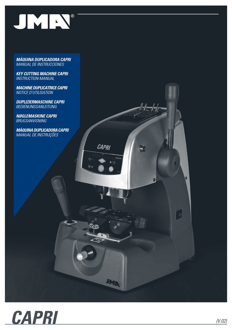
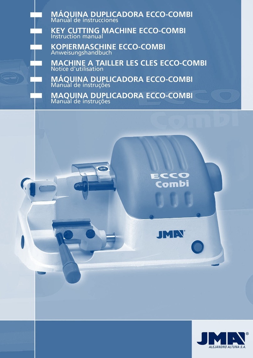
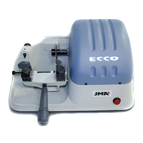
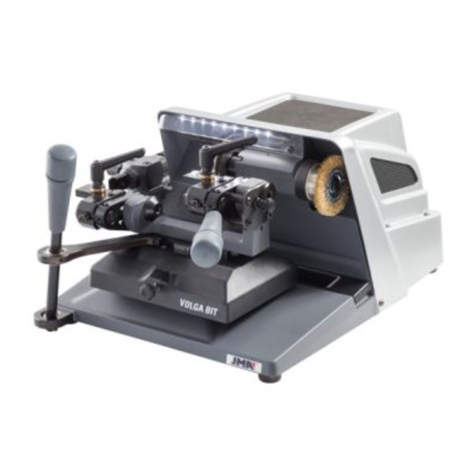
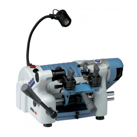
JMA CAPRI User manual

CAPRI
MÁQUINA DUPLICADORA CAPRI
MANUAL DE INSTRUCCIONES
KEY CUTTING MACHINE CAPRI
USER MANUAL
MACHINE DUPLICATRICE CAPRI
NOTICE D’UTILISATION
SCHLÜSSELKOPIERFRÄSE CAPRI
BEDIENUNGSANLEITUNG
NØGLEMASKINE CAPRI
BRUGSANVISNING
MÁQUINA DUPLICADORA CAPRI
MANUAL DE INSTRUÇÕES
(V.03)

ESPAÑOL
CAPRI
MANUAL DE INSTRUCCIONES
MÁQUINA DUPLICADORA

ESPAÑOL
1.- PRESENTACIÓN Y ASPECTOS GENERALES
1.1 GENERALIDADES
1.2 TRANSPORTE Y EMBALAJE
1.3 ETIQUETA IDENTIFICADORA
2.- MEDIDAS DE SEGURIDAD
2.1 NORMAS
2.2 DISPOSITIVOS DE SEGURIDAD
2.2.1 PROTECCIONES
2.2.2 EQUIPO DE PROTECCIÓN PERSONAL
2.2.3 SEÑALIZACIONES DE SEGURIDAD
2.2.4 INSTRUCCIONES GENERALES DE SEGURIDAD
2.3 RIESGOS RESIDUALES
3.- INSTALACIÓN Y PREPARACIÓN DE LA MÁQUINA
3.1 CONDICIONES AMBIENTALES DEL LOCAL.
3.2 CARACTERÍSTICAS DEL LUGAR DE INSTALACIÓN.
3.3 PREPARACIÓN DE LA MÁQUINA.
4.- CARACTERÍSTICAS DE LA MÁQUINA
4.1 FAMILIAS DE LLAVES
4.2 ACCESORIOS
4.3 ALMACÉN DE HERRAMIENTAS
4.4 CIRCUITO ELÉCTRICO
4.5 DATOS TÉCNICOS
4.6 ELEMENTOS PRINCIPALES DE LA MÁQUINA
4.7 COMPONENTES Y PARTES FUNCIONALES
4.7.1 CAMBIO DE FRESA Y DE PALPADOR
4.7.2 BLOQUEO DEL CARRO EN EL FIN DEL RECORRIDO DEL EJE “Y”
4.7.3 MORDAZA
5.- OPERATIVIDAD Y FUNCIONAMIENTO
5.1 PROCESO DE CIFRADO
5.2 CIFRADO DE LLAVES
5.2.1 LLAVES KA-2, KA-3 Y KA-4
5.2.2 LLAVE KE-1
5.2.3 LLAVE SEA-1
5.2.4 LLAVES OP-WH.P Y OP-WY.P
5.2.5 LLAVES ME-4.P, ME-6.P, ME-7P, ME-8P, ME-11P Y ME-12-P
5.2.6 LLAVES TUBULARES
5.2.7 LLAVES CISA
5.2.8 LLAVES HU-HAA
5.2.9 LLAVES REGATA DE PEQUEÑO ESPESOR
5.2.10 LLAVES TE-12P
5.2.11 LLAVES FIC-2 Y FIC-3
5.2.12 LLAVES WIN-1D, WIN-2D, WIN-3D Y WIN-4D
5.2.13 LLAVES JIS-4P
5.2.14 LLAVES FO-6P
5.2.15 LLAVES MCM-10
5.2.16 LLAVES TE-T60 Y TE-T80
6.- MANTENIMIENTO
6.1 SUSTITUCIÓN DE LAS GARRAS DE LA MORDAZA
6.2 REGLAJE DE LAS GARRAS
6.2.1 REGLAJE NORMAL
6.2.2 REGLAJE DE PRECISIÓN
6.3 SUSTITUCIÓN DE LOS FUSIBLES
6.4 TENSADO Y SUSTITUCIÓN DE LA CORREA
6.5 SUSTITUCIÓN DEL MOTOR
6.6 SUSTITUCIÓN DEL DISPLAY-TECLADO
6.7 SUSTITUCIÓN DE LA TARJETA ELECTRÓNICA DE CONTROL
6.8 SUSTITUCIÓN DE LA TARJETA DE POTENCIA Y DEL DISYUNTOR
7.- ELIMINACIÓN DE RESIDUOS
7.1 VIRUTA
7.2 EMBALAJE
7.3 MÁQUINA
8.- EXPLOSIONADO

ESPAÑOL
1.- PRESENTACIÓN Y ASPECTOS GENERALES
Este manual ha sido redactado por el constructor y constituye parte integrante del equi-
pamiento base de la máquina.
El manual ofrece una serie de informaciones que el operador debe obligatoriamente
conocer y que le permite utilizar la máquina en condiciones de seguridad
SIMBOLOGIA GRAFICA EN EL MANUAL DE USO
Señala las operaciones peligrosas para las personas y/o para el buen
funcionamiento de la máquina.
Es obligatorio leer el manual de uso
ES OBLIGATORIO respetar las normas de seguridad indicadas en el
manual, en particular, a la hora de utilizar y en operaciones de man-
tenimiento de la máquina.
ES OBLIGATORIO leer atentamente este manual ANTES de utilizar
la máquina.
Guardar este manual en un lugar protegido toda la vida de la máquina y siempre tiene
que estar a disposición del operario.
1.1 GENERALIDADES
La máquina duplicadora Capri ha sido diseñada teniendo en cuenta las Normativas
Europeas (CE).
En la fase de proyecto, se han tenido en cuenta soluciones que eliminan riesgos para
el operario a la hora de utilizar la máquina: transporte, reglajes, uso y mantenimiento.
Para garantizar un óptimo duplicado de la llave es necesario cumplir las siguientes
indicaciones:
• Respetar los procedimientos de este manual.
• Utilizar siempre Repuestos Originales JMA.
• Utilizar llaves en bruto JMA.
• Mandar a revisar periódicamente la máquina a un Centro de atención JMA autoriza-
do (Lista al final del manual).
USO NO PREVISTO
La máquina se ha de instalar y usar siguiendo las especificaciones definidas en el
manual. En el caso de un uso distinto, el fabricante declina toda responsabilidad por
cualquier daño a bienes o personas y se considera caducada cualquier tipo de garantía
sobre la máquina.
1.2 TRANSPORTE Y EMBALAJE
La máquina se presenta en una caja de cartón robusta protegida con espuma de emba-
laje de las siguientes dimensiones:
Ancho = 520 mm; Alto = 650 mm; Profundidad = 570 mm
Peso máquina más embalaje = 30 Kg.
Cuando desembale la máquina, inspecciónela cuidadosamente por si hubiese sufrido
algún daño en el transporte.
Si encuentra alguna anomalía, avise inmediatamente al transportista y no haga nada
con la máquina hasta que el agente del transportista haya realizado la inspección co-
rrespondiente.
Para desplazar la máquina de un lugar a otro, coger la máquina por los
asideros situados en su base, y no por otras partes.
Para asegurar la integridad de la máquina, siempre tiene que ser
transportada en su embalaje original.
1.3 ETIQUETA IDENTIFICADORA
La máquina duplicadora Capri está
provista de una etiqueta identificadora,
con especificación del número de serie
o matrícula de máquina, nombre y
dirección del fabricante, marca CE y año
de fabricación.
2.- MEDIDAS DE SEGURIDAD
2.1 NORMAS
La máquina duplicadora Capri y sus dispositivos de seguridad cumplen con la Directiva
sobre máquinas 2006/42 CE.
En el presente manual se citan todas las normas de seguridad que el usuario debe
respetar durante la instalación y el funcionamiento de la máquina. El incumplimiento de
estas instrucciones puede comprometer las condiciones de seguridad previstas durante
las fases de diseño y ensayos.
Cuando se emplean para el uso previsto, todas las máquinas con la marca CE cumplen
con la directiva de la UE sobre máquinas 2006/42 CE.
El usuario de la máquina debe conocer y respetar obligatoriamente las
instrucciones indicadas en el presente manual.
2.2 DISPOSITIVOS DE SEGURIDAD
La máquina duplicadora Capri está equipada con protecciones y dispositivos de seguri-
dad que delimitan el campo de acción del usuario, para garantizar su seguridad.
2.2.1 Protecciones
• Conexión de puesta a Tierra.
• DISYUNTOR. Se trata de un dispositivo que corta el paso de corriente eléctrica si
ocurre la siguiente situación: En caso de un corte repentino en el suministro eléctrico,
que provoque la parada del giro de la fresa, si el suministro eléctrico se restablece
inesperadamente, el disyuntor evita que la fresa se vuelva a poner repentinamente en
movimiento, evitando de este modo el riesgo que ello podría suponer para la integridad
del usuario. Bajo esta situación, es necesario apagar y volver a encender manualmente
la máquina, actuando sobre el interruptor de puesta en marcha.
• Protector contra la proyección de virutas. Lo que no exime de la obligatoriedad de
utilizar gafas de protección.
• Cerramiento de la zona inferior, para evitar el contacto con los componentes eléctri-
cos del interior de la máquina.
2.2.2 Equipo de protección personal
Durante el funcionamiento y mantenimiento de la máquina Capri, los usuarios deben
llevar el siguiente equipo de protección personal:
• VESTIMENTA: Los encargados del mantenimiento y los operadores de las máquinas
duplicadoras de llaves deben llevar ropa de protección que cumpla con los requisitos
básicos de seguridad actualmente en vigor. En caso de suelos resbaladizos, los usuarios
deben llevar calzado de seguridad con suela antideslizante.
• GAFAS DE SEGURIDAD: Durante las fases de duplicado, el operador debe llevar
puestas las gafas de protección.
2.2.3 Señalizaciones de seguridad
La máquina duplicadora Capri lleva las siguientes señalizaciones de seguridad:
Obligatorio el uso de gafas de protección
Leer el manual de instrucciones antes de usar la máquina
¡ATENCIÓN! Operación peligrosa
¡ATENCIÓN! Herramienta en movimiento de rotación
¡ATENCIÓN! Presencia de voltaje

ESPAÑOL
Conexión a Tierra
2.2.4 Instrucciones generales de seguridad
No desenchufar nunca la toma de Tierra, y asegúrese de que está siempre
conectada correctamente.
• Desconectar siempre el suministro eléctrico, antes de realizar cualquier operación de
mantenimiento o limpieza.
• Desconectar siempre el suministro eléctrico, cuando no se vaya a usar la máquina.
• Controlar periódicamente el estado de los cables. Si están desgastados, sustituirlos
inmediatamente.
• No mojar las conexiones eléctricas con agua u otros líquidos.
• No tirar nunca violentamente del cable de alimentación eléctrica.
• Controlar que el cable de alimentación eléctrica no se ponga en contacto con aceites,
objetos cortantes o calor.
• Durante las fases de duplicado, mantener siempre las manos sobre las palancas de
traslación del carro.
• Trabajar siempre con las manos secas y limpias de grasa o aceite.
• No usar la máquina en lugares peligrosos, húmedos o mojados.
• Todas las personas y especialmente los niños, deben guardar una distancia de segu-
ridad evitando el contacto con la máquina y con los cables eléctricos.
2.3 RIESGOS RESIDUALES
La máquina duplicadora Capri se ha diseñado con el máximo cuidado para que sea
segura durante las operaciones de transporte, ajuste, duplicado y mantenimiento. Sin
embargo, no se pueden eliminar todos los riesgos, ya sea por razones tecnológicas o
por cuestiones relacionadas con la utilización (operaciones excesivamente complica-
das). Por lo tanto, al utilizar la máquina se deben tener en cuenta los siguientes riesgos
residuales, así como los relacionados con su uso:
RIESGOS RELATIVOS AL LUGAR DE INSTALACIÓN
El lugar donde se instala la máquina puede presentar riesgos que podrían influir en el
correcto funcionamiento de la máquina (Temperatura, humedad, lluvia, ………)
RIESGO ELÉCTRICO
Dado que la máquina está equipada con dispositivos eléctricos, en caso
de avería puede haber riesgo de electrocución. La línea de alimentación
eléctrica debe estar equipada con los dispositivos de control y protección
adecuados (interruptor magneto-térmico e interruptor diferencial).
RIESGO MECÁNICO
La máquina está equipada con herramientas (fresa y palpador) necesarias para la ope-
ración de duplicado de llaves, por lo que el operario debe tener cuidado para evitar
cortarse las manos cuando duplica llaves o sustituye las herramientas.
El operario debe evitar collares, pulseras, anillos y/o ropa que puedan quedar atrapados
en la máquina o puedan enredarse en las partes móviles.
Se recomienda el uso de gorros para contener el pelo, especialmente en los casos de
operarios con pelo largo.
3- INSTALACION Y PREPARACION DE LA
MÁQUINA
La instalación de la máquina no presenta ninguna dificultad, es preferible que no inten-
te instalar, ajustar o manipular la misma sin leer previamente este manual. La máquina
sale de nuestra fábrica lista para el uso y solo necesita operaciones de calibrado para
los útiles que se van a utilizar.
3.1 CONDICIONES AMBIENTALES DEL LOCAL
• La máquina tiene que ser utilizada en lugares con temperatura ambiente 0º a 40º C,
con una humedad relativa inferior a 50 – 60% y un buen alumbrado de manera que se
pueda utilizar y realizar el mantenimiento correctamente.
• Se prohíbe la utilización de la máquina en atmosfera explosiva y en presen-
cia de líquidos inflamables o gases.
3.2 CARACTERISTICAS DEL LUGAR DE INSTALACION
• Coloque la maquina sobre una superficie horizontal de trabajo, firme y adecuada al
peso (25Kg)
• La altura de la mesa de trabajo tiene que estar adaptado a la altura del trabajador.
La altura tiene que coincidir con la pelvis del operador.
• Le recomendamos dejar 30 cm alrededor de la máquina para el normal uso y man-
tenimiento.
• La tensión de la máquina tiene que ser la misma del local y el local tiene
que tener conexión a tierra e interruptor diferencial.
3.3 PREPARACION DE LA MAQUINA
Una vez que la maquina se ha colocado en el puesto de trabajo, las piezas que vienen
embaladas aparte deberán ser montadas por el cliente de tal manera:
• Para montar la Palanca de accionamiento del cabezal, actuar de la siguiente manera:
- Soltar y extraer la brida que sujeta el mecanismo interno de accionamien-
to del cabezal.
- Introducir la Palanca en su correspondiente orificio.
- Empujar sobre la Palanca de arriba hacia abajo.
- Girar la Palanca en sentido horario, para atornillarla al sistema de blo-
queo de altura.
• Para ubicar el Almacén de herramientas tenemos dos opciones:
- Colocarlo en la parte superior de la máquina.
- Colocarlo sobre la mesa, al lado de la máquina.
4.-CARACTERÍSTICAS DE LA MÁQUINA
La máquina CAPRI es una duplicadora de gran robustez y precisión, que se caracteriza
por las múltiples posibilidades de sujeción que permite su mordaza, sin necesidad de
utilizar postizos ni adaptadores.
Incorpora un novedoso sistema de control de fuerza, que hace aumentar la precisión
del duplicado.
4.1 FAMILIAS DE LLAVES
La máquina CAPRI duplica entre otras, los siguientes tipos de llaves:
- Llaves de puntos
- Llaves de regata
- Llaves tubulares
- Llaves CISA
- Llaves HU-HAA
- Llaves JIS-4.P
- Llaves FO-6.P
4.2 ACCESORIOS
La máquina se suministra con una serie de accesorios para su uso y mantenimiento.
Todos estos accesorios pueden alojarse en el almacén de herramientas del que dispone
la máquina.
- 2 fusibles (alojados en la parte inferior del almacén de herramientas)
- Llaves allen de 5, de 3 y de 2.5
- 1 Llave allen especial de brazo corto de 1,5.
- 2 chapas de tope punta
- 2 ejes para el reglaje de las garras.
- 2 Adaptador para la llave tubular CHI-1T
- Fresas: F-1 y F-13
- Palpadores: T-1 y T-13.
4.3 ALMACÉN DE HERRAMIENTAS
La máquina dispone de un almacén de herramientas, que va montado en la parte supe-
rior de la máquina. Ofrece la posibilidad de extraerlo y apoyarlo directamente sobre una
mesa (de esta manera se obtiene un espacio extra en la parte superior de la máquina,
aprovechable para depositar llaves, accesorios, etc…).
4.4 CIRCUITO ELÉCTRICO
Los componentes principales del circuito eléctrico y electrónico son los siguientes:
1. Toma de corriente.
2. Placa de conexiones.
3. Interruptor de 3 posiciones.
4. Transformador.
5. Motor.
6. Display-teclado.
7. Tarjeta de control.

ESPAÑOL
- Activar el muelleo del palpador, para el cifrado de llaves de puntos
- Desactivar el muelleo del palpador, para el cifrado de llaves de regata.
17. Palanca apoyo tubular: Abatiendo 90º esta palanca, sirve de apoyo a la mano que
acciona la “palanca de traslación del carro”, durante el cifrado de llaves tubulares.
18. Almacén de herramientas: Accesorio que permite el almacenamiento de forma or-
denada, de las diferentes parejas de Fresas y Palpadores.
19. Protector de virutas: Evita la proyección de parte de la viruta generada durante el
duplicado, hacia el usuario de la máquina.
20. Guarda motor: Protege el sistema de transmisión de movimiento desde el motor
hasta el cabezal de giro de la Fresa.
21. Iluminación: Ilumina la zona de trabajo mediante tecnología Led.
22. Selector de velocidad: Para seleccionar la velocidad de giro de la Fresa.
- Velocidad 1 (baja), para Fresas de HSS.
- Velocidad 2 (alta). para Fresas de METAL DURO.
23. Enchufe: Para la toma de corriente eléctrica
El enchufe lleva un fusible de 6A/220V que protege ante un eventual fallo
que se pueda registrar en el circuito eléctrico.
24. Interruptor general: para poner en marcha o apagar la máquina
4.7 COMPONENTES Y PARTES FUNCIONALES
4.7.1 CAMBIO DE FRESA Y DE PALPADOR
Para soltar la fresa, hay que accionar el pulsador de bloqueo de la fresa al mismo
tiempo que con la mano hacemos girar el portaherramientas.
Después de extraer la fresa a reemplazar, introducir la nueva fresa y amarrarla en el
portaherramientas, asegurándonos de que su extremo hace tope en el interior del por-
taherramientas.
El palpador se reemplaza de la misma manera que la fresa. La única diferencia a tener
en cuenta es que el giro del palpador siempre se encuentra bloqueado internamente.
4.7.2 BLOQUEO DEL CARRO EN EL FIN DEL RECORRIDO DEL EJE “Y”
Con el objetivo de que el carro no se desplace en la dirección “Y”, durante el tiempo
que el duplicador está amarrando las llaves en la mordaza, se ha dotado al carro de un
bloqueo momentáneo en esta dirección.
Para accionar este bloqueo, basta con desplazar el carro hasta su tope de recorrido en
la dirección hacia el duplicador.
Para desactivar este bloqueo, basta con desplazar el carro hacia delante, haciendo un
poco de fuerza.
4.7.3 MORDAZA
Las prestaciones de la mordaza de la duplicadora CAPRI son superiores a las de una
máquina normal del mercado, al disponer de dos caras de amarre independientes. Ade-
más, las mordazas se pueden bloquear en cualquier posición de giro entre 45º 0º -45º.
5.- OPERATIVIDAD Y FUNCIONAMIENTO
5.1 PROCESO DE CIFRADO
• Encienda la máquina accionando el interruptor general situado en la parte trasera
derecha de la máquina.
• Para mejorar la visibilidad de la zona de trabajo, active la iluminación accionando el
interruptor situado en el display-teclado.
• Con ayuda de la tabla que se incluye en el presente manual, seleccionar la fresa y el
palpador necesarios para cifrar la llave.
• Cambiar la fresa y el palpador.
• Bloquear momentáneamente el carro en el fin de recorrido del eje “Y”.
• Amarrar la llave original en la parte izquierda de la mordaza, y la llave a cifrar en la
parte derecha. A la hora de amarrar las llaves, hay que tener en cuenta los siguientes
detalles:
- TOPE DE LA LLAVE. Puede tratarse de una llave de “tope-cuello” (Fig. 4.A),o de “to-
pe-punta” (Fig. 4.B).
- ADAPTADOR. En algún modelo de llave muy concreto, puede ser necesaria la utiliza-
ción de un adaptador.
- INCLINACIÓN. Algunas llaves tienen los puntos inclinados, por lo que será necesario
girar la mordaza.
• Hacer la regulación vertical del palpador.
• Activar los sistemas que simplifican el trabajo de duplicado:
- PALPADOR: Activar o desactivar el muelleo del palpador, en función del tipo de llave
a cifrar.
- CARRO: En función del modelo de llave, puede ser interesante activar el muelleo del
carro, o el bloqueo del carro en la dirección “X”.
- APOYO: en función del modelo de llave, puede ser interesante utilizar la palanca de
apoyo para llaves tubulares.
• Poner en marcha el giro de la fresa, eligiendo previamente una de las dos velocida-
des disponibles.
• Proceder al cifrado de la llave. Si la llave es de puntos, utilizar la ayuda del sistema
de “control de fuerza de duplicado”.
8. Fresa.
9. Palpador.
10. Mordaza.
11. Diodos LED de Iluminación.
12. Sensor de fuerza.
Ver Figura 2
4.5 DATOS TÉCNICOS
Motor: Monofásico 400 W. ,230 V - 50 Hz (Opcional: Monofásico 400W, 110V – 60Hz)
Fresa: HSS (Opcional: Metal duro)
Velocidad fresa: 6.000 y 11.000 r.p.m.
Mordazas: De dos caras de amarre y basculantes 0 / 45 º
Desplazamiento: En tres ejes con guías de rodillos de precisión.
Cursos útiles: Eje X = 71 mm; eje Y = 62 mm; eje Z = 40 mm
Iluminación: Diodos Led
Dimensiones: Ancho = 430 mm, Profundidad = 385 mm y Alto = 485 mm
Peso: 25 Kg
4.6 ELEMENTOS PRINCIPALES DE LA MÁQUINA
A continuación se describen los principales elementos de los que consta la máquina:
Ver figuras 3A y 3B
1. Display-teclado: Con las siguientes funcionalidades:
- Interruptor de iluminación: Activa y desactiva la iluminación de la zona de trabajo.
- Interruptor general del Display-teclado: Activa y desactiva las funcionalidades
del display-teclado.
- Indicador led luminoso:
Si se encuentra en color rojo, indica que la máquina está en marcha. Pero
las funcionalidades del display-teclado están desactivadas.
Si se encuentra en color verde, además de estar la máquina en marcha,
también están activadas las funcionalidades del display-teclado.
- Indicador de muelleo del palpador: Si está iluminado indica que el sistema de
muelleo del palpador está activado. Si está apagado, el sistema está desactivado.
- Interruptor MODE: Activa o desactiva el sistema luminoso de regulación de altura
de la Fresa y Palpador.
- Barra de leds: Indicador luminoso de la fuerza vertical ejercida por las herramien-
tas durante el cifrado de llaves de puntos. NOTA: Cuando se alcanza la fuerza ideal, la
máquina emite un sonido.
- Flechas: Indican el sentido hacia el que hay que girar el “Regulador altura Fre-
sa-Palpador” para efectuar el reglaje. La altura Fresa-Palpador está ajustada cuando se
iluminan al mismo tiempo las dos luces azules situadas junto a sus correspondientes
flechas.
2. Carro porta-mordazas: para el desplazamiento de la mordaza en las direcciones X e
Y mediante guías de precisión.
3. Palanca de traslación del carro: para desplazar el carro de tal manera que los diferen-
tes puntos de la llave se coloquen frente a la fresa.
4. Cabezal: para el desplazamiento vertical de la fresa y palpador (dirección Z).
5. Palanca de traslación del cabezal: para desplazar el cabezal hacia abajo durante la
fase de duplicado.
- Girándola en sentido horario, también sirve para bloquear el cabezal a la altura
deseada (necesario para duplicar llaves de regata).
Durante el duplicado es OBLIGATORIO tener las manos ocupando la palan-
ca de traslación del carro (3) y la palanca de translación del cabezal (5).
6. Pomo muelleo carro: para activar y desactivar el sistema de muelleo del carro en la
dirección X. Muy útil para el cifrado de llaves de regata.
7. Pomo bloqueo carro: para bloquear el carro en la dirección X. Muy útil en el cifrado
de llaves de puntos, para el cifrado de una hilera de puntos.
- Para activar este bloqueo, también debe estar activado el “Pomo de muelleo
carro”.
8. Mordaza:
- Giratorias.
- Con 2 lados de amarre.
- Con garras reemplazables.
9. Maneta mordaza: Para la apertura y cierre de las garras.
10. Maneta bloqueo giro mordaza: para bloquear el giro de la mordaza en el ángulo
requerido.
11. Porta-herramientas: Facilita el amarre de las herramientas (Fresa y Palpador) de una
manera rápida, cómoda y precisa.
12. Fresa: Fabricada en acero de alta velocidad HSS. Están disponibles fresas con di-
ferentes geometrías en función de la geometría de los puntos o ranuras de la llave a
duplicar.
13. Pulsador bloqueo fresa: para bloquear manualmente el giro de la fresa en el mo-
mento del intercambio de fresa.
14. Palpador: Específico para leer el cifrado de la llave. El palpador a utilizar debe ser la
pareja de la Fresa requerida para cada duplicado concreto.
15. Regulador altura Fresa-Palpador: para desplazar verticalmente la posición del Pal-
pador en el momento de realizar la regulación de altura entre Fresa y Palpador.
16. Maneta muelleo palpador: para activar y desactivar el sistema de muelleo del Pal-
pador.

ESPAÑOL
5.2 CIFRADO DE LLAVES
5.2.1 LLAVES KA-2, KA-3 Y KA-4.
• Dependiendo del modelo de llave a duplicar, se utiliza una pareja fresa-palpador
diferente. Mirar en la tabla.
• El amarre de la llave en la mordaza se realiza haciendo “tope cuello”.
• Dependiendo del modelo de llave a duplicar, es necesario girar las mordazas según
el ángulo requerido. Mirar en la tabla.
• Es preciso activar el muelleo del palpador.
• Para aumentar la precisión del cifrado, utilizar el sistema de “Control de fuerza de
duplicado”.
• NOTA: Los puntos tallados de la llave KA-3 deben ir siempre en la parte más baja de
la mordaza.
• NOTA: Los puntos tallados de la llave KA-2 deben ir siempre en la parte más alta de
la mordaza.
Ver Fig. 5
5.2.2 LLAVE KE-1.
• Utilizar la fresa-palpador: F-1 / P-1.
• El amarre de la llave en la mordaza se realiza haciendo “tope cuello”, pero introdu-
ciendo la llave por la parte de atrás.
• Es necesario posicionar las mordazas con un ángulo de inclinación de 5º.
• Es preciso activar el muelleo del palpador.
• Para aumentar la precisión del cifrado, utilizar el sistema de “Control de fuerza de
duplicado”.
• NOTA: Los puntos tallados de la llave KE-1 deben ir siempre en la parte más alta de
la mordaza.
• NOTA: Para el duplicado de los puntos laterales, hay que utilizar el adaptador corres-
pondiente.
Ver Fig. 6
5.2.3 LLAVE SEA-1.
• Utilizar la fresa-palpador: F-3 / P-3.
• El amarre de la llave en la mordaza se realiza haciendo “tope cuello”.
• Es preciso bloquear el palpador (desactivar el muelleo).
• NOTA: Después de realizar la regulación vertical del palpador, hay que bajar muy
ligeramente el palpador, girando para ello la rueda de regulación 5 puntos hacia la
derecha. Después, hay que introducir el palpador en el canal del paletón y bloquear
el cabezal de la máquina. Después hay que subir ligeramente el palpador, para que
éste no arrastre la llave.
• NOTA: Entrar por el centro del canal sin tocar los laterales, y en la segunda pasada
entrar por el lateral derecho y salir por el lateral izquierdo, sin hacer nada de presión
(únicamente apoyando ligeramente el palpador).
• NOTA: Para el duplicado de los puntos laterales utilizar la fresa-palpador F-1 / P-1.
Hacer “tope cuello”. Activar el muelleo del palpador, y utilizar el sistema de “Control
de fuerza de duplicado”.
Ver Fig. 7
5.2.4 LLAVES OP-WH.P Y OP-WY.P
• Utilizar la fresa-palpador: F-11 / P-11.
• El amarre de la llave en la mordaza se realiza haciendo “tope punta”.
• Es preciso bloquear el palpador (desactivar el muelleo).
• NOTA: Después de realizar la regulación vertical del palpador, hay que bajar muy
ligeramente el palpador, girando para ello la rueda de regulación 5 puntos hacia la
derecha. Después, hay que introducir el palpador en el canal del paletón y bloquear
el cabezal de la máquina. Después hay que subir ligeramente el palpador, para que
éste no arrastre la llave.
• NOTA: Es recomendable utilizar el sistema de muelleo del carro.
• NOTA: Se recomienda realizar una pasada de desbaste y luego otra pasada de aca-
bado siguiendo todo el perfil del dibujo de la llave. Se mecanizará en sentido des-
cendente (desde la punta de la llave hacia la cabeza).
Ver Fig. 8
5.2.5 LLAVES ME-4.P, ME-6.P, ME-7.P, ME-8.P, ME-11.P Y ME-12.P
• Utilizar la fresa-palpador: F-11 / P-11.
• El amarre de la llave en la mordaza, se realiza utilizando el adaptador AD-MM.
- Posicionar el adaptador sobre la mordaza, haciendo “tope punta”.
- Introducir la llave en el adaptador.
- Al mismo tiempo que amarramos el adaptador en la mordaza, la llave queda amarrada
en el adaptador.
• Es preciso bloquear el palpador (desactivar el muelleo).
• NOTA: Después de realizar la regulación vertical del palpador, hay que bajar muy
ligeramente el palpador, girando para ello la rueda de regulación 5 puntos hacia la
derecha. Después, hay que introducir el palpador en el canal del paletón y bloquear
el cabezal de la máquina. Después hay que subir ligeramente el palpador, para que
éste no arrastre la llave.
• NOTA: Es recomendable utilizar el sistema de muelleo del carro.
Ver Fig. 9
5.2.6 LLAVES TUBULARES
• Utilizar la fresa-palpador: F-8 / P-8.
• Amarrar la llave en la “V” de la mordaza. Para ello, utilizar el nuevo adaptador para
llaves tubulares.
• Es preciso activar el muelleo del palpador.
• La operación de tallado resultará más cómoda si apoyamos la mano que acciona la
palanca de accionamiento del carro, sobre la palanca de apoyo para llaves tubulares.
Ver fig. 10
5.2.7 LLAVES CISA
• Utilizar la fresa-palpador: F-1 / P-1.
• El amarre de la llave en la mordaza se realiza haciendo “tope cuello”.
• Es preciso activar el muelleo del palpador.
• Para aumentar la precisión del cifrado, utilizar el sistema de “Control de fuerza de
duplicado”.
Ver Fig. 11
5.2.8 LLAVES HU-HAA
• Utilizar la fresa-palpador: F-11 / P-11.
• El amarre de la llave en la mordaza se realiza haciendo “tope cuello”.
• Es preciso bloquear el palpador (desactivar el muelleo).
• NOTA: Después de realizar la regulación vertical del palpador, hay que bajar muy
ligeramente el palpador, girando para ello la rueda de regulación 5 puntos hacia la
derecha. Después, hay que introducir el palpador en el canal del paletón y bloquear
el cabezal de la máquina. Después hay que subir ligeramente el palpador, para que
éste no arrastre la llave.
• NOTA: Entrar por el centro del canal sin tocar los laterales, y en la segunda pasada
entrar por el lateral derecho y salir por el lateral izquierdo, sin hacer nada de presión
(únicamente apoyando ligeramente el palpador).
Ver Fig. 12
5.2.9 LLAVES REGATA DE PEQUEÑO ESPESOR
• Altura de la zona de amarre= 1.40
• Anchura mínima de llave= 7,00
• El amarre es por la parte trasera..
Ver Fig. 13
5.2.10 LLAVES TE-12P
• Utilizar la fresa-palpador: F-5 / P-5.
• El amarre de la llave en la mordaza se realiza haciendo “tope cuello”, pero introdu-
ciendo la llave por la parte de atrás.
• Para aumentar la precisión del cifrado, utilizar el sistema de “Control de fuerza de
duplicado”.
• NOTA: Las garras llevan integrados unos pequeños vaciados, para librar los pitones
que lleva la llave en la punta.
Ver Fig. 14
5.2.11 LLAVES FIC-2 Y FIC-3
• Utilizar la fresa-palpador: F-11 / P-11.
• El amarre de la llave en la mordaza se realiza utilizando el adaptador AD-2H.
-Posicionar el adaptador sobre la mordaza, haciendo tope hacia delante.
-Introducir la llave en el adaptador, haciendo tope hacia delante.
• Es preciso bloquear el palpador (desactivar el muelleo).
• Bloquear el cabezal de la máquina a una altura tal, que la fresa pase sobre la morda-
za pero sin rozarla.
• Proceder al tallado de los dos lados superiores.
• Girar las llaves teniendo cuidado de quitar las rebabas para asegurar el correcto
posicionamiento y amarre de la llave, y proceder al tallado de los otros dos lados
de la llave.
Ver Fig. 15
5.2.12 LLAVES WIN-1D, WIN-2D, WIN-3D Y WIN-4D.
• Utilizar la fresa-palpador: F-15 / P-15.
• El amarre de la llave en la mordaza se realiza utilizando la plantilla P-WIN, y hacien-
do “tope punta”.
• La llave original debe quedar amarada con el dentado hacia arriba (tal y como indica
el dibujo).
• Es preciso bloquear el palpador (desactivar el muelleo).
• Introducir el palpador exactamente en uno de los puntos, y bloquear el cabezal de la

ESPAÑOL
máquina a esa altura.
• Proceder al tallado.
Ver Fig. 16
5.2.13 LLAVE JIS-4.P
• Utilizar la fresa-palpador: F-11 / P-11.
• El amarre de la llave en la mordaza, se realiza utilizando el adaptador AD-MJ.
- Posicionar el adaptador sobre la mordaza, haciendo “tope punta”.
- Introducir la llave en el adaptador, haciendo “tope cuello” contra la placa que gira. En
esta posición, amarrar la llave en su adaptador.
• Es preciso bloquear el palpador (desactivar el muelleo).
Ver Fig. 17
5.2.14 LLAVE FO-6.P
• Utilizar la fresa-palpador F-22 / P-22.
• El amarre de la llave en la mordaza, se realiza utilizando su adaptador correspon-
diente.
- Posicionar y amarrar los adaptadores sobre la mordaza.
- Al colocar la llave, hay que tener cuidado de que quede bien plana, para que los dos
tallados queden por igual.
• Es preciso bloquear el palpador (desactivar el muelleo).
• Introducir el palpador dentro del canal de una letra. Bloquear el cabezal de la máqui-
na, y subir el palpador ligeramente para que no talone contra el adaptador.
• Proceder al tallado.
Ver Fig. 18
Lectura del código de la llave original
• La llave original tiene 6 posiciones de duplicado, que están definidas mediante las
letras: A, B, C, D, E y F, según se muestra en la siguiente figura
• En cada una de las posiciones que posee la llave, existen 4 distintas combinaciones
posibles (definidas mediante números), que ahora señalamos y vamos a numerar:
1 2 3 4
• La “altura” n.º1, nos indica que no se debe duplicar. La posición n.º2 nos señala
que hay un pequeño rebaje en la llave y que cuando es algo mayor corresponde a la
altura n.º3. La altura n.º4 es el mayor de los rebajes de la llave.
• Entonces cogeríamos la llave y marcaríamos las combinaciones de cada una de las 6
posiciones, tal y como señalamos a continuación, a modo de ejemplo:
POSICIÓN A B C D E F
COMBINACIÓN 3 4 1 2 4 2
NOTA: La serie de números de la combinación es el código de la llave.
5.2.15 LLAVE MCM-10.
• Colocación especial en la mordaza. Ver figura.
Ver fig.19
5.2.16 LLAVE TE-T60 Y TE-T80
• Colocación especial en la mordaza. La llave TE-T60 se amarra como se indica en el
dibujo.
• La llave TE-T80 tiene la particularidad que para mecanizar el lado izquierdo se amarra
como la TE-T60 y para mecanizar el lado derecho hay que amarrar la llave por la
parte posterior de la mordaza (como en el caso de la MCM-10).
Ver Fig. 20
6.- MANTENIMIENTO
La máquina duplicadora Capri no precisa de un plan de mantenimiento particular. En
todo caso es oportuno que se controlen y eventualmente se sustituyan algunas piezas a
medida que se desgasten. Nos referimos en particular a la fresa, el cepillo, el palpador
y la correa.
Las operaciones de mantenimiento deben ser efectuadas por personal cualificado y do-
tado de los medios de protección necesarios para trabajar en condiciones de seguridad.
Para realizar cualquier operación de mantenimiento, es necesario seguir escrupulosa-
mente las indicaciones del presente manual, y cumplir con las siguientes indicaciones
de carácter general:
Antes de comenzar con cualquier operación de mantenimiento, se debe
apagar la máquina y desconectarla de la red eléctrica. El operador debe asegurarse de
que nadie pueda acceder a la máquina.
No efectuar ninguna operación de mantenimiento mientras la máquina
esté en funcionamiento.
Se deben utilizar siempre piezas de recambio originales. Se garantiza la
marca “CE” sólo si se utilizan repuestos originales suministrados por el constructor.
Tras el reemplazo de un componente, asegurarse de que los tornillos co-
rrespondientes quedan amarrados correctamente.
¡NO USAR EN ABSOLUTO AIRE COMPRIMIDO! Para mantener las mor-
dazas y el carro limpios de virutas metálicas, se recomienda utilizar el pincel que se
suministra junto a la máquina.
Para proteger las partes metálicas de la máquina frente a la oxidación, se
recomienda utilizar aceite protector del tipo WD40 o similar, aplicándolo sobre morda-
zas.
6.1 SUSTITUCIÓN DE LAS GARRAS DE LA MORDAZA
La mordaza de la máquina CAPRI dispone de tres parejas de garras (garra fija izquierda,
garra fija derecha y garra móvil). En el caso de que alguna de ellas resultase dañada,
pueden reemplazarse por garras nuevas, de manera independiente.
Para reemplazar la “garra fija izquierda” (A) o la “garra fija derecha” (B), basta con des-
enroscar los dos tornillos de amarre que la sujetan, y extraerlas tirando de ellas hacia
arriba. Para montar las nuevas garras, actuar de manera inversa.
Para reemplazar la “garra móvil” (C), hay que seguir los siguientes pasos:
Apagar la máquina mediante el interruptor general y desconectar el cable
de alimentación.
1) Extraer con ayuda de un cutter o similar, la tapa negra de plástico que tiene la ma-
neta de la mordaza.
2) Mientras se bloquea la contratuerca con una llave fija de 14, introducir una llave
allen de 5 por el orificio que ha quedado descubierto en la maneta de la mordaza, y
desenroscarla.
3) Posicionar la mordaza con un ángulo de inclinación de 45º, y girando manualmente el
husillo, extraerlo por uno de los laterales. Una vez extraído el husillo, la garra móvil
queda liberada y ya la podemos retirar.
4) Para montar la nueva garra móvil, actuar de manera inversa.
NOTA IMPORTANTE: Cuando se reemplaza la garra fija izquierda o la garra fija de-
recha, siempre hay que hacer el reglaje de la pareja de garras que se ha reemplazado.
En cambio, si se reemplaza la garra móvil, no es necesario realizar ninguna operación
de reglaje en las garras.
Ver Fig. 21
6.2 REGLAJE DE LAS GARRAS
Siempre que se reemplaza la garra fija izquierda o la garra fija derecha, hay que hacer
el reglaje de la pareja de garras que se ha reemplazado. En cambio, el reemplazo de la
garra móvil no conlleva ninguna operación de reglaje en las garras.
Existen dos maneras diferentes de realizar el reglaje de las garras:
Reglaje NORMAL
Reglaje de PRECISION
6.2.1 REGLAJE NORMAL
Se trata de un reglaje rápido y sencillo, con el que conseguimos un reglaje aceptable
como para poder duplicar llaves con cierta precisión.
Para realizar este reglaje, seguir los siguientes pasos:
Apagar la máquina mediante el interruptor general y desconectar el cable
de alimentación.
1) Amarrar los dos ejes de reglaje en sus correspondientes portaherramientas, de forma
que hagan tope en el interior del portaherramientas y que la parte cónica de los ejes de
reglaje queden en el exterior.

ESPAÑOL
2) La garra fija izquierda del lado derecho de la mordaza, y la garra fija derecha del lado
izquierdo de la mordaza, no tienen posibilidad de regulación, ya que van posicionadas
mediante pasadores. Por lo tanto, hay que montarlas guiándolas por sus pasadores, y
a continuación amarrarlas mediante sus correspondientes tornillos.
3) Por lo tanto, sabiendo que en cada pareja de garras hay una que tiene su posición fija,
tenemos que reglar la otra garra respecto de la que tiene su posición fija.
4) Colocar los tornillos de la garra a reglar, pero sin apretarlos. De forma que la garra
se pueda mover con la mano, pero que a su vez no tenga posibilidad de levantarse
respecto de la superficie donde va apoyada
5) Proceder a reglar la garra:
5.1) Introducir el eje de reglaje del palpador, en el orificio Nº1 de la garra.
5.2) Hacer coincidir el eje de reglaje de la fresa, en el orificio Nº1 de la otra garra.
5.3) Elevar el cabezal y realizar la misma operación, pero en el orificio Nº2 de las garras.
5.4) Volver a repetir el punto anterior tantas veces como sea necesario, hasta que los
ejes de reglaje entren suavemente y sin forzar, tanto en el orificio Nº1 como en el
Nº2.
A
B
1
2
5.5) Con los dos ejes de reglaje introducidos en los orificios Nº1, bloquear el cabezal, y
amarrar ligeramente el tornillo B.
5.6) Con los dos ejes de reglaje introducidos en los orificios Nº2, bloquear el cabezal, y
amarrar ligeramente el tornillo A.
5.7) Repetir la operación del punto anterior, pero amarrando definitivamente los tor-
nillos A y B.
5.8) Una vez terminado el reglaje, con ayuda de la llave allen de 1,5 especial de brazo
corto, apretar los dos tornillos prisioneros situados entre la maneta de la mordaza y la
garra que hemos reglado. De esta manera, aseguramos una mayor consistencia en la
fijación de la garra que hemos reglado.
6.2.2 REGLAJE DE PRECISIÓN
Se trata de un reglaje que requiere de cierta destreza, y con el que conseguimos un
reglaje muy preciso de las garras reemplazadas.
Para realizar este reglaje, seguir los siguientes pasos:
Apagar la máquina mediante el interruptor general y desconectar el cable
de alimentación.
1) La garra fija izquierda del lado derecho de la mordaza, y la garra fija derecha del lado
izquierdo de la mordaza, no tienen posibilidad de regulación, ya que van posicionadas
mediante pasadores. Por lo tanto, hay que montarlas guiándolas por sus pasadores, y
a continuación amarrarlas mediante sus correspondientes tornillos.
2) Por lo tanto, sabiendo que en cada pareja de garras hay una que tiene su posición fija,
tenemos que reglar la otra garra respecto de la que tiene su posición fija.
3) Colocar los tornillos de la garra a reglar, pero sin apretarlos. De forma que la garra
se pueda mover con la mano, pero que a su vez no tenga posibilidad de levantarse
respecto de la superficie donde va apoyada.
4) Con ayuda de la llave allen de 1,5 especial de brazo corto, desenroscar alrededor
de 1 vuelta los dos tornillos prisioneros de regulación de la garra (son los dos tornillos
prisioneros situados entre la maneta de la mordaza y la garra que vamos a reglar).
5) A continuación, montar cualquier pareja de Fresa-Palpador en sus correspondientes
portaherramientas, pero al revés (con las puntas de corte hacia el interior del porta-
herramientas. Bajar el cabezal de la máquina, y bloquearlo a una altura en la cuál las
herramientas puedan tocar los laterales de la garras.
6) Activar el sistema electrónico de regulación vertical del palpador.
7) Apoyar el extremo de la garra que está amarrada (la que tiene su posición fija), contra
el lateral de la herramienta. Manualmente, desplazar la garra a reglar en la dirección
de la maneta de la mordaza, y manteniendo la presión sobre la garra en esa dirección,
desplazarla frontalmente hasta que también toque lateralmente su correspondiente
herramienta. En esta posición, apretar ligeramente los tornillos de amarre de la garra.
Sabremos cuándo las herramientas están tocando sus correspondientes garras, porque
las luces del sistema electrónico de regulación vertical del palpador, se iluminarán.
8) A continuación, separar la garra móvil de la garra a reglar, girando para ello la ma-
neta de la mordaza.
9) Colocar la herramienta alineada con uno de los tornillos de amarre de la garra, y en
esta posición apoyar la herramienta contra la garra que está amarrada (la que tiene
su posición fija). En este momento, y manteniendo en todo momento una muy ligera
presión entre la herramienta y la garra que está amarrada (la que tiene su posición fija),
ir apretando muy despacio, el tornillo prisionero que está alineado con la herramienta
y con el tornillo de la garra. Llegará un momento en el que se encenderá la segunda luz
del sistema electrónico de regulación vertical del palpador. Cuando llegue ese momen-
to, dejar de apretar el tornillo prisionero.
10) Colocar la herramienta alineada con el otro tornillo de amarre de la garra, y volver
a realizar la misma operación.
11) Revisar de nuevo que las garras han quedado regladas en esas dos posiciones (fren-
te a los tornillos de amarre), y si fuese necesario, retocar ligeramente la posición de la
garra apretando muy ligeramente el correspondiente tornillo prisionero.

ESPAÑOL
12) Ya se ha realizado el reglaje, por lo que ahora hay que apretar con fuerza los dos
tornillos de amarre de la garra.
13) Por último, apretar un poco los dos prisioneros de regulación de la garra. De esta
manera, aseguramos una mayor consistencia en la fijación de la garra que hemos re-
glado.
6.3 SUSTITUCIÓN DE LOS FUSIBLES
En el caso de que la máquina no se ponga en marcha cuando se accionen los interrup-
tores de marcha, es necesario comprobar los fusibles. Esta operación se realiza de la
siguiente manera:
Apagar la máquina mediante el interruptor general y desconectar el cable
de alimentación.
1) Extraer el porta-fusible que se encuentra debajo del interruptor general.
2) Comprobar (usar un tester) si algún fusible está fundido, y en su caso, sustituirlo por
otro del mismo tipo y valor.
6.4 TENSADO Y SUSTITUCIÓN DE LA CORREA
Para revisar el tensado de la correa o para sustituir la misma, deben seguirse los si-
guientes pasos:
Apagar la máquina mediante el interruptor general, y desconectar el cable
de alimen tación.
1) Desatornillar los 4 tornillos (5) que amarran el “guarda del cabezal” y extraerlo. Los
tornillos se encuentran en el lateral derecho, en el lateral izquierdo, en la parte su-
perior, y en la parte trasera. Para poder extraer el “guarda del cabezal”, es necesario
introducir previamente y hasta su tope, el “pulsador de bloqueo de la fresa” (E).
2) Aflojar pero sin soltar, los 4 tornillos (6) que sujetan el motor.
3) Aflojar pero sin soltar, las 2 tuercas de contratuerca (7).
Tensado: Girando los dos tornillos de tensado (8), se produce el desplazamiento del
motor hacia la parte trasera de la máquina. Cuando se observe que la correa dispone
de la tensión requerida, volver a apretar las dos tuercas de contratuerca (7), y los
tornillos (6) que sujetan el motor.
Sustitución: Aflojar pero sin soltar, los 2 tornillos de tensado de la correa (8). Ex-
traer la correa estropeada y sustituirla por una nueva. Girando los dos tornillos de ten-
sado (8), se produce el desplazamiento del motor hacia la parte trasera de la máquina.
Cuando se observe que la correa dispone de la tensión requerida, volver a apretar las
dos tuercas de contratuerca (7), y los tornillos (6) que sujetan el motor.
4) Volver a colocar y amarrar el “guarda del cabezal”.
Ver Fig. 22
6.5 SUSTITUCIÓN DEL MOTOR
Esta operación se realiza de la siguiente manera:
Apagar la máquina mediante el interruptor general, y desconectar el cable
de alimentación.
1) Desatornillar los 4 tornillos (5) que amarran el “guarda del cabezal” y extraerlo. Los
tornillos se encuentran en el lateral derecho, en el lateral izquierdo, en la parte su-
perior, y en la parte trasera. Para poder extraer el “guarda del cabezal”, es necesario
introducir previamente y hasta su tope, el “pulsador de bloqueo de la fresa” (E).
2) Desatornillar los 6 tornillos (9) que amarran el “guarda del motor” (F) y extraerlo.
3) Extraer la correa (G).
4) Desconectar los cables de alimentación que llegan hasta el motor.
5) Desatornillar los 4 tornillos (6) que sujetan el motor.
6) Extraer el motor.
7) Accediendo a la parte inferior del motor con un destornillador plano, bloquear el eje
del motor y manualmente girar la polea (H) hasta extraerla (la rosca es a izquierdas).
8) Desenroscar los 4 tornillos (10) que amarran la chapa-soporte del motor y extraerla.
9) Para montar el nuevo motor, efectuar las mismas operaciones pero de manera in-
versa.
Ver Fig. 23
6.6 SUSTITUCIÓN DEL DISPLAY-TECLADO
Esta operación se realiza de la siguiente manera:
Apagar la máquina mediante el interruptor general, y desconectar el cable
de alimentación.
1) Desatornillar los 4 tornillos (5) que amarran el “guarda del cabezal” y extraerlo. Los
tornillos se encuentran en el lateral derecho, en el lateral izquierdo, en la parte su-
perior, y en la parte trasera. Para poder extraer el “guarda del cabezal”, es necesario
introducir previamente y hasta su tope, el “pulsador de bloqueo de la fresa” (E).
2) Desconectar el cable plano, que conecta el display-teclado (K) con la tarjeta electró-
nica de control.
3) Despegar el viejo display-teclado (K) del “Guarda del cabezal”, y extraerlo.
4) Para montar el nuevo display-teclado, efectuar las mismas operaciones pero de ma-
nera inversa.
Ver Fig. 24
6.7 SUSTITUCIÓN DE LA TARJETA ELECTRÓNICA DE
CONTROL
Esta operación se realiza de la siguiente manera:
Apagar la máquina mediante el interruptor general, y desconectar el cable
de alimentación.
1) Desatornillar los 4 tornillos (5) que amarran el “guarda del cabezal” y extraerlo. Los
tornillos se encuentran en el lateral derecho, en el lateral izquierdo, en la parte su-
perior, y en la parte trasera. Para poder extraer el “guarda del cabezal”, es necesario
introducir previamente y hasta su tope, el “pulsador de bloqueo de la fresa” (E).
2) Desconectar el conector principal de la tarjeta electrónica de control (L)
3) Desconectar el cable plano, que conecta el display-teclado con la tarjeta electrónica
de control (L).
4) Desatornillar los 3 tornillos (11) que sujetan la tarjeta electrónica de control (L) al
“guarda del cabezal”, y extraerla.
5) Para montar la nueva tarjeta electrónica de control, efectuar las mismas operaciones
pero de manera inversa.
Ver Fig. 25
6.8 SUSTITUCIÓN DE LA TARJETA DE POTENCIA Y DEL
DISYUNTOR
Esta operación se realiza de la siguiente manera:
Apagar la máquina mediante el interruptor general, y desconectar el cable
de alimentación.
1) Desatornillar las 4 patas (P) de la máquina, y extraerlas.
2) Desatornillar los 5 tornillos (12) que amarran la “Chapa de protección inferior”, y
retirarla.
3) Desconectar todos los cables de la tarjeta que queramos reemplazar, anotando pre-
viamente la posición de cada cable.
4) Para liberar la tarjeta de potencia (M) o el disyuntor (N), basta con presionar sobre
las lengüetas de cada uno de los 4 pivotes que la sustentan, y tirar de la tarjeta hacia
arriba.
5) Para montar la nueva tarjeta de potencia o el nuevo disyuntor, efectuar las mismas
operaciones pero de manera inversa.
Ver Fig. 26
7.- ELIMINACIÓN DE RESIDUOS
La eliminación de residuos debe gestionarse de acuerdo con la legislación vigente en
el país del usuario.
El instalador de la máquina es quien tiene la responsabilidad de gestionar
correctamente los residuos.
7.1 VIRUTA
Las virutas producidas durante el duplicado de llaves están clasificadas como residuos
especiales y se asimilan a los residuos sólidos urbanos (RSU) como por ejemplo pudiera
ser un estropajo metálico.
Los casos relativos a residuos contaminados o que contienen sustancias tóxicas y no-
civas, se consideran residuos tóxicos o nocivos y se eliminan de acuerdo con la legisla-
ción vigente en el país del usuario.
7.2 EMBALAJE
El embalaje en el que se suministra la máquina es de cartón, por lo que podría reciclarse
como caja de embalaje. Como desecho, se equipara a los desechos sólidos urbanos y
por lo tanto deberá desecharse en los contenedores especiales para cartón.
Los cascos que protegen la máquina en el interior de la caja de cartón, son de material
polimérico equiparable a los desechos sólidos urbanos y por lo tanto, no se pueden
eliminar más que en las instalaciones apropiadas de eliminación de desechos.
7.3 MÁQUINA
Cuando sea necesaria su eliminación, la máquina se considera perteneciente a la cate-
goría de los RAEE (Residuos de Aparatos Eléctricos y Electrónicos).

ESPAÑOL
En “Cumplimiento de la Directiva 2012/19/UE sobre los residuos de aparatos eléctricos
y electrónicos (RAEE)”
Quien se deshaga de la máquina de forma ilegal o como residuo doméstico, estará
sujeto a las sanciones previstas por la legislación nacional vigente.
Según lo previsto por las normas nacionales vigentes, la máquina no puede ser elimi-
nada como residuo urbano. Por lo tanto, al final de su ciclo de vida, después de haber
realizado las operaciones necesarias para una correcta gestión, el aparato tiene que
ser entregado a una de las instalaciones de recogida selectiva para los residuos de
aparatos eléctricos y electrónicos procedentes de hogares particulares.
Las instalaciones de recogida del municipio donde se vive, deben garantizar la fun-
cionalidad, la accesibilidad y la adecuación de los sistemas de recogida selectiva, de
manera que los propietarios de la máquina y los distribuidores puedan entregar gratui-
tamente en la instalación de recogida, los residuos producidos en su territorio.
8.- EXPLOSIONADO
Ver Figura 23

ENGLISH
Capri
INSTRUCTION MANUAL
KEY CUTTING MACHINE

ENGLISH
1.- INTRODUCTION AND OVERVIEW
1.1 OVERVIEW
1.2 TRANSPORT AND PACKAGING
1.3 ID LABEL
2.- SAFETY MEASURES
2.1 REGULATIONS
2.2 SAFETY DEVICES
2.2.1 USER PROTECTION
2.2.2 PERSONAL PROTECTION EQUIPMENT
2.2.3 SAFETY SIGNS AND SYMBOLS
2.2.4 GENERAL SAFETY INSTRUCTIONS
2.3 RESIDUAL RISKS
3.- INSTALLATION AND PREPARATION OF THE MACHINE
3.1 ENVIRONMENTAL CONDITIONS IN THE WORKSHOP
3.2 CHARACTERISTICS OF THE LOCATION FOR
INSTALLATION
3.3 PREPARATION OF THE MACHINE
4.- MACHINE CHARACTERISTICS
4.1 KEY TYPES
4.2 ACCESSORIES
4.3 TOOLBOX
4.4 ELECTRIC CIRCUIT
4.5 TECHNICAL DATA
4.6 MAIN ELEMENTS OF THE MACHINE
4.7 COMPONENTS AND FUNCTIONAL PARTS
4.7.1 CHANGING THE CUTTER AND TRACER POINT
4.7.2 BLOCKING THE SLIDE AT THE END OF THE “Y” AXIS TRAVEL
4.7.3 CLAMP
5.- OPERATION AND FUNCTIONS
5.1 KEY CUTTING PROCESS
5.2 KEY CUTTING
5.2.1 KA-2, KA-3 AND KA-4 KEYS
5.2.2 KEY KE-1
5.2.3 KEY SEA-1
5.2.4 KEYS OP-WH.P Y OP-WY.P
5.2.5 KEYS ME-4.P, ME-6.P, ME-7P, ME-8P, ME-11P Y ME-12-P
5.2.6 TUBULAR KEYS
5.2.7 CISA KEYS
5.2.8 HU-HAA KEY
5.2.9 ARROW CHANNEL KEYS
5.2.10 KEYS TE-12P
5.2.11 KEYS FIC-2 Y FIC-3
5.2.12 KEYS WIN-1D, WIN-2D, WIN-3D Y WIN-4D
5.2.13 KEYS JIS-4P
5.2.14 KEYS FO-6P
5.2.15 KEYS MCM-10
5.2.16 KEYS TE-T60 Y TE-T80
6.- MAINTENANCE
6.1 REPLACING THE CLAMP JAWS
6.2 ADJUSTING THE JAWS
6.2.1 NORMAL ADJUSTMENT
6.2.2 PRECISION ADJUSTMENT
6.3 REPLACING THE FUSES
6.4 TIGHTENING AND REPLACING THE BELT
6.5 REPLACING THE MOTOR
6.6 REPLACING THE KEYBOARD-DISPLAY
6.7 REPLACING THE ELECTRONIC CONTROL CARD
6.8 REPLACING THE POWER CARD AND CIRCUIT BREAKER
7.- WASTE DISPOSAL
7.1 SWARF
7.2 PACKAGING
7.3 MACHINE
8.- EXPLODED VIEW

ENGLISH
1.- INTRODUCTION AND OVERVIEW
This manual has been written by the manufacturer and forms an integral part of the basic
equipment supplied with the machine.
This manual provides information that the operator should be aware of and that will enable
safe use of the machine.
SYMBOLS USED IN THE MANUAL
Indicates a dangerous operation for people and/or proper operation of the
machine.
Reading the user manual is obligatory
The safety rules expressed in this manual MUST be followed, espe-
cially when using or maintaining the machine.
This manual MUST be read carefully before using the machine.
Keep this manual in a safe place for as long as you have the machine and ensure
that it is always available to the operator.
1.1 OVERVIEW
The Capri duplicator machine has been designed to meet European Regulations (EC).
Solutions have been applied to the design that seek to eliminate risks for the operator when
using the machine: transport, adjustment, use and maintenance.
The following instructions should be followed to ensure proper key duplication:
• Follow the procedures defined in this manual.
• Always use Original JMA Parts.
• Use JMA key blanks.
• Send the machine to an authorised JMA Customer Service Centre for regular servicing (a
list can be found at the end of this manual).
IMPROPER USE
The machine must be installed and used according to the instructions contained in this ma-
nual. The manufacturer accepts no liability for any material damage or personal injury if the
machine is used improperly and any improper use will void all guarantees to which the ma-
chine may be subject.
1.2 TRANSPORT AND PACKAGING
The machine is housed in a robust cardboard box protected in packing foam. The parcel has
the following dimensions:
Width = 520 mm, Height = 650 mm, Depth = 575 mm
Machine weight including packaging = 30 kg.
Inspect the machine carefully on opening the parcel to ensure that no damage occurred during
transport.
If there is an anomaly, please contact the transport company immediately and do not use the
machine until they have carried out their inspection.
To move the machine from one place to another, only lift the machine by the
base and not by any other parts.
The machine must always be transported in its original packaging to ensure its
physical integrity.
1.3 ID LABEL
The Capri duplication machine has an ID label
with the serial or machine registration number
as well as the manufacturer’s name and address,
EC label and year of manufacture.
2.-SAFETY MEASURES
2.1 REGULATIONS
The Capri duplicator machine and its safety devices are compliant with Directive 2006/42
EC on Machinery.
This manual cites all the safety regulations that the user must respect when installing and
operating the machine. Failure to follow these instructions may compromise the safety condi-
tions provided for during design and testing.
When used for the purpose for which they have been designed, all machines bearing the CE
mark are compliant with EU Directive 2006/42 EC on Machinery.
The machine operator must know and follow the instructions provided in
this manual.
2.2 SAFETY DEVICES
The Capri duplicator machine is fitted with safety and other protective devices that define the
user operation area in order to guarantee their safety.
2.2.1 User protection
• Earthing connection
• CIRCUIT BREAKER. This device stops the flow of electricity in the event of the following: If
the electricity supply suddenly fails and prevents the cutter from rotating, the circuit breaker
prevents the cutter from suddenly moving again if electrical power unexpectedly returns and
thereby prevents any risk this may pose to user integrity. If this happens, the machine must be
manually switched off and on again by using the power switch.
• Anti-swarf screen. The operator must still wear safety goggles even though this device is
present.
• Enclosure for the lower section, to prevent contact with the electrical components inside
the machine.
2.2.2 Personal protection equipment
When operating or maintaining the Capri machine, users must wear the following personal
protection equipment:
• CLOTHING: Those responsible for maintaining and operating key duplicator machines
should wear protective clothing that meets all the basic safety requirements currently in
effect. On wet floors, users should wear safety shoes with a non-slip sole.
• SAFETY GOGGLES: The operator should wear safety goggles over the eyes during the du-
plication stages of operation.
2.2.3 Safety signs and symbols
The Capri duplicator machine uses the following safety signs and symbols:
Safety goggles must be worn
Read the instruction manual before using the machine
WARNING! Hazardous operation
WARNING! Rotating tool
WARNING! Electrical voltage
Earthing connection
2.2.4 General safety instructions
Never disconnect the Earthing connection and make sure it is always connected
correctly.
• Always disconnect the power supply before carrying out any maintenance or cleaning.
• Always disconnect the power supply when the machine is not in use.
• Check the condition of cables regularly. If they are worn or damaged, replace them imme-
diately.
• Keep all electrical connections safe from water and other liquids.
• Do not pull violently on the electrical power cord.
• Ensure that the electrical power cord does not come into contact with oils, sharp objects
or heat.
• During the duplication stages, always keep your hands on the carriage assembly motion

ENGLISH
controls.
• Always work with dry hands free of grease and oil.
• Do not use the machine in hazardous, damp or wet locations.
• Everyone, and especially children, should keep a safe distance to prevent contact with the
machine and the electrical cables.
2.3 RESIDUAL RISKS
The Capri duplicator machine has been designed with the utmost care to ensure it is safe
during transport, adjustment, duplication and maintenance. Nonetheless, it is impossible
to eliminate all risks, whether for technological reasons or for issues related to use of the
machine (excessively complex operations). Therefore, the following residual risks should be
taken into consideration when using the machine, as well as the risks associated with its use:
RISKS RELATED TO THE INSTALLATION LOCATION
The location where the machine is installed may present risks that could impact correct ope-
ration of the machine (temperature, humidity, rain, etc.)
ELECTRICAL RISK
Given that the machine is fitted with electrical devices, a risk of electrocution exists if a fault
were to occur. The electrical power cord should be fitted with suitable control and protection
devices (thermal magnetic circuit breaker and differential circuit breaker).
MECHANICAL RISK
The machine is fitted with tools (cutter and tracer) that are necessary for key duplication. The
operator should therefore be careful in order to prevent cutting their hands when duplicating
keys or replacing the tools.
The operator should avoid wearing necklaces, bracelets, rings and/or clothing that could be-
come trapped in the machine or get caught up in the moving parts.
We recommend wearing a cap to cover and contain your hair, especially for those operators
with long hair.
3.- INSTALLATION AND PREPARATION OF THE
MACHINE
Installation of this machine presents no difficulty whatsoever, but you should not attempt to
install, adjust or operate the machine without reading this user manual first. The machine
leaves our factory ready for use and only needs to be calibrated for the tools that are going
to be used.
3.1 ENVIRONMENTAL CONDITIONS IN THE WORKSHOP
• The machine should be used in places with an ambient temperature of between 0º and
40º C, a relative humidity of less than 50-60% and good lighting so that it can be used and
maintained correctly.
• Use of the machine in explosive atmospheres or in the presence of flammable
liquids or gases is strictly prohibited.
3.2 CHARACTERISTICS OF THE LOCATION FOR
INSTALLATION
• Place the machine on a solid horizontal work surface capable of properly supporting its
weight (25 kg)
• The height of the work bench should be adapted to the height of the operator. The machine
should be at the same height as the pelvis of the operator.
• We recommend leaving 30 cm of free space around the machine for normal use and main-
tenance.
• The voltage connected to the machine should be the same as that connected to
the workshop and the workshop should have an Earthing connection and differential circuit
breaker.
3.3 PREPARATION OF THE MACHINE
After positioning the machine on the work bench, the parts that come packaged separately
will need to be assembled by the customer as follows:
•Follow the steps below to assemble the head operation lever:
- Release and remove the flange securing the internal operation mechanism from the
head.
- Insert the lever in its corresponding orifice.
- Push downwards on the lever.
- Rotate the lever clockwise to screw it into the height locking system.
- There are two ways to position the tool holder:
- On top of the machine.
- On the bench, next to the machine.
• Connect the power cord to the electrical power supply.
4.-MACHINE CHARACTERISTICS
The CAPRI machine is a highly robust and precision key cutting machine, which stands
out for having a clamp that enables many different types of keys to be clamped, without
the need for any adaptors.
It incorporates a novel force control system, which increases cutting precision.
4.1 KEY TYPES
The CAPRI machine cuts the following types of keys, among others:
- Dimple keys
- Wave keys
- Tubular keys
- CISA keys
- HU-HAA keys
- JIS-4.P keys
- FO-6.P keys
4.2 ACCESSORIES
The machine is supplied with a number of accessories for its use and maintenance. All
these accessories can be housed in the machine’s tool store.
- 2 fuses (housed in the bottom of the tool store)
- Set of Allen keys (5, 3 and 2.5)
- 1 special 1.5 short-arm Allen key
- 2 tip-stop strips
- 2 jaw adjustment rods.
- 2 adaptors for CHI-1T tubular key
- Cutters: F-1 and F-13
- Tracer points: T-1 and T-13.
4.3 TOOLBOX
The machine has a tool store, which is fitted to the top of the machine. It can be remo-
ved and laid directly on a table (in this way providing extra space on top of the machine,
which can be used for keeping keys, accessories, etc…).
4.4 ELECTRIC CIRCUIT
The main components of the electric and electronic circuits are as follows:
Socket.
Connection plate.
3-position switch.
Transformer.
Motor.
Keypad-display.
Control card.
Cutter.
Tracer point.
Clamp.
Lighting LED.
Force sensor.
See Figure 2
4.5 TECHNICAL DATA
Motor: Single phase 400 W. ,230 V - 50 Hz (Optional: Single phase 400W, 110V – 60Hz)
Cutter: HSS (Optional: Hard metal)
Cutter speed: 6,000 and 11,000 r.p.m.
Clamps: Two clamping faces and 0 / 45 º tilting
Displacement: On three axes with precision roller guides.
Effective stroke: X axis = 71 mm; Y axis = 62 mm; Z axis = 40 mm
Lighting: LED
Dimensions: Width = 430 mm, Depth = 385 mm and Height = 485 mm
Weight: 25 Kg
4.6 MAIN ELEMENTS OF THE MACHINE
The main parts of the machine are described below:
See Figures 3A and 3B
1. Display-keypad: With the following features:
- Light switch: Turns the light on and off in the work area.

ENGLISH
- Display-keypad master switch: Turns the display-keypad features on and off.
- LED indicator:
This is red when the machine is running. But the display-keypad features
are off.
It will be green when the machine is running and the display-keypad featu-
res are also on.
- Tracer spring action indicator: If this is lit, it means the tracer spring action
system is enabled. If it is off, then the system is disabled.
- MODE switch: This turns the illuminated cutter and tracer height adjustment
system on and off.
- LED strip: Lights indicating the vertical force applied by the tools when cutting
dimple keys. NOTE: When optimal force is achieved, the machine emits a sound.
- Arrows: These indicate the direction in which the cutter-tracer height regulator
should be turned for adjustment. The cutter-tracer height is properly adjusted when the
two blue lights next to their corresponding arrows light up at the same time.
2. Clamp carriage assembly: for moving the clamp on the X and Y axes via precision
guide rails.
3. Carriage assembly control lever: for moving the carriage assembly so that various
points of the key are positioned next to the cutter.
4. Head: for moving the cutter and tracer vertically (Z axis).
5. Head control lever: for moving the head downwards when cutting a key.
- By turning it clockwise, it can also be used to lock the head at the desired height
(necessary for cutting sidewinder keys).
The operator MUST hold the carriage assembly control lever (3) and the
head control lever (5) when cutting keys.
6. Carriage spring action handle: for enabling and disabling the carriage assembly
spring action system on the X axis. Very useful when cutting sidewinder keys.
7. Carriage lock handle: for locking the carriage on the X axis. Very useful when cut-
ting a row of dimples on the same X axis on dimple keys.
- To enable this lock, the carriage assembly spring action handle also needs to be
enabled.
8. Clamp:
- Rotating.
- With two usable sides.
- With interchangeable grips.
9. Clamp handle: For opening and closing the clamps.
10. Clamp rotation locking handle: for locking clamp rotation at the required angle.
11. Tool chuck: This makes inserting tools (cutter and tracer) quick, convenient and
precise.
12. Cutter: Made from high-speed steel (HSS). Cutters are available in different sha-
pes and sizes based on the geometry of the dimples or grooves on the key being copied.
13. Cutter lock button: for manually locking cutter rotation when switching cutters.
14. Tracer: specifically designed to read the key coding. The tracer to be used should
be the one corresponding to the cutter required for each specific copy.
15. Cutter-tracer height regulator: for moving the tracer position vertically to adjust the
height between cutter and tracer.
16. Tracer spring action handle: for enabling and disabling the tracer spring action
system.
- Enable the tracer spring action system when cutting dimple keys.
- Disable the tracer spring action system when cutting sidewinder keys.
17. Tubular support lever: Pulling this lever 90º provides support for the hand operating
the carriage assembly control lever when cutting tubular keys.
18. Tool holder: An accessory that lets you store various cutter and tracer sets in a tidy
fashion.
19. Swarf protective shield: This prevents the swarf created when cutting keys from
being ejected outwards from the machine towards the operator.
20. Motor housing: This protects the motion transmission system between the motor
and the rotating head of the cutter.
21. Lights: This illuminates the work area using LED technology.
22. Speed selector: For selecting the cutter rotation speed.
- Speed 1 (low) for HSS cutters.
- Speed 2 (high) for TOUGHENED METAL cutters.
23. Plug: For connection to a power supply
The plug is fitted with a 6A/220V fuse that protects against any potential
faults in the electrical circuit.
24. Master switch: for switching the machine on or off.
4.7 COMPONENTS AND FUNCTIONAL PARTS
4.7.1 CHANGING THE CUTTER AND TRACER POINT
To release the cutter, you have to press the cutter blocking button and at the same time
rotate the tool-holder by hand.
After removing the cutter to be replaced, insert the new cutter and secure it in the
tool-holder, making sure that its end butts up against the inside of the tool-holder.
The tracer point is replaced in the same way as the cutter. The only difference to bear in
mind is that the rotation of the tracer point is always blocked internally.
4.7.2 BLOCKING THE SLIDE AT THE END OF THE “Y” AXIS TRAVEL
In order to prevent the slide from moving in the “Y” direction, whilst the key cutting
machine is holding the keys in the clamp, the slide has been equipped with momentary
blocking in that direction.
To active this blocking, just move the slide as far as it will go in the direction towards
to the key cutting machine.
To deactivate the blocking, just move the slide forward, exercising a little force.
4.7.3 CLAMP
The features of the clamp on the CAPRI key cutting machine are superior to those of any
normal machine on the market, as it has two separate clamping faces. In addition, the
clamps can be blocked in any rotation position between 45º 0º -45º.
5.- OPERATION AND FUNCTIONS
5.1 KEY CUTTING PROCESS
• Switch on the machine using the main switch located on the back right-hand side
of the machine.
• To improve visibility in the work area, activate the lighting by turning on the switch
located on the keypad-display.
• With the help of the table provided in this manual, select the cutter and tracer
point necessary to cut the key.
• Change the cutter and tracer point.
• Momentarily block the slide at the end of the “Y” axis travel.
• Secure the original key in the left side of the clamp, and the key to be cut in the
right side. When securing the keys, bear in mind the following details:
- KEY STOP. It may be a key which is stopped from being inserted further by its
shoulders (Fig. 4.A), or a key stopped by its tip (Fig. 4.B).
- ADAPTOR. For some very specific types of key, it may be necessary to use an
adaptor.
- ANGLE CUT. Some keys have angle cut dimples, for which it is necessary to
rotate the clamp.
• Carry out the vertical adjustment of the tracer point.
• Activate the systems which simplify the cutting work:
TRACER POINT: Activate or deactivate the tracer point spring mechanism,
depending on the type of key being cut.
SLIDE: Based on the model of key, it may be a good idea to activate the slide
spring mechanism, or block the slide in the “X” direction.
SUPPORT: Depending on the type of key, it may be a good idea to use the support
lever for tubular keys.
• Start rotating the cutter, having first selected one of the two speeds available.
• Proceed to cut the key. If it is a dimple key, use the help of the cutting force
control system.
5.2 KEY CUTTING
5.2.1 KA-2, KA-3 AND KA-4 KEYS.
• Different pairs of cutters and tracer points are used depending on the key to be cut.
See table.
• The key is secured in the clamp when its shoulders stop it from being inserted any
further.
• Depending on the model of key to be cut, it is necessary to rotate the clamps based
on the angle required. See table.
• It is necessary to activate the tracer point spring mechanism.
• Use the cutting force control system to increase cutting precision.
• NOTE: The dimples cut on the KA-3 key must always be on the lowest part of the
clamp.
• NOTE: The dimples cut on the KA-2 key must always be on the highest part of the
clamp.
See Fig. 5
5.2.2 KE-1 KEY.
• Use cutter-tracer point pair: F-1 / P-1.
• The key is secured in the clamp when its shoulders stop it from being inserted any
further, but in this case it is inserted from the back.
• It is necessary to position the clamps at an angle of 5º.
• It is necessary to activate the tracer point spring mechanism.
• Use the cutting force control system to increase cutting precision.
• NOTE: The dimples cut on the KE-1 key must always be on the highest part of the
clamp.
• NOTE: You have to use the relevant adaptor to cut the lateral dimples.
See Fig. 6
5.2.3 SEA-1 KEY.
• Use cutter-tracer point pair: F-3 / P-3.
• The key is secured in the clamp when its shoulders stop it from being inserted any
further.
• It is necessary to block the tracer point (deactivate the spring mechanism).
• NOTE: After vertically adjusting the tracer point, you need to slightly lower the
tracer point, by turning the adjustment wheel 5 points to the right. Then you have to

ENGLISH
insert the tracer point in the channel of the bit and block the machine head. Next slightly
raise the tracer point so that it does not drag the key.
• NOTE: Enter through the middle of the channels without touching the sides, and on
the second pass enter from the right side and exit from the left, without exercising any
pressure (just gently supporting the tracer point).
• NOTE: To cut the lateral dimples, use the cutter-tracer point combination: F-1 /
P-1. Insert until shoulders stop the key from going in any further. Activate the tracer
point spring mechanism and use the cutting force control system.
See Fig. 7
5.2.4 OP-WH.P AND OP-WY.P KEYS
• Use cutter-tracer point pair: F-11 / P-11.
• The key is secured in the clamp when its tip stops it from being inserted any fur-
ther.
• It is necessary to block the tracer point (deactivate the spring mechanism).
• NOTE: After vertically adjusting the tracer point, you need to slightly lower the
tracer point, by turning the adjustment wheel 5 points to the right. Then you have to
insert the tracer point in the channel of the bit and block the machine head. Next slightly
raise the tracer point so that it does not drag the key.
• NOTE: We recommend using the slide spring mechanism system.
• NOTE: We recommend you do a roughing pass and then another finishing pass
following the whole profile of the pattern of the key. Machine in a downward direction
(from the tip of the key to the head).
See Fig. 8
5.2.5 ME-4.P, ME-6.P, ME-7.P, ME-8.P, ME-11.P AND ME-12.P
• Use cutter-tracer point pair: F-11 / P-11.
• Secure the key in the clamp using the AD-MM adaptor.
- Position the adaptor on the clamp, so that it is stopped by the tip.
- Insert the key into the adaptor.
- As you secure the adaptor in the clamp, the key is secured in the adaptor.
• It is necessary to block the tracer point (deactivate the spring mechanism).
• NOTE: After vertically adjusting the tracer point, you need to slightly lower the
tracer point, by turning the adjustment wheel 5 points to the right. Then you have to
insert the tracer point in the channel of the bit and block the machine head. Next slightly
raise the tracer point so that it does not drag the key.
• NOTE: We recommend using the slide spring mechanism system.
See Fig. 9
5.2.6 TUBULAR KEYS
• Use the tracer-point. F-8 / P-8.
• Fix the key into the “V” of the clamp, to do that, use the new adaptor for tubular keys.
• You have to activate the springing of the tracer.
• The cutting operation is more comfortable is we support the hand activating the
carriage activation level on the support level for tubular keys.
See Fig. 10
5.2.7 CISA KEYS
• Utilizar la fresa-palpador: F-1 / P-1.
• El amarre de la llave en la mordaza se realiza haciendo “tope cuello”.
• Es preciso activar el muelleo del palpador.
• Para aumentar la precisión del cifrado, utilizar el sistema de “Control de fuerza
de duplicado”.
See Fig. 11
5.2.8 HU-HAA KEY
• Use the tracer-point. F-11 / P-11.
• Fix the key into the clamp until the “neck stop”.
• The tracer must be blocked (deactivate the springing).
• NOTE: After vertically regulating the tracer, this should be slightly lowered by
turning the regulation wheel 5 points to the right. Then, the tracer has to be intro-
duced into the bit channel and the machine head blocked. Then the tracer should be
slightly raised so it does not pull the key.
• NOTE: Enter by the centre of the channel without touching the edges, and in the
second pass enter by the right side and come out by the left side, without applying
any pressure (only lightly supporting the tracer).
See Fig. 12
5.2.9 NARROW CHANNEL KEYS
• Height of the fixing area = 1.40
• Minimum height of the key = 7.00
• The fixing is done at the rear
See Fig. 13
5.2.10 TE-12P KEY
• Use the tracer-point. F-5 / P-5.
• Fix the key into the clamp until the “neck stop”, but introducing the key from the rear.
• You have to activate the springing of the tracer.
• The increase the coding precision, use the “Control of duplicating force” system.
• NOTE: The clamps have some small spaces, to free to allow the pins at the
points of the key.
See Fig. 14
5.2.11 FIC-2 AND FIC-3 KEYS
• Use the tracer-point. F-11 / P-11.
• The key is fixed into the clamp by using the AD-2H adaptor.
-Position the adaptor on the clamp, until it reaches the front limit.
-Introduce the key into the adaptor, until it reaches the front stop.
• The tracer must be blocked (deactivate the springing).
• Block the head of the machine at a height allowing the cutter to pass over the
clamp without touching it.
• Cut the two upper sides.
• Turn the keys taking, taking care to carefully remove the burs to assure the
correct positioning and fixing of the key, and cut the two other sides of the key.
See Fig. 15
5.2.12 WIN-1D, WIN-2D, WIN-3D AND WIN-4D KEYS.
• Use the tracer-point. F-15 / P-15.
• The key is fixed into the clamp using the P-WIN template and reaching the “point limit”.
• The original key should be fixed with the teeth upwards (as shown in the drawing).
• The tracer must be blocked (deactivate the springing).
• Introduce the tracer exactly on one of the points, and lock the head of the machine
at that height.
• Proceed with the cutting.
See Fig. 16
5.2.13 JIS-4.P KEY
• Use cutter-tracer point pair: F-11 / P-11.
• Secure the key in the clamp using the AD-MJ adaptor.
-Position the adaptor on the clamp, so that it is stopped by the tip.
-Insert the key into the adaptor, until its shoulders are stopped by the plate that
rotates. In this position, clamp the key in the adaptor.
• It is necessary to block the tracer point (deactivate the spring mechanism).
See Fig. 17
5.2.14 FO-6.P KEY
• Use cutter-tracer point pair: F-22 / P-22.
• Secure the key in the clamp, using the relevant adaptor.
- Position and secure the adaptors on the clamp.
- When positioning the key, make sure that it is really flat, so that the two cuts
are the same.
• It is necessary to block the tracer point (deactivate the spring mechanism).
• Insert the tracer point if the groove of a letter. Block the machine head and raise
the tracer point slightly so that it does not knock against the adaptor.
• Start cutting.
See Fig. 18
Reading the code on the original key
• The original key has 6 cutting positions, which are defined by the letters: A, B, C, D,
E and F, as shown in the figure below.
• In each of the key’s positions, there are 4 different possible combinations (defined by
numbers), which we are going to indicate and number:
1 2 3 4

ENGLISH
• Height no. 1, indicates that it should not be cut. Position no. 2 indicates there is a
small notch in the key and when it is slightly deeper this is position no. 3. Height no. 4
is the deepest notch in the key.
• You then take the key and mark the combinations of each of the 6 positions, as
shown below, by way of example:
POSITION A B C D E F
COMBINATION 3 4 1 2 4 2
NOTE: The series of combination numbers is the key code.
5.2.15 MCM-10 KEY.
• Special positioning in the clamp. See figure.
See Fig.19
5.2.16 TE-T60 AND TE-T80 KEYS
• Special positioning in the clamp. The TE-T60 is clamped as shown in the drawing.
• The TE-T80 key has the peculiarity that to machine the left side it is clamped like
the TE-T60 and to machine the right side the key has to be clamped by the back part of
the clamp (like with the MCM-10 key).
See Fig. 20
6.-MAINTENANCE
The Capri duplicator machine requires no particular maintenance plan. Nonetheless, certain
parts should be checked regularly and eventually replaced once they become worn. This par-
ticularly includes the cutter, the brush, the tracer and the belt.
Maintenance operations should be carried out by qualified professionals with the necessary
protective equipment for working safely.
The instructions provided in this manual should be followed carefully when performing any
maintenance tasks and the following instructions should be followed in general:
The machine should be switched off and disconnected from the power supply
before starting any maintenance operations. The operator should make sure that nobody can
access the machine.
Do not perform any maintenance operations while the machine is in operation.
Original spare parts should always be used. The “CE” mark is only guaranteed
when original spare parts supplied by the manufacturer are used.
After replacing a component, make sure that the corresponding screws are in
their correct position.
NEVER USE COMPRESSED AIR! We recommend using the small brush supplied
with the machine for keeping the clamps and carriage assembly free from metallic swarf.
We recommend using protective oil (WD40 or similar) to protect the metal parts
of the machine against oxidation, applying it to the clamps
6.1 REPLACING THE CLAMP JAWS
The CAPRI machine’s clamp has three pairs of jaws (left fixed jaw, right fixed jaw and
moving jaw). If any of them become damaged, you can replace them with new jaws,
separately.
To replace the left fixed jaw (A) or the right fixed jaw (B), you just have to undo the two
screws securing them, and remove them by pulling them upwards. Reverse the process
to fit the new jaws.
To replace the moving jaw (C), you need to follow the steps below:
Switch off the machine using the main switch and unplug it.
1) With the help of a cutter or something similar, remove the clamp knob’s black
plastic cover.
2) Whilst locking the locknut with a size 14 spanner, insert a no. 5 Allen key into the
hole revealed in the clamp knob, and unscrew it.
3) Tilt the clamp 45º, and manually turning the spindle, remove it from one of the
sides. Once the spindle has been removed, the moving jaw is released and you can
remove it.
4) To fit the new moving jaw, simply reverse the process.
IMPORTANT NOTE: When you replace the left fixed jaw or the right fixed jaw, you
always have to adjust the pair of jaws that has been replaced. On the other hand, if you
replace the moving jaw, it is not necessary to carry out any adjustment on the jaws.
See Fig. 21
6.2 ADJUSTING THE JAWS
Whenever you replace the left fixed jaw or the right fixed jaw, you have to adjust the
pair of jaws that has been replaced. On the other hand, the replacement of the moving
jaw does not require any adjustment to the jaws.
There are two different ways of adjusting the jaws:
NORMAL adjustment
PRECISION adjustment
6.2.1 NORMAL ADJUSTMENT
This is a quick, simple adjustment, which will give you an acceptable adjustment ena-
bling you to cut keys with a certain amount of precision.
To carry out this adjustment, follow these steps:
Switch off the machine using the main switch and unplug it.
1) Secure the two adjustment rods in their relevant tool-holders, inserting then as far
as they will go into the tool-holder, with the tapered part of the adjustment rods on the
outside.
2) The left fixed jaw on the right-hand side of the clamp and the right fixed jaw on the
left-hand side of the clamp cannot be adjusted, as they are held in position by means of
pins. So you have to fit them, by guiding them with their pins and then securing them
with their corresponding screws.
3) Therefore, knowing that in each pair of jaws there is one with a fixed position, you
have to adjust the other jaw in relation to the one with the fixed position.
4) Insert the screws for the jaw to be adjusted, but do not tighten them. So that the
jaw can be moved by hand, but cannot lift up from the surface it is resting on.
5) Adjust the jaw:
5.1) Insert the tracer point adjustment rod into hole no. 1 in the jaw.
5.2) Make the cutter adjustment rod coincide with hole no. 1 in the other jaw.
5.3) Raise the head and carry out the same operation, with hole no. 2 in the jaws.
5.4) Repeat this operation as many times as necessary until the adjustment rods
enter smoothly without the need for any force, in both hole no. 1 and hole
no. 2.

ENGLISH
A
B
1
2
5.5) With the two adjustment rods inserted in holes no. 1, block the head, and
slightly tighten screw B.
5.6) With the two adjustment rods inserted in holes no. 2, block the head and
slightly tighten screw A.
5.7) Repeat the above operation, but fully tightening screws A and B.
5.8) Once you have completed the adjustment process, with the help of the special
short-arm 1.5 Allen key, tighten the two setscrews located between the clamp
knob and the jaw you have adjusted. This will ensure that the jaw you have adjus-
ted is tightly secured.
6.2.2 PRECISION ADJUSTMENT
This adjustment requires a certain amount of skill, and ensures that the replaced jaws
are very precisely adjusted.
To carry out this adjustment, follow these steps:
Switch off the machine using the main switch and unplug it.
1) The left fixed jaw on the right-hand side of the clamp and the right fixed jaw on the
left-hand side of the clamp cannot be adjusted, as they are held in position by means of
pins. So you have to fit them, by guiding them with their pins and then securing them
with their corresponding screws.
2) Therefore, knowing that in each pair of jaws there is one with a fixed position, you
have to adjust the other jaw in relation to the one with the fixed position.
3) Insert the screws for the jaw to be adjusted, but do not tighten them. So that the
jaw can be moved by hand, but cannot lift up from the surface it is resting on.
4) With the help of the special short-arm 1.5 Allen key, unscrew the two jaw adjust-
ment setscrews about 1 turn (these are the two setscrews located between the clamp
knob and jaw you are going to adjust).
5) Then, insert any cutter-tracer point pair in their corresponding tool-holders, but
the wrong way around (with the cutting tips inside the tool-holder). Lower the machine
head, and block it at a height at which the tools can touch the sides of the jaws.
6) Activate the tracer point electronic vertical adjustment system.
7) Rest the end of the jaw that is clamped (the one with the fixed position) against
the side of the tool. Manually, move the jaw to be adjusted in the direction of the clamp
knob, and maintaining pressure on the jaw in that direction, move it forward until it also
touches the side of its corresponding tool. In this position, tighten the screws securing
the jaw a little. You will know when the tools are touching their corresponding jaws,
because the tracer point electronic vertical adjustment system’s lights will come on.
8) Then, separate the moving jaw from the jaw to be adjusted, turning the clamp knob
to do so.
9) Position the tool in alignment with one of the screws securing the jaw, and in
this position rest the tool against the jaw that is clamped (the one with the fixed po-
sition). Then, keeping at all times a slight pressure between the tool and the jaw that
is clamped (the one with the fixed position), very slowly tighten the setscrew aligned
with the tool and the jaw screw. The moment will come when the second light on the
tracer point electronic vertical adjustment system will come on. When this happens,
stop tightening the setscrew.
10) Position the tool in alignment with the other screw securing the jaw, and carry out
the same operation again.
11) Check again that the jaws are adjusted in those two positions (in front of the
clamping screws), and if necessary, slightly adjust the position of the jaw tightly very
slightly the corresponding setscrew.
12) You have now completed the adjustment. Now you have to fully tighten the two
screws securing the jaw.
13) Finally, tighten the two jaw adjustment setscrews a little. This will ensure that the
jaw you have adjusted is tightly secured.
6.3 REPLACING THE FUSES
If the machine does not start when you activate the on-off switches, you need to check
the fuses. You can do this in the following way:
Switch of the machine using the main switch and unplug it.
1) Remove the fuse-holder which is under the main switch.
2) Use a tester to check if a fuse has blown and, if so, replace it with one of the same
type and value.
6.4 TIGHTENING AND REPLACING THE BELT
To check the tightness of the belt or to replace it, follow these steps:
Switch off the machine using the main switch, and unplug it.
1) Undo the 4 screws (5) securing the head guard and remove it. The screws are on
the right side, the left side, on the top and at the back. To remove the head guard it is
necessary first of all to push the cutter locking button right in as far as it will go (E).
2) Loosen but do not undo the 4 screws (6) securing the motor.
3) Loosen but do not undo the 2 locknut nuts (7).
Tightening: When you turn the two tightening screws (8), the motor moves towards
the back of the machine. When you see that the belt is tight enough, tighten up the two
locknut nuts (7) again, and the screws (6) securing the motor.
Replacement: Loosen but do not undo the 2 screws tightening the belt (8). Remove the
damaged belt and replace it with a new one. When you turn the two tightening screws
(8), the motor moves towards the back of the machine. When you see that the belt is
tight enough, tighten up the two locknut nuts (7) again, and the screws (6) securing
the motor.
4) Put the head guard back and secure it in place.
See Fig. 22

ENGLISH
6.5 REPLACING THE MOTOR
You can carry out this operation in the following way:
Switch off the machine using the main switch and unplug it.
1) Undo the 4 screws (5) securing the head guard and remove it. The screws are on
the right side, the left side, on the top and at the back. To remove the head guard it is
necessary first of all to push the cutter locking button right in as far as it will go (E).
2) Undo the 6 screws (9) securing the motor guard (F) and remove it.
3) Remove the belt (G).
4) Disconnect the power cables going to the motor.
5) Undo the 4 screws (6) securing the motor.
6) Remove the motor.
7) Access the bottom of the motor with a flat screwdriver, block the motor shaft and
manually turn the pulley (H) until it comes out (it is left-threaded).
8) Undo the 4 screws (10) securing the motor support plate and remove it.
9) To fit the new motor, reverse the procedure above.
See Fig. 23
6.6 REPLACING THE KEYBOARD-DISPLAY
You can carry out this operation in the following way:
Switch off the machine using the main switch, and unplug it.
1) Undo the 4 screws (5) securing the head guard and remove it. The screws are on
the right side, the left side, on the top and at the back. To remove the head guard it is
necessary first of all to push the cutter locking button right in as far as it will go (E).
2) Disconnect the flat cable connecting the keypad-display (K) to the electronic con-
trol card.
3) Release the old keypad-display (K) from the head guard and remove it.
4) To fit the new keypad-display, reverse the procedure above.
See Fig. 24
6.7 REPLACING THE ELECTRONIC CONTROL CARD
You can carry out this operation in the following way:
Switch off the machine using the main switch and unplug it.
1) Undo the 4 screws (5) securing the head guard and remove it. The screws are on
the right side, the left side, on the top and at the back. To remove the head guard it is
necessary first of all to push the cutter locking button right in as far as it will go (E).
2) Disconnect the electronic control card’s main connector (L)
3) Disconnect the flat cable connecting the keypad-display (K) to the electronic con-
trol card
4) Undo the 3 screws (11) securing the electronic control card (L) to the head guard
and remove it.
5) To fit a new electronic control card, reverse the procedure above.
See Fig. 25
6.8 REPLACING THE POWER CARD AND CIRCUIT
BREAKER
You can carry out this operation in the following way:
Switch off the machine using the main switch and unplug it.
1) Unscrew the machine’s 4 feet (P) and remove them.
2) Undo the 5 screws (12) the lower protection plate and remove it.
3) Disconnect all the cables from the card you want to replace, noting down before-
hand the position of each cable.
4) To release the power card (M) or the circuit breaker (N), just press on the lugs on
each of the 4 pins holding it, and pull the card up.
5) To fit the new power card or circuit breaker, just reverse the procedure above.
See Fig. 26
7.- WASTE DISPOSAL
Waste disposal should be managed according to the legislation in force in the user’s country.
The installer of the machine is responsible for managing any waste correctly.
7.1 SWARF
The swarf produced during key duplication is classified as special waste and falls into the
same category of solid urban waste (SUW) as a metal scourer, for example.
Contaminated waste or waste containing toxic or harmful substances is considered as toxic
or harmful waste and must be disposed of according to the legislation in force in the user’s
country.
7.2 PACKAGING
The machine is supplied in cardboard packaging, which can be recycled with all other card-
board packing material. It is considered as solid urban waste and should therefore be dispo-
sed of in the special containers for cardboard.
The material used to protect the machine inside the cardboard box is polymeric and compara-
ble to solid urban waste. It must therefore be sent to the appropriate waste disposal facilities
for processing.
7.3 MACHINE
When needing to dispose of the machine, it falls into the WEEE category (Waste Electrical
and Electronic Devices).
In “Compliance with Directive 2012/19/EU on waste electrical and electronic equipment
(WEEE)”
Anyone found disposing of the machine illegally or as domestic waste will be subject to the
penalties provided for by current national legislation.
Pursuant to the provisions of current national regulations, the machine cannot be disposed
of as urban waste. Therefore, at the end of its life cycle and after performing the necessary
operations for correct management, the apparatus must be delivered to one of the selective
collection facilities for waste electrical and electronic equipment from private homes.
The collection facilities of the municipality where you live must guarantee the functionality,
accessibility and suitability of their selective collection systems so that the owners of the ma-
chine and the distributors may deliver any waste produced within its territory to the collection
facility for free.
8.- EXPLODED VIEW
See Figure 23
Other manuals for CAPRI
1
Table of contents
Languages:
Other JMA Cutter manuals
Popular Cutter manuals by other brands

Sunrise Electronic Technology
Sunrise Electronic Technology Skycut Series C with SignMaster manual

Mejix
Mejix CMER 200A manual

Mafell
Mafell NFU 32 Operating instructions and spare parts list

ProsKit
ProsKit FB-1601 user manual

Racing
Racing TCA-L25 Instruction guide

EINHELL Expert
EINHELL Expert TE-TC 620 U Original operating instructions