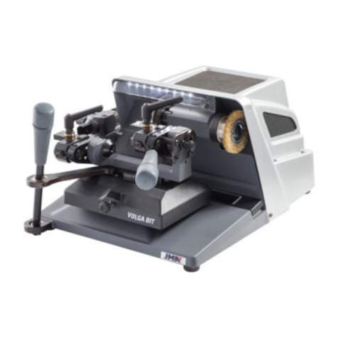
JMA VOLGA BIT User manual

VOLGA BIT
www.jma.es
MÁQUINA DUPLICADORA
MANUAL DE INSTRUCCIONES
KEY CUTTING MACHINE
MUSER MANUAL
SCHLÜSSELKOPIERFRÄSE
ANWEISUNGSHANDBUCH
MACHINE A REPRODUIRE
MANUEL D’INSTRUCTIONS
MÁQUINA DUPLICADORA
MANUAL DE INSTRUÇÕES
MASZYNA DO KOPIOWANIA


ESPAÑOL
VOLGA-BIT
MANUAL DE INSTRUCCIONES
MÁQUINA DUPLICADORA

Español
4
1 PRESENTACIÓN Y ASPECTOS GENERALES
1.1 GENERALIDADES
1.2 TRANSPORTE Y EMBALAJE
1.3 ETIQUETA IDENTIFICADORA
2 CARACTERÍSTICAS DE LA MÁQUINA
2.1 ACCESORIOS
2.2 CIRCUITO ELÉCTRICO
2.3 DATOS TÉCNICOS
2.4 NOMENCLATURA DE LA LLAVE
2.5 ELEMENTOS PRINCIPALES DE LA MÁQUINA
2.6 COMPONENTES Y PARTES FUNCIONALES
2.6.1 Mordaza
2.6.2 Bloqueo del giro de la mordaza derecha
2.6.3 Contrapuntos (modo de utilización)
2.6.4 Longitud máxima de llave
2.6.5 Muelleo del palpador
2.6.6 Bloqueo del eje X
2.6.7 Bloqueo del eje Y
2.6.8 Carro REGATA (opcional)
3 OPERATIVIDAD Y FUNCIONAMIENTO
3.1 REGLAJES
3.1.1 Reglaje lateral
3.1.2 Reglaje de profundidad de corte
3.1.3 Reglaje del Tope Lateral
3.2 CIFRADO
3.2.1 Cifrado de llaves tipo GORJA
3.2.2 Cifrado de llaves FRONTALES
3.2.3 Cifrado de cortes VERTICALES
4 MANTENIMIENTO
4.1 SUSTITUCIÓN DE LA FRESA
4.2 SUSTITUCIÓN DEL PALPADOR
4.3 SUSTITUCIÓN DEL CEPILLO
4.4 SUSTITUCIÓN DE LA CORREA
4.5 SUSTITUCIÓN DEL MOTOR
4.6 SUSTITUCIÓN DE LOS FUSIBLES
4.7 SUSTITUCIÓN DE LOS LEDS DE ILUMINACIÓN
4.8 SUSTITUCIÓN DE LA PLACA DE CONEXIONES
5 SEGURIDAD
6 ELIMINACION DE DESECHOS
6.1 EMBALAJE
6.2 VIRUTA
6.3 MAQUINA
7 EXPLOSIONADOS

Español
5
1.- PRESENTACIÓN Y ASPECTOS GENERALES
1.1 GENERALIDADES
La máquina duplicadora VOLGA-BIT se ha diseñado teniendo en cuenta la normativa
de seguridad vigente en la C.E.E.
La seguridad del personal involucrado en el manejo de este tipo de máquinas solo se
consigue con un programa bien diseñado en seguridad personal, como la implantación
de un programa de mantenimiento y el seguimiento de los consejos recomendados,
así como el cumplimiento de las normas de seguridad que contempla este manual.
Aunque la instalación de la máquina no presenta ninguna dificultad, es preferible que
no intente instalar, ajustar o manipular la misma sin leer previamente este manual.
La máquina sale de nuestra fabrica lista para el uso y solo necesita operaciones de
calibrado para los útiles que se vayan a utilizar.
1.2 TRANSPORTE Y EMBALAJE
La máquina VOLGA-BIT se presenta en una caja de cartón robusta protegida con
espuma de embalaje, de las siguientes dimensiones:
Anchura = 570 mm; Profundidad = 570 mm; Altura = 380 mm;
Peso (incluido el embalaje) = 28 Kg.
Cuando desembale la máquina, inspecciónela cuidadosamente por si hubiese sufrido
algún daño durante el transporte.
Si encuentra alguna anomalía, avise inmediatamente al transportista y no haga nada
con la máquina hasta que el agente del transportista haya realizado la inspección
correspondiente.
Para el desplazamiento de la máquina de un lugar a otro, aconsejamos que coja la
máquina sólo por su base y no por otras partes.
1.3 ETIQUETA IDENTIFICADORA
La máquina duplicadora VOLGA-BIT está provista de una etiqueta identificadora, con
especificación del número de serie o matrícula de máquina, nombre y dirección del
fabricante, marca CE y año de fabricación.
2.- CARACTERÍSTICAS DE LA MÁQUINA
La VOLGA-BIT es una moderna máquina duplicadora de llaves tipo gorja y llaves
frontales.
2.1 ACCESORIOS
La máquina se suministra con una serie de accesorios para su uso y mantenimiento:
- 2 contrapuntos para llaves hembra con orificio estrecho
- 2 contrapuntos para llaves hembra con orificio ancho
- 2 contrapuntos para llaves macho especial
- 2 varillas para hacer el reglaje (Ø5x70)
- 1 Varilla para el cambio de fresa o cepillo (7x70)
- 1 Llave fija de 18
- 1 Juego de llaves allen (2, 2.5, 3, 4, 5, 6)
2.2 CIRCUITO ELÉCTRICO
Los componentes principales del circuito eléctrico y electrónico son los siguientes:
1. Toma de corriente
2. Interruptor puesta en marcha (ROJO luminoso)
3. Pulsador para el cepillo (NEGRO)
4. Motor
5. Transformador
6. Diodos LED de
iluminación
7. Placa de conexiones
2.3 DATOS TÉCNICOS
Motor: Monofásico 220V; 50Hz; 0,25Kw; 1.500 rpm (Opcional: 110V; 60Hz; 0,25Kw;
1.500 rpm)
Fresa: FP19 HSS (Ø80x1,4x16)
Velocidad fresa: 750 rpm
Transmisión: Correa estriada
Mordazas: Autocentrantes
Desplazamientos: Guías con jaulas de rodillos
Cursos útiles: X = 62 mm; Y = 47 mm
Iluminación: Led
Dimensiones: Anchura = 370 mm; Profundidad = 460 mm; Altura: 260 mm
Peso: 26 Kg
2.4 NOMENCLATURA DE LA LLAVE
1. Cabeza
2. Caña
3. Paletón
4. Dientes
2.5 ELEMENTOS PRINCIPALES DE LA MÁQUINA
1.- Fresa
2.- Cepillo
3.- Mordaza
4.- Manilla de la mordaza
5.- Mando de avance del carro
6.- Mando de punto redondo
7.- Soporte palpadoR
8.- Indice copiador
9.- Iluminación
10.-Interruptor puesta en marcha
18.- Orificio para el bloqueo del cabezal
9.- Iluminación
19.- Bandeja para viruta
10.-Interruptor puesta en marcha
20.- Toma general de corriente
12
34
5
6
7
8
9
10
11
12
13
14
15
16
17 18
19
20
2.6 COMPONENTES Y PARTES FUNCIONALES
2.6.1 MORDAZA
La mordaza constituye una parte fundamental de la máquina VOLGA-BIT. Ha
sido estudiada para poder duplicar el mayor número posible de llaves, utilizando
contrapuntos para el duplicado de algunas de ellas.
2.6.2 BLOQUEO DEL GIRO DE LA MORDAZA DERECHA
La mordaza del lado derecho del carro BIT dispone de la maneta “16”, que permite el
bloqueo-desbloqueo del giro.
El bloqueo del giro de esta mordaza es útil para:
- Duplicar llaves frontales.
- Facilitar el amarre de las llaves en la mordaza.
- Facilitar la realización de “tope de paletón contra la fresa” (en el caso de
llaves cortas).
2.6.3 CONTRAPUNTOS (MODO DE UTILIZACIÓN)
La máquina VOLGA-BIT dispone de tres parejas de contrapuntos, para facilitar el
amarre de diferentes tipos de llave:
CONTRAPUNTOS DE PUNTA FINA: para llaves HEMBRA con orificio pequeño
Orificio: desde Ø3 hasta Ø4
Caña: mayor que Ø5
CONTRAPUNTOS DE PUNTA GRUESA: para llaves HEMBRA con orificio grande
Orificio: desde Ø4 hasta Ø5,5
Caña: mayor que Ø6
1
234
11.- Pulsador de marcha del cepillo
12.- Mando de regulación en profundidad del palpador
13.- Maneta de fijación del carro
14.- Maneta de bloqueo del carro en la dirección X
15.- Maneta para muelleo del palpador
16.- Maneta de bloqueo del giro de la mordaza
17.- Bandeja para accesorios
18.- Orificio para el bloqueo del cabezal
19.- Bandeja para viruta
20.- Toma general de corriente

Español
6
CONTRAPUNTOS DE ORIFICIO CÓNICO: para llaves MACHO con cabeza de plástico,
Con caña cuadra,…
Caña: mayor que Ø4
La manera correcta de utilizar los contrapuntos, es la siguiente:
1) AMARRAR LA LLAVE:
Amarrar las llaves, de la siguiente manera:
Llave HEMBRA: hacer tope contra el TOPE LATERAL
Llave MACHO: hacer tope FRESA-PALPADOR.
2) MONTAR LOS CONTRAPUNTOS:
Elegir la pareja de contrapuntos, en función del tipo de llave.
NOTA:
Para ayudar a identificarlos, llevan diferentes grabados en el extremo de la cabeza.
El contrapunto se introduce por el interior del casquillo del carro, roscándolo
manualmente. Detener su introducción al notar que ha llegado hasta la llave (NO
FORZAR).
3) SOLTAR LAS LLAVES:
Soltar las llaves, antes de extraer los contrapuntos.
4) EXTRAER LOS CONTRAPUNTOS:
Extraer los contrapuntos, girándolos manualmente.
2.6.4 LONGITUD MÁXIMA DE LLAVE
La máquina VOLGA-BIT ha sido proyectada de manera que no existe limitación en la
longitud de la llave a duplicar.
Dispone de mordazas a dos alturas, de tal manera que la mordaza del lado izquierdo
no impide el amarre de cualquier longitud de llave.
2.6.5 MUELLEO DEL PALPADOR
La máquina VOLGA-BIT dispone de la maneta “15” que acciona el muelleo del
palpador.
El muelleo del palpador facilita la introducción del palpador entre los dientes de la
llave, para el posterior guiado de la llave hacia la fresa.
2.6.6 BLOQUEO DEL EJE X
La máquina VOLGA-BIT dispone de la maneta “14” que bloquea-desbloquea el
movimiento del carro en la dirección X.
La función de bloqueo del eje X es útil cuando queremos que el carro avance de
manera frontal y sin posibilidad de movimientos laterales. También es útil cuando
queremos duplicar llaves con el carro opcional para llaves de REGATA.
El bloqueo del eje X también nos facilita la operación de amarrar-soltar las llaves de
sus mordazas, al impedir que el carro se deslice hacia los lados.
2.6.7 BLOQUEO DEL EJE Y
La máquina también dispone de un leve bloqueo en el final de la carrera del eje Y,
para impedir que el carro se deslice hacia delante durante la operación de amarrar-
soltar las llaves de sus mordazas.
Basta con llevar el carro de la máquina hasta su posición más extrema en dirección
hacia el usuario, para que notemos como el carro queda bloqueado por medio de un
pequeño resorte.
Para desbloquear el carro, basta con empujar levemente hacia delante la palanca de
traslación del carro.
2.6.8 CARRO REGATA (OPCIONAL)
La máquina VOLGA-BIT dispone de un carro especial (de compra opcional), para
poder realizar los cortes verticales de algunos modelos de llaves. Se denomina carro
REGATA.
Para intercambiar los carros BIT y REGATA, la máquina dispone de la maneta “13”,
que bloquea-desbloquea los carros.
Antes de realizar la operación de intercambio de carros, resulta muy útil bloquear los
ejes X e Y de la máquina.
Los carros se extraen e introducen por la parte derecha de la máquina.
3.- OPERATIVIDAD Y FUNCIONAMIENTO
3.1 REGLAJES
La máquina duplicadora VOLGA-BIT sale reglada de fábrica. Sin embargo, se
recomienda realizar algunos reglajes tras alguna de las siguientes situaciones:
- Tras un reemplazo de fresa, palpador o mordaza.
- Tras un prolongado tiempo de uso.
3.1.1 REGLAJE LATERAL
• Bloquear el giro de la mordaza del lado derecho, actuando sobre la maneta “16”.
• Amarrar una llave virgen del tipo frontal, en la mordaza del lado derecho.
• Acercar la zona central de la llave, hacia la fresa.
• Bloquear el eje X del carro, actuando sobre la maneta “14”.
• Ejecutar un ranurado recto de aproximadamente 8 mm. de profundidad.
16
• Soltar la llave de la mordaza del lado derecho y amarrarla en la mordaza del
lado izquierdo.
• Aflojar ligeramente los dos tornillos “L” que amarran el Soporte palpador “7”.
• Desplazar el soporte palpador “7” hacia la izquierda o derecha, hasta lograr
que el palpador se introduzca en la ranura que anteriormente hemos realizado
en la llave.
• En esta posición, fijar el soporte palpador “7” por medio de los dos tornillos “L”.
• Ahora ya se puede desbloquear el eje X del carro, actuando sobre la maneta “14”
7
L
L
3.1.2 REGLAJE DE PROFUNDIDAD DE CORTE
• Bloquear el giro de la mordaza del lado derecho, actuando sobre la maneta “16”.
• Amarrar las varillas de reglaje en las mordazas.
• Desbloquear el giro de la maneta “12”, aflojando el tornillo “M”.
• Activar el muelleo del palpador, actuando sobre la maneta “15”.
• Desplazar el carro hacia adelante, de manera que las varillas de reglaje se
apoyen en el Palpador “T” y en la Fresa “C”.

Español
7
• Actuando sobre la maneta “12”, desplazar el Palpador hacia adelante o hacia
atrás, hasta lograr que estando el Palpador “T” apoyado sobre la varilla de
reglaje “VT”, la Fresa “C” roce ligeramente la varilla de reglaje “VC”.
• Volver a apretar el tornillo “M”.
16
12
M
15
T
C
VT
VC
3.1.3 REGLAJE DEL TOPE LATERAL
• El carro BIT se suministra con los Topes Laterales regulados de fábrica, por lo
que NO es necesario volver a ajustarlos.
• Sin embargo, tras una sustitución de los Topes Laterales, el modo de regularlos
sería el siguiente:
• Apoyar el lateral derecho del Tope Lateral “N1”, contra el casquillo interno “C1”
• En esta posición, apretar el tornillo “R” para fijar el Tope Lateral “N1”.
• Amarrar una llave del tipo “macho larga” en la mordaza del lado derecho, de
manera que el paletón haga tope contra el Tope Lateral “N1”.
• Bloquear el eje “X” del carro, actuando sobre la maneta “14”.
• Ejecutar un ranurado recto de aproximadamente 8 mm. de profundidad.
N1
R
C1
• Aflojar el tornillo “Q” que fija el casquillo interno “C2”.
• Soltar la llave de la mordaza del lado derecho y amarrarla en la mordaza del
lado izquierdo, de tal manera que el palpador “T” se introduzca en la ranura que
hemos realizado en la llave.
• En esta posición de la llave, apoyar el lateral izquierdo del Tope Lateral “N2”,
contra el paletón de la llave.
• En esta posición del Tope Lateral “N2”, apretar el tornillo “R” para fijar el Tope
Lateral “N2”.
• Desplazar el casquillo interno “C2”, hasta que toque en el lateral derecho del
Tope Lateral “N2”.
• En esta posición del casquillo interno “C2”, bloquearlo por medio del tornillo “Q”.
• Ahora ya se puede desbloquear el eje X del carro, actuando sobre la maneta “14”
N2 C2
Q
T
R
3.2 CIFRADO
3.2.1 CIFRADO DE LLAVES TIPO GORJA
Amarrar la llave en la mordaza. Dependiendo del tipo de llave que queramos duplicar,
el tope de la llave se hará de una de las siguientes maneras:
Llave con tope en la caña:
Tope contra el lateral izquierdo de la mordaza.
Llave CORTA (macho/hembra) (simple/doble paletón):
Tope del lateral derecho del paletón contra el lateral izquierdo de la Feresa y del
Palpador.
Llave LARGA MACHO (simple/doble paletón):
Tope contra el Tope Lateral.
Llave LARGA HEMBRA (simple/doble paletón):
Tope contra el Tope Lateral. Utilizar contrapuntos para hembra.
- Llave MACHO ESPECIAL: con cabeza de plástico, con caña cuadrada, …… :
Tope Fresa-Palpador. Utilizar contrapuntos para macho.
• Para mayor comodidad a la hora de amarrar las llaves en las mordazas, se
recomienda bloquear el eje X y el eje Y (de esta manera, el carro de la máquina
se mantiene quieto). También se recomiendo bloquear el giro de la mordaza
derecha, para facilitar la orientación del paletón de la llave.
• Poner en marcha el giro de la fresa, accionando el correspondiente interruptor.
• Acercar con cuidado las llaves hacia la Fresa y el Palpador. Recomendamos
trabajar pausadamente, sin forzar la fresa.
• El punto redondo se consigue girando la palanca “6” (moviendo la palanca
desde arriba hacia abajo). Este giro está limitado internamente. En el caso de
dientes profundos situados en el extremo derecho del paletón, limitar el giro de
la palanca para que la fresa no toque el Tope Lateral.
• Para las llaves de doble paletón, girar ambas llaves 180º y repetir las
operaciones ya descritas.
• Si durante el duplicado se producen rebabas en la llave duplicada, éstas se
eliminarán utilizando el cepillo que para este fin se ha dotado a la máquina.

Español
8
3.2.2 CIFRADO DE LLAVES FRONTALES
• Bloquear el giro de la mordaza derecha. Para ello, accionar la maneta “16”.
• Colocar la llave en la garganta transversal de la mordaza.
• Colocar la llave de manera que el paletón asimétrico respecto de la caña, quede
mirando hacia abajo.
• Empujar la llave hasta que la parte trasera del paletón haga tope contra la cara
anterior de la mordaza.
• Es importante que el paletón de la llave quede lo más horizontal posible.
• Teniendo en cuenta estos detalles, amarrar las llaves en las mordazas.
• Para mayor comodidad a la hora de amarrar las llaves en las mordazas, se
recomienda bloquear el eje X y el eje Y (de esta manera, el carro de la máquina
se mantiene quieto).
• Poner en marcha el giro de la fresa, accionando el correspondiente interruptor.
• Acercar las llaves hacia la Fresa y el Palpador. Recomendamos trabajar
pausadamente, sin forzar la fresa.
• Si durante el duplicado se producen rebabas en la llave duplicada, éstas se
eliminarán utilizando el cepillo.
3.2.3 CIFRADO DE CORTES VERTICALES
• Reemplazar el carro BIT por el carro REGATA.
• Para mayor comodidad a la hora de intercambiar estos carros, se recomienda
bloquear el eje X y el eje Y de la máquina. De esta manera, el carro principal de
la máquina se mantiene quieto.
• Los carros BIT y REGATA se sueltan y amarran mediante el accionamiento de la
maneta “13”.
• El carro BIT se extrae tirando de él hacia el lado derecho.
• El carro REGATA se introduce de derecha a izquierda, hasta que se sienta un
tope interno.
• Amarrar la llave virgen y la llave a cifrar en sus correspondientes mordazas,
actuando sobre las manetas “S”.
• El paletón de la llave debe hacer tope contra la parte inferior de la mordaza.
• El paletón de la llave debe apoyar contra la pared vertical de la mordaza.
• Poner en marcha el giro de la fresa, accionando el interruptor correspondiente.
• Con la palanca “W” en su posición más superior, acercar las llaves a la Fresa
“C” y al Palpador “T”.
• Introducir el Palpador en la ranura de la llave a duplicar.
• Desplazar suavemente la palanca “W” hacia abajo. Recomendamos trabajar
pausadamente, sin forzar la fresa.
• Repetir esta misma operación, las veces necesarias hasta completar el cifrado
de los cortes verticales de la llave.
• Si durante el cifrado se producen rebabas en la llave duplicada, éstas se
eliminarán utilizando el cepillo.
4.- MANTENIMIENTO
A la hora de ejecutar cualquier operación de mantenimiento, es necesario cumplir los
siguientes requisitos:
• Nunca se debe efectuar ninguna operación con la máquina en marcha.
• El cable de alimentación, se debe desconectar de la conexión eléctrica.
• Se han de seguir estrictamente las indicaciones de este manual.
• Utilizar piezas originales de repuesto.
4.1 SUSTITUCIÓN DE LA FRESA
Para sustituir la fresa, proceder de la siguiente manera:
• Apagar y desenchufar la máquina.
• Introducir la varilla “A” que se suministra junto con los accesorios, en el orificio
que bloquea el giro del cabezal. Para buscarlo, girar el cabezal con la mano.
• Con la llave fija “B” que también se suministra junto con los accesorios, soltar
la tuerca “E”. Tener en cuenta que la tuerca “E” es de rosca izquierdas.
• Extraer la fresa “C” desgastada.
• Instalar la nueva fresa “C”, y amarrarla apretando la tuerca “E”. Revisar que
la fresa quede montada con sus dientes de corte orientados en la posición
correcta. Tener en cuenta que la fresa gira en sentido horario.
• Extraer la varilla “A”.
• Tras la sustitución de la fresa, se recomienda realizar el “Reglaje de
profundidad de corte”. El procedimiento se indica en el punto 3.1.2 del presente
Manual.
ABC
E
4.2 SUSTITUCIÓN DEL PALPADOR
Para sustituir el palpador, proceder de la siguiente manera:
• Apagar y desenchufar la máquina.
• Soltar el tornillo “F”, utilizando la llave allen del nº4 que se suministra junto con
los accesorios.
• Extraer el palpador “T” desgastado.
• Instalar el nuevo palpador “T”. Asegurándose de que la parte trasera del
palpador apoya contra el soporte “G”, apretar el tornillo “F”.
• Tras la sustitución del palpador, se recomienda realizar el “Reglaje de
profundidad de corte”. El procedimiento se indica en el punto 3.1.2 del presente
Manual.
G
T
F
4.3 SUSTITUCIÓN DEL CEPILLO
Para sustituir el cepillo, proceder de la siguiente manera:
• Apagar y desenchufar la máquina.
• Introducir la varilla “A” que se suministra junto con los accesorios, en el orificio
que bloquea el giro del cabezal. Para buscarlo, girar el cabezal con la mano.
• Soltar el tornillo “H”, utilizando la llave allen del nº4 que se suministra junto con
los accesorios.
• Extraer el cepillo “J” desgastado.
• Instalar el nuevo cepillo “J” y amarrarlo apretando el tornillo “H”. No apretarlo
con mucha fuerza, para que en la próxima sustitución del cepillo, el tornillo “H”
se pueda soltar con cierta facilidad.
• Extraer la varilla “A”.
•
SS
W
T
C

Español
9
A J H
4.4 SUSTITUCIÓN DE LA CORREA
La correa de la máquina VOLGA-BIT es elástica, por lo que no requiere operaciones de
tensado.
En caso de ser necesario la sustitución de la correa, proceder de la siguiente manera:
• Apagar y desenchufar la máquina.
• Retirar el carro de la máquina (BIT o REGATA).
• Retirar la alfombrilla “K” de la parte superior.
• Retirar la cubierta “N” que oculta el motor. Para ello, soltar los 11 tornillos que
lo sujetan a la Bancada.
• Retirar la chapa “O”. Para ello, soltar los 2 tornillos.
• Retirar el cepillo “J”. El procedimiento se indica en el punto 4.3 del presente
Manual.
• Retirar la vieja correa “I”. Para extraerla de las poleas, girar manualmente la
correa a la vez que la forzamos sobre el lateral.
• Montar la nueva correa. Para ello, orientar la máquina de manera que la parte
trasera quede frente a nosotros. En primer lugar, introducir la correa en la polea
del motor. Luego, colocar el otro extremo de la correa sobre el diámetro del
lateral de la polea del cabezal. Por último, forzar lateralmente la correa mientras
giramos el cabezal con la llave del nº13 introducida en la tuerca de la fresa.
• Verificar que la correa esté montada correctamente.
4.5 SUSTITUCIÓN DEL MOTOR
Para sustituir el motor, proceder de la siguiente manera:
• Apagar y desenchufar la máquina.
• Retirar la correa “I”. El procedimiento se indica en el punto 4.4 del presente
manual.
• Retirar la chapa de protección inferior “P”. Para ello, soltar los 8 tornillos que la
sujetan a la bancada.
• Desenchufar el cable de alimentación del motor.
• Retirar el motor “Z”. Para ello, soltar los 4 tornillos que sujetan la base del
motor a la bancada.
• Extraer la polea “Y”. Para ello, soltar el tornillo prisionero “X”.
• Para montar el nuevo motor, efectuar las mismas operaciones descritas, pero de
forma inversa.
4.6 SUSTITUCIÓN DE LOS FUSIBLES
En el caso de que la máquina no se ponga en marcha cuando se accionan los
interruptores de marcha, es necesario comprobar el estado de los fusibles.
Esta operación se realiza de la siguiente manera:
• Apagar y desenchufar la máquina.
• Con ayuda de un pequeño destornillador, extraer el portafusibles “U” de la toma
de corriente.
• Verificar los fusibles con un tester, ya que a vista puede parecer que se
encuentran en buenas condiciones, incluso cuando están eléctricamente
defectuosos.
• En caso de necesidad, reemplazar los fusibles por otros del mismo tipo y valor.
4.7 SUSTITUCIÓN DE LOS LEDS DE ILUMINACIÓN
Para sustituir los LED de iluminación, proceder de la siguiente manera:
• Apagar y desenchufar la máquina.
• Retirar el carro de la máquina (BIT o REGATA).
• Retirar la alfombrilla “K” de la parte superior.
• Retirar la cubierta “N” que oculta el motor. Para ello, soltar los 11 tornillos que
lo sujetan a la Bancada.
• Retirar la fresa “C”. El procedimiento se indica en el punto 4.1 del presente
Manual.
• Retirar el protector de la fresa “D”. Para ello, soltar los 3 tornillos que lo sujetan
a la bancada.
• Desatornillar los 2 cables de la tira de leds “9”, de la regleta de conexiones.
• Despegar la tira de leds “9” del soporte en el que se encuentra pegado.
• Extraer la tira de leds “9”, de manera que sus cables salgan por el orificio del
soporte.
• Para montar la nueva tira de leds “9”, efectuar las mismas operaciones
descritas, pero de forma inversa.
K
N
C
D
9
U
P
Z
Y
X
K
N
J
IO
4.4
4.5
4.6
4.7

Español
10
4.8 SUSTITUCIÓN DE LA PLACA DE CONEXIONES
Para sustituir la placa de conexiones, proceder de la siguiente manera:
• Apagar y desenchufar la máquina.
• Retirar el carro de la máquina (BIT o REGATA).
• Retirar la alfombrilla “K” de la parte superior.
• Retirar la cubierta “N” que oculta el motor. Para ello, soltar los 11 tornillos que
lo sujetan a la Bancada.
K
N
• Girar la máquina y apoyarla sobre el lado derecho, para disponer de acceso a la
parte inferior de la máquina.
• Retirar la chapa de protección inferior “P”. Para ello, soltar los 8 tornillos que la
sujetan a la bancada.
• Desconectar los 3 conectores de la placa de conexiones “V”, anotando
previamente la posición de cada uno.
• Retirar la placa de conexiones “V”. Para ello, desatornillar los 4 tornillos “L2”
que la sujetan.
• Para montar la nueva placa de conexiones “V”, efectuar las mismas operaciones
descritas, pero de manera inversa.
P
L2 V
5.- SEGURIDAD
Por su seguridad, le recomendamos que siga las siguientes pautas:
No intente poner en marcha o manipular la máquina, hasta que todos los temas de
seguridad, instrucciones para la instalación, guía del operario y procedimientos de
mantenimiento, hayan sido cumplimentados y entendidos.
Desconecte siempre el suministro eléctrico, antes de realizar cualquier trabajo de
limpieza o mantenimiento.
Mantenga la máquina siempre limpia, así como su entorno.
Trabajar con las manos secas.
Utilizar siempre gafas de protección, aunque la máquina ya disponga de protecciones.
Asegúrese de que la máquina tenga toma a tierra.
Recomendamos trabajar con la máquina a una altura en la cuál el usuario se
encuentre cómodo.
6.- ELIMINACION DE DESECHOS
Por desecho se entiende cualquier sustancia u objeto procedente de actividades
humanas o de ciclos naturales, abandonada o destinada a ser abandonada.
6.1 EMBALAJE
Como el embalaje en el que se suministra la NEO es de cartón, el mismo se podría
reciclar como embalaje.
Como desecho, se equipara a los desechos sólidos urbanos y por lo tanto no se puede
tirar más que en los contenedores especiales para cartón.
Los cascos que protegen la máquina dentro de la caja de cartón, son de material
polimérico equiparable a los desechos sólidos urbanos y por lo tanto, no se pueden
eliminar más que en las instalaciones normales de eliminación de desechos.
6.2 VIRUTA
Los residuos procedentes de la duplicación de llaves, están clasificados como
desechos especiales, pero se equiparan a los desechos sólidos urbanos, como
por ejemplo un estropajo metálico. Estos desechos se eliminarán según como los
clasifiquen las leyes vigentes en la UE, entregándolos en las instalaciones especiales
de eliminación de desechos.
6.3 MAQUINA
Antes de efectuar la demolición de la máquina, es preciso ponerla fuera de servicio,
cortando el suministro de energía eléctrica y separando las piezas de plástico de las
piezas metálicas.
Tras efectuar esta operación, se podrán eliminar todos los desechos, en conformidad
con las leyes en vigor en el país donde se utiliza la máquina.

ENGLISH
VOLGA-BIT
USER MANUAL
KEY CUTTING MACHINE

ENGLISH
1.- PRESENTATION AND GENERAL ASPECTS
1.1 GENERAL INFORMATION
1.2 TRANSPORTATION AND PACKAGING
1.3 IDENTIFYING LABEL
2.- MACHINE FEATURES
2.1 ACCESSORIES
2.2 ELECTRIC CIRCUIT
2.3 TECHNICAL DATA
2.4 NOMENCLATURE OF THE KEY
2.5 MAIN ELEMENTS OF THE MACHINE
2.6 COMPONENTS AND FUNCTIONAL PARTS
2.6.1 Clamp
2.6.2 Rotation lock of the right-hand side clamp
2.6.3 Counterpoints (use mode)
2.6.4 Maximum length of key
2.6.5 Probe spring
2.6.6 Lockage of the X axis
2.6.7 Y axis locking
2.6.8 Clamp carriage for vertical cuts (optional)
3.- OPERATION AND FUNCTION
3.1 ADJUSTMENTS
3.1.1 Side adjustment
3.1.2 Cutting depth adjustmen
3.1.3 Lateral Stop Adjustment
3.2 ENCRYPTION
3.2.1 Encryption of the MORTISE keys
3.2.2 Encryption of FRONTAL keys
3.2.3 Encryption of VERTICAL cuts
4.- MAINTENANCE
4.1 REPLACEMENT OF THE CUTTER
4.2 REPLACING THE PROBE
4.3 BRUSH REPLACEMENT
4.4 REPLACEMENT OF THE BELT
4.5 MOTOR REPLACEMENT
4.6 REPLACING THE FUSES
4.7 REPLACING THE LIGHTING LEDS
4.8 REPLACEMENT OF THE CONNECTION PLATE
5.- SAFETY
6.- WASTE DISPOSAL
6.1 PACKAGING
6.2 SHAVINGS
6.3 MACHINE
7.- EXPLODED VIEW DRAWING

english
13
1.- MACHINE OVERVIEW
1.1 GENERAL ASPECTS
The VOLGA-BIT cutting machine has been designed taking into account the safety
regulations in force in the EEC.
The safety of the personnel involved in the handling of this type of machine is
only achieved with a well-designed personal safety programme, such as the
implementation of a maintenance programme and follow-up to the recommended
advice, as well as compliance with safety regulations contained in this manual.
Although the installation of the machine presents no difficulty, it is preferable that you
do not attempt to install, adjust or handle it without reading this manual first.
The machine leaves our factory ready for use and only needs calibration operations for
the tools that are going to be used.
1.2 TRANSPORTATION AND PACKAGING
The VOLGA-BIT machine is presented in a sturdy cardboard box protected with
packaging foam, of the following dimensions:
Width = 570 mm; Depth = 570 mm; Height = 380 mm;
Weight (including packaging) = 28 Kg.
When unpacking the machine, carefully inspect it for any damage during transport.
If you find any anomaly, immediately notify the carrier and do nothing with the
machine until the carrier’s agent has carried out the corresponding inspection.
To move the machine from one place to another, we recommend that you only lift the
machine by its base and not by other parts.
1.3 IDENTIFYING LABEL
The VOLGA-BIT cutting machine comes with an identifying label, with specification of
the serial number or machine registration, name and address of the manufacturer, CE
mark and year of manufacture.
2 MACHINE FEATURES
The VOLGA-BIT is a modern cutting machine for mortise-type keys and frontal keys.
2.1 ACCESSORIES
The machine is supplied with a series of accessories for its use and maintenance:
- 2 Counterpoints for female keys with narrow holes
- 2 Counterpoints for female keys with wide holes
- 2 Counterpoints for special male keys
- 2 Rods to make the adjustment (Ø5x70)
- 1 Rod for the change of cutter or brush (7x70)
- 1 Fixed key of 18
- 1 Set of Allen keys (2, 2.5, 3, 4, 5, 6)
2.2 ELECTRICAL CIRCUIT
The main components of the electrical and electronic circuit are the following:
1. Plug
2. Start switch (RED light)
3. Push button for brush (BLACK)
4. Motor
5. Transformer
6. LED lighting diodes
7. Connection plate
2.3 TECHNICAL DATA
Motor: Single phase 220V; 50Hz; 0,25Kw; 1,500 rpm (Optional: 110V; 60Hz; 0,25Kw;
1,500 rpm)
Cutter: FP19 HSS (Ø80x1.4x16)
Cutter speed: 750 rpm
Transmission: Ribbed belt.
Clamps: Self-centring
Movements: Guides with roller cages
Useful courses: X = 62 mm; Y = 47 mm
Lights: Led
Dimensions: Width = 370 mm; Depth = 460 mm; Height: 260 mm
Weight: 26 Kg
2.4 NOMENCLATURE OF THE KEY
1. Head
2. Stem
3. Bit
4. Teeth
2.5 MAIN ELEMENTS OF THE MACHINE
1.- Cutter
2.- Brush
3.- Clamp
4.- Clamp handle
5.- Carriage forward control
6.- Round point control
7.- Probe support
8.- Copier index
9.- Lighting
10.-Start-up switch
12
34
5
6
7
8
9
10
11
12
13
14
15
16
17 18
19
20
2.6 COMPONENTS AND FUNCTIONAL PARTS
2.6.1 CLAMP
The clamp is a fundamental part of the VOLGA-BIT machine. It has been studied to be
able to cut as many keys as possible, using counterpoints for the cutting of some of
them.
2.6.2 ROTATION LOCK OF THE RIGHT-HAND SIDE CLAMP
The clamp on the right side of the BIT carriage has the handle “16”, which allows the
locking and unlocking of the rotation.
Locking the rotation of this clamp is useful for:
• Copying frontal keys.
• Facilitating the fastening of the keys in the clamp.
• Facilitating the realization of the “bit stop against the cutter” (in the case of
short keys).
2.6.3 COUNTERPOINTS (USE MODE)
The VOLGA-BIT machine has three pairs of counterpoints, to facilitate the attachment
of different types of keys:
1
234
11.- Push button of the brush
12.- Adjustment control in depth of the probe
13.- Carriage fixing handle
14.- Carriage locking handle in the X direction
15.- Handle for the probe’s spring
16.- Grip lock handle of the clamp
17.- Tray for accessories
18.- Hole for locking the head
19.- Chip tray
20.- General power socket

english
14
FINE POINT COUNTERPOINTS: for FEMALE keys with a small hole
Hole: from Ø3 to Ø4 Stem: greater than Ø5
THICK POINT COUNTERPOINT: for FEMALE keys with a large hole
Hole: from Ø4 to Ø5.5 Stem: greater than Ø6
TAPERED HOLE COUNTERPART: for MALE keys with plastic head, with square stem, ...
Stem: greater than Ø4
The correct way to use the counterpoints, is the following:
1) FASTEN THE KEY:
Fasten the keys, as follows:
FEMALE key: make a stop against the LATERAL STOP
MALE key: make a stop against the CUTTER-PROBE.
2) FIT THE COUNTERPOINTS:
Choose the pair of counterpoints, depending on the type of key.
NOTE: To help identify them, they have different engravings on the end of the head.
The counterpoint is inserted inside the carriage bushing, manually threading it. Stop
inserting it when you see it has reached as far as the key (DO NOT FORCE IT).
3) RELEASE THE KEYS:
Release the keys, before removing the counterpoints.
4) REMOVE THE COUNTERPOINTS:
Remove the counterpoints, turning them manually.
2.6.4 MAXIMUM LENGTH OF KEY
The VOLGA-BIT machine has been designed in such a way that there is no limitation
on the length of the key to be cut.
It has clamps at two heights, in such a way that the clamp on the left side does not
prevent the attachment of any key length.
2.6.5 PROBE SPRING
The VOLGA-BIT machine has the handle “15” that activates the probe’s spring.
The probe spring facilitates the insertion of the probe between the teeth of the key,
for the subsequent guidance of the key towards the cutter.
2.6.6 LOCKAGE OF THE X AXIS
The VOLGA-BIT machine has the handle “14” that locks-unlocks the movement of the
carriage in the X direction.
The locking function of the X axis is useful when we want the carriage to move
forward and without the possibility of lateral movements. It is also useful when we
want to cut keys with the optional clamp carriage for vertical cuts.
Locking the X axis also facilitates the operation of fastening-releasing the keys from
its clamps, by preventing the carriage from sliding to the sides.
2.6.7 Y AXIS LOCKING
The machine also has a slight lock at the end of the course of the Y axis, to prevent
the carriage from sliding forward during the operation of fastening-releasing the keys
from its clamps.
Just bring the carriage of the machine to its most extreme position towards the user,
so that we can see that the carriage is locked by means of a small spring.
To unlock the carriage, simply push the carriage lever forward slightly.
2.6.8 CLAMP CARRIAGE FOR VERTICAL CUTS (OPTIONAL)
The VOLGA-BIT machine has a special carriage (optional purchase), to make vertical
cuts of some models of keys. It is called clamp carriage for vertical cuts.
To swap the BIT carriage and the clamp carriage for vertical cuts, the machine has the
handle “13”, which locks-unlocks the carriage.
Before performing the carriage swap operation, it is very useful to lock the X and Y
axes of the machine.
The carriages are removed and inserted on the right side of the machine.
3 OPERATION AND FUNCTION
3.1 ADJUSTMENTS
The VOLGA-BIT cutting machine is adjusted from the factory. However, it is advisable
to make some adjustments after any of the following situations:
• After replacing a cutter, probe or clamp.
• After a long period of use.
3.1.1 SIDE ADJUSTMENT
• Lock the rotation of the clamp on the right side, operating the handle “16”.
• Tie a frontal virgin key, in the right-side clamp.
• Move the central area of the key towards the cutter.
• Lock the X axis of the carriage, operating the handle “14”.
• Execute a straight groove of approximately 8 mm. of depth.
16
• Release the key on the right-side clamp and fasten it on the left side clamp.
• Slightly loosen the two “L” screws that secure the probe support “7”.
• Move the probe support “7” to the left or right, until the probe is inserted into
the slot that we previously made in the key.
• In this position, fasten the probe support “7” by means of the two “L” screws.
• Now you can unlock the X axis of the carriage, operating the handle “14”
7
L
L

english
15
3.1.2 CUTTING DEPTH ADJUSTMENT
• Lock the rotation of the clamp on the right side, operating the handle “16”.
• Fasten the adjustment rods in the clamp.
• Unlock the rotation of the handle “12”, loosening the screw “M”.
• Activate the probe spring, acting on handle “15”.
• Move the carriage forward, so that the adjustment rods rest on the “T” probe
and the “C” cutter.
• Operating the handle “12”, move the probe forward or backward, until the
probe “T” is resting on the adjusting rod “VT”, the “C” cutter lightly rubs the
adjustment rod “VC”.
• Re-tighten the “M” screw.
16
12
M
15
T
C
VT
VC
3.1.3 LATERAL STOP ADJUSTMENT
• The BIT carriage is supplied with the factory-set Lateral Stops, so it is NOT
necessary to adjust them again.
• However, after replacing the Lateral Stops, the way to set them would be as
follows:
• Support the right side of the Lateral Stop “N1”, against the internal bushing
“C1”
• In this position, tighten the “R” screw to fix the Lateral Stop “N1”.
• Attach a “long male” type key to the right-side clamp, so that the bit is butted
against the Lateral Stop “N1”.
• Lock the “X” axis of the carriage, operating the handle “14”.
• Execute a straight groove of approximately 8 mm. of depth.
N1
R
C1
• Loosen the screw “Q” that fixes the internal bushing “C2”.
• Release the key on the right-hand side clamp and attach it to the left side clamp,
so that the “T” probe is inserted into the slot that we have made in the key.
• In this key position, support the left side of the lateral stop “N2”, against the bit
of the key.
• In this position of the Lateral Stop “N2”, tighten the screw “R” to fix the Lateral Stop
“N2”.
• Move the inner bushing “C2”, until it touches the right-side of the Lateral Stop “N2”.
• In this position of the internal bushing “C2”, lock it by means of the “Q” screw.
• Now you can unlock the X axis of the carriage, operating the handle “14”
N2 C2
Q
T
R
3.2 ENCRYPTION
3.2.1 ENCRYPTION OF THE MORTISE KEYS
Fasten the key in the clamp. Depending on the type of key we want to cut, the stop of
the key will be made in one of the following ways:
- Key with stop on the stem:
Stop against the left side of the clamp.
- SHORT key (male/female) (simple/double probe):
Stop of the right side of the bit against the side left of the Cutter and the Probe.
- LONG MALE key (simple/double probe):
Stop against the Lateral Stop.
- LONG FEMALE key (simple/double probe):
Stop against the Lateral Stop. Use counterpoints for female key.
-SPECIAL MALE key: with plastic head, with square stem, ......:
Cutter-Probe Stop. Use counterpoints for male key.
• For greater comfort when fastening the keys in the clamps, it is recommended
to lock the X axis and the Y axis (in this way, the machine carriage stays still).
It is also recommended to lock the rotation of the right clamp, to facilitate the
orientation of the key bit.
• Start the rotation of the cutter, activating the corresponding switch.
• Carefully bring the keys towards the Cutter and the Probe. We recommend
working slowly, without forcing the cutter.
• The round point is achieved by turning the lever “6” (moving the lever from top
to bottom). This rotation is internally limited. In the case of deep teeth located
on the right end of the bit, limit the rotation of the lever so that the bit does not
touch the Lateral Stop.
• For double-bit keys, turn both keys 180º and repeat the operations already
described.
• If during cutting, burrs are produced in the cut key, these will be eliminated
using the brush that has been provided with the machine for this purpose.

english
16
3.2.2 ENCRYPTION OF FRONTAL KEYS
• Lock the rotation of the right-hand side clamp. To do this, operate handle “16”.
• Place the key in the throat cross-section of the clamp.
• Place the key so that the asymmetric bit is facing downwards of the clamp.
• Push the key until the back part of the bit reaches the front face of the clamp.
• It is important that the key bit is as horizontal as possible.
• Keeping these details in mind, fasten the keys in the clamps.
• For greater comfort when fastening the keys in the clamps, it is recommended
to lock the X axis and the Y axis (in this way, the machine carriage stays still).
• Start the rotation of the cutter, activating the corresponding switch.
• Bring the keys towards the Cutter and the Probe. We recommend working
slowly, without forcing the cutter.
• If during cutting, burrs are produced in the cut key, these will be eliminated
using the brush.
3.2.3 ENCRYPTION OF VERTICAL CUTS
• Replace the BIT carriage with the clamp carriage for vertical cuts.
• For greater comfort when changing these carriages, it is recommended to lock
the X axis and the Y axis of the machine. This way, the main carriage of the
machine remains still.
• The BIT carriage and the clamp carriage for vertical cuts are released and
fastened by means of the handle “13”.
• The BIT carriage is pulled out by pulling it to the right side.
• The clamp carriage for vertical cuts is introduced from right to left, until an
internal stop is felt.
• Fasten the virgin key and the key to be encrypted in its corresponding clamps,
operating the “S” handles.
• The bit of the key must stop against the lower part of the clamp.
• The key bit must rest against the vertical wall of the clamp.
• Start the rotation of the cutter, activating the corresponding switch.
• With the lever “W” in its highest position, bring the keys to the cutter “C” and “T” probe.
• Insert the probe into the groove of the key to be cut.
• Gently move lever “W” downwards. We recommend working slowly, without
forcing the cutter.
• Repeat this same operation, as many times as necessary until completing the
encryption of the vertical cuts of the key.
• If during encryption, burrs are produced in the cut key, these will be eliminated
using the brush.
4 MAINTENANCE
When executing any maintenance operation, it is necessary to complete the following
requirements:
• Never carry out any operation while the machine is running.
• The power cable must be disconnected from the electrical connection.
• The instructions in this manual must be followed strictly.
• Use original spare parts.
4.1 REPLACEMENT OF THE CUTTER
To replace the cutter, proceed as follows:
• Turn off and unplug the machine.
• Insert rod “A” supplied with the accessories into the hole that blocks the
rotation of the head. To find it, turn the head by hand.
• With the fixed key “B” which is also supplied together with the accessories,
loosen nut “E”. Take into account that nut “E” has a left-handed thread.
• Remove the worn cutter “C”.
• Install the new cutter “C”, and tighten it by tightening nut “E”. Check that the
cutter is mounted with its cutting teeth pointed in the correct position. Take into
account that the cutter rotates clockwise.
• Remove rod “A”.
• After replacing the cutter, it is recommended to carry out the “Cutting depth
adjustment”. This procedure is indicated in section 3.1.2 of this Manual.
ABC
E
4.2 REPLACING THE PROBE
To replace the probe, proceed as follows:
• Turn off and unplug the machine.
• Loosen screw “F”, using Allen key number 4 supplied with the accessories.
• Remove the worn “T” probe.
• Install the new “T” probe. Make sure that the rear part of the probe rests
against the support “G”, and tighten screw “F”.
• After replacing the probe, it is recommended to carry out the “Cutting depth
adjustment”. This procedure is indicated in section 3.1.2 of this Manual.
G
T
F
4.3 BRUSH REPLACEMENT
To replace the brush, proceed as follows:
• Turn off and unplug the machine.
• Insert rod “A” supplied with the accessories into the hole that blocks the
rotation of the head. To find it, turn the head by hand.
• Loosen screw “H”, using Allen key number 4 supplied with the accessories.
• Remove the worn brush “J”.
• Install the new brush “J” and tighten it by tightening screw “H”. Do not tighten
it too hard, so that in the next replacement of the brush, the “H” screw can be
easily released.
• Remove rod “A”.
SS
W
T
C

english
17
4 MAINTENANCE
When executing any maintenance operation, it is necessary to complete the following
requirements:
• Never carry out any operation while the machine is running.
• The power cable must be disconnected from the electrical connection.
• The instructions in this manual must be followed strictly.
• Use original spare parts.
4.1 REPLACEMENT OF THE CUTTER
To replace the cutter, proceed as follows:
• Turn off and unplug the machine.
• Insert rod “A” supplied with the accessories into the hole that blocks the
rotation of the head. To find it, turn the head by hand.
• With the fixed key “B” which is also supplied together with the accessories,
loosen nut “E”. Take into account that nut “E” has a left-handed thread.
• Remove the worn cutter “C”.
• Install the new cutter “C”, and tighten it by tightening nut “E”. Check that the
cutter is mounted with its cutting teeth pointed in the correct position. Take into
account that the cutter rotates clockwise.
• Remove rod “A”.
• After replacing the cutter, it is recommended to carry out the “Cutting depth
adjustment”. This procedure is indicated in section 3.1.2 of this Manual.
ABC
E
4.2 REPLACING THE PROBE
To replace the probe, proceed as follows:
• Turn off and unplug the machine.
• Loosen screw “F”, using Allen key number 4 supplied with the accessories.
• Remove the worn “T” probe.
• Install the new “T” probe. Make sure that the rear part of the probe rests
against the support “G”, and tighten screw “F”.
• After replacing the probe, it is recommended to carry out the “Cutting depth
adjustment”. This procedure is indicated in section 3.1.2 of this Manual.
G
T
F
4.3 BRUSH REPLACEMENT
To replace the brush, proceed as follows:
• Turn off and unplug the machine.
• Insert rod “A” supplied with the accessories into the hole that blocks the
rotation of the head. To find it, turn the head by hand.
• Loosen screw “H”, using Allen key number 4 supplied with the accessories.
• Remove the worn brush “J”.
• Install the new brush “J” and tighten it by tightening screw “H”. Do not tighten
it too hard, so that in the next replacement of the brush, the “H” screw can be
easily released.
• Remove rod “A”.
A J H
4.4 REPLACEMENT OF THE BELT
The belt of the VOLGA-BIT machine is elastic, so it does not require tensioning
operations.
If replacement of the belt is necessary, proceed as follows:
• Turn off and unplug the machine.
• Remove the carriage from the machine (BIT or Clamp carriage for vertical cuts).
• Remove the “K” mat from the top.
• Remove the “N” cover that hides the motor. To do this, release the 11 screws
that hold it to the bench.
• Remove the “O” sheet. To do this, loosen the 2 screws.
• Remove the “J” brush. This procedure is indicated in section 4.3 of this Manual.
• Remove the old “I” belt. To remove it from the pulleys, we manually rotate the
belt at the same time as we force it on the side.
• Fit the new belt. To do this, point the machine so that the rear part faces us.
First, insert the belt onto the motor pulley. Then, place the other end of the belt
on the diameter of the side of the head pulley. Finally, force the belt laterally
while turning the head with the key No. 13 inserted on the nut of the cutter.
• Check that the belt is fitted correctly.
4.5 MOTOR REPLACEMENT
To replace the motor, proceed as follows:
• Turn off and unplug the machine.
• Remove the “I” belt. This procedure is indicated in section 4.4 of this Manual.
• Remove the lower protective plate “P”. To do this, release the 8 screws that
hold it to the bench.
• Unplug the motor power cable.
• Remove the “Z” motor. To do this, loosen the 4 screws that hold the motor base
to the bench.
• Remove the “Y” pulley. To do this, loosen the grub screw “X”.
• To mount the new motor, carry out the same operations described, but in
reverse order.
4.6 REPLACING THE FUSES
If the machine does not start when the start-up switches are operated, it is necessary
to check the condition of the fuses.
This operation is performed in the following way:
• Turn off and unplug the machine.
• Using a small screwdriver, remove the “U” fuse holder from the socket.
• Check the fuses with a tester, as it may seem that they are in good condition,
even when they are electrically defective.
• If necessary, replace the fuses with others of the same type and value.
4.7 REPLACING THE LIGHTING LEDS
To replace the lighting LEDs, proceed as follows:
• Turn off and unplug the machine.
• Remove the carriage from the machine (BIT or Clamp carriage for vertical cuts).
• Remove the “K” mat from the top.
• Remove the “N” cover that hides the motor. To do this, release the 11 screws
that hold it to the bench.
• Remove the cutter “C”. This procedure is indicated in section 4.1 of this Manual.
• Remove the cutter guard “D”. To do this, release the 3 screws that hold it to the
bench.
• Unscrew the 2 wires of the “9” LED strip, from the connection strip.
• Take off the LED strip “9” from the support on which it is attached.
• Remove the strip of LEDs “9”, so that their cables exit through the hole in the
support.
• To mount the new LED strip “9”, carry out the same operations described, but in
reverse order.
K
N
C
D
9
U
P
Z
Y
X
K
N
J
IO
4.4
4.5
4.6
4.7

english
18
4.8 REPLACEMENT OF THE CONNECTION PLATE
To replace the connection plate, proceed as follows:
• Turn off and unplug the machine.
• Remove the carriage from the machine (BIT or Clamp carriage for vertical cuts).
• Remove the “K” mat from the top.
• Remove the “N” cover that hides the motor. To do this, release the 11 screws
that hold it to the bench.
K
N
• Turn the machine and rest it on the right side, to have access to the lower part
of the machine.
• Remove the lower protective plate “P”. To do this, release the 8 screws that
hold it to the bench.
• Disconnect the 3 connectors of the connection plate “V”, noting the position of
each one beforehand.
• Remove the connection plate “V”. To do this, unscrew the 4 screws “L2” that
hold it in place.
• To mount the new connection plate “V”, carry out the same operations
described, but in reverse order.
P
L2 V
5 SAFETY
For your safety, we recommend that you follow the following guidelines:
Do not attempt to start or handle the machine, until all safety issues, installation
instructions, operator guidance and maintenance procedures have been completed
and understood.
Always disconnect the power supply before carrying out any cleaning or maintenance
work.
Keep the machine, as well as its surroundings, clean at all times.
Work with dry hands.
Always use protective glasses, even if the machine already has protective panels.
Make sure the machine is earthed.
We recommend working with the machine at a height at which the user is
comfortable.
6 WASTE DISPOSAL
Waste refers to any substance or object from human activities or natural cycles,
abandoned or intended to be abandoned.
6.1 PACKAGING
As the packaging in which the VOLGA-BIT is supplied is made of cardboard, it could be
recycled as packaging.
Waste as such is equated with urban solid waste, and therefore cannot be thrown
away anywhere but in special containers used for cardboard.
The protection that protects the machine inside the cardboard box is made of
polymeric material comparable to urban solid waste and, therefore, cannot be thrown
away except in normal waste disposal facilities.
6.2 SHAVINGS
The waste from the key cuttings, are classified as special waste, but are equivalent
to urban solid waste, such as, for example, a metal scouring pad. This waste will
be disposed of according to how it is classified by the laws in force in the EU, by
delivering it to special waste disposal facilities.
6.3 MACHINE
Before dismantling the machine, it must be taken out of service, cutting off the power
supply and separating the plastic parts from the metal parts.
After carrying out this operation, all waste may be disposed of, in accordance with the
laws in force in the country where the machine is used.

DEUTSCH
VOLGA-BIT
ANWEISUNGSHANDBUCH
KOPIERMASCHINE

DEUTSCH
1 EINFÜHRUNG UND ALLGEMEINES
1.1 ALLGEMEINES
1.2 TRANSPORT UND VERPACKUNG
1.3 TYPENSCHILD
2 MERKMALE DER MASCHINE
2.1 ZUBEHÖR
2.2 ELEKTRISCHER STROMKREIS
2.3 TECHNISCHE DATEN
2.4 SCHLÜSSELNOMENKLATUR
2.5 HAUPTELEMENTE DER MASCHINE
2.6 KOMPONENTEN UND FUNKTIONSTEILE
2.6.1 Spannbacken
2.6.2 Drehverriegelung der rechten Spannbacke
2.6.3 Reitstöcke (Verwendung)
2.6.4 Maximale Schlüssellänge
2.6.5 Tasterfederung
2.6.6 Verriegelung der X-Achse
2.6.7 Verriegelung der Y-Achse
2.6.8 Schlitten für vertikale Schnitte (optional)
3 FUNKTIONALITÄT UND BETRIEB
3.1 EINSTELLELEMENTE
3.1.1 Seitliche Einstellung
3.1.2 Einstellung der Schnitttiefe
3.1.3 Seitenanschlag einstellen
3.2 FRÄSEN
3.2.1 Fräsen von BART-Schlüsseln
3.2.2 Fräsen von KREUZBART-Schlüsseln
3.2.3 Fräsen von VERTIKAL-Schnitten
4 WARTUNG
4.1 AUSTAUSCH DER FRÄSE
4.2 AUSTAUSCH DES TASTERS
4.3 AUSTAUSCH DER BÜRSTE
4.4 AUSTAUSCH DES ZAHNRIEMENS
4.5 AUSTAUSCH DES MOTORS
4.6 AUSTAUSCH DER SICHERUNGEN
4.7 AUSTAUSCH DER LED-LAMPEN
4.8 AUSTAUSCH DER ANSCHLUSSPLATTE
5 SICHERHEIT
6 ENTSORGUNG VON ABFÄLLEN
6.1 VERPACKUNGEN
6.2 METALLSPÄNE
6.3 MASCHINE
7 EXPLOSIONSZEICHNUNGEN
Other manuals for VOLGA BIT
1
Table of contents
Languages:
Other JMA Cutter manuals