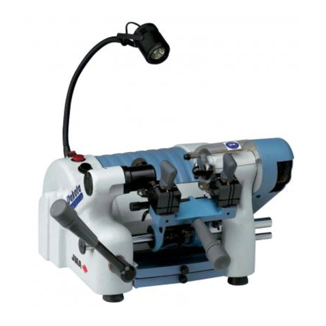
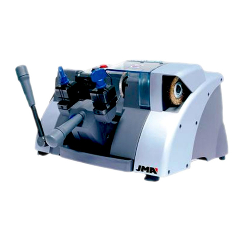
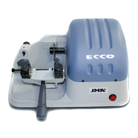
JMA SARATOGA User manual

MÁQUINA DUPLICADORA SARATOGA
Manual de instrucciones
KEY CUTTING MACHINE SARATOGA
Instruction manual
KOPIERMASCHINE SARATOGA
Anweisungshandbuch
MACHINE A TAILLER LES CLES SARATOGA
Notice d'utilisation
MÁQUINA DUPLICADORA SARATOGA
Manual de instruções

1. Presentación y aspectos generales
1.1 Generalidades 4
1.2 Transporte y embalaje 4
1.3 Etiqueta identificadora 4
2. Características de la máquina
2.1 Nomenclatura de la llave 4
2.2 Familia de llaves 4
2.3 Colocaciones opcionales 4
2.4 Datos técnicos 5
2.5 Componentes y partes funcionales 5
2.5.1 Accesorios 5
2.5.2 Circuito eléctrico 5
3. Duplicado de llaves “Bloque A”
3.1 Mordaza 4 lados 5
3.2 Control y reglaje lateral “Bloque A” 5
3.3 Control y reglaje de la profundidad 5
De corte del “Bloque A”
3.4 Operación de duplicado de la llave 6
3.4.1 Duplicado de la llave con paletón 6
estrecho. Lado 2 de la mordaza
3.4.2 Duplicado de la llave sin tope 6
3.4.3 Duplicado de la llave cruciforme 6
Lado 1 de la mordaza
4. Duplicado De Llaves “Bloque B”
4.1 Mordaza de tres lados 6
4.2 Control y reglaje lateral “Bloque B” 6
4.3 Control y reglaje de la profundidad 6
De corte del “Bloque B"
4.4 Operación de duplicado de la llave 7
4.4.1 Operación de duplicado de la 7
llave gorja
4.4.2 Duplicado de la llave frontal 7
4.4.3 Duplicado de la llave FO-4P 7
4.4.4 Duplicado de la llave gorja mediante 7
tope punta
4.4.5 Duplicado de la llave FO-6P 7
4.4.6 Duplicado de la llave “ABLOY” 8
4.4.7 Duplicado de la llave con el carro de 8
hacer REGATAS
5. Función De La Excéntrica
6. Mantenimiento Y Seguridad
6.1 Cambio de fresas 8
6.1.1 Fresa del “Bloque A” 8
6.1.2 Fresa del “Bloque B” 8
6.2 Cambio de cepillo 8
6.3 Recomendaciones de seguridad 8
1. Presentation and general aspects
1.1 General 9
1.2 Transport and packaging 9
1.3 Identifying label 9
2. Characteristics of the machine
2.1 Key nomenclature 9
2.2 Key family 9
2.3 Optional fittings 9
2.4 Technical details 10
2.5 Components and functional parts 10
2.5.1 Accessories 10
2.5.2 Electrical circuit 10
Indice / Index / Inhaltsverzeichnis / Indice / Index
4
4-5
5-6
6-8
8
8
9
9-10
3. Key copying “Block A”
3.1 4 sided clamp 10
3.2 Control and lateral adjustment of “Block A” 10
3.3 Control and cutting depth adjustment 10
of “Block A”
3.4 Key copying operation 11
3.4.1 Copying keys with narrow blades 11
side 2 of the clamp
3.4.2 Copying keys without stops 11
3.4.3 Copying cruciform keys. side 1 of 11
the clamp
4. Key Copying “BLOCK B”
4.1 3 sided clamp 11
4.2 Control and lateral adjustment of “Block B” 11
4.3 Control and cutting depth adjustment of 11
“Block B”
4.4 Key copying operation 12
4.4.1 Copying lever tumbler keys
4.4.2 Copying frontal keys 12
4.4.3 Copying fo-4p keys 12
4.4.4 Copying lever tumbler keys by means 12
of tip stop
4.4.5 Copying fo-6p keys 12
4.4.6 Copying “abloy” keys 13
4.4.7 Copying keys with the grooving 13
carriage
5. Operating The Cam
6. Maintenance And Safety
6.1 Changing milling tools 13
6.1.1 “Block A” milling tool 13
6.1.2 “Block B” milling tool 13
6.2 Changing the brush 13
6.3 Safety recommendations 13
1. Aufmachung Und Allgemeine Aspekte
1.1 Allgemeines 14
1.2 Transport Und Verpackung 14
1.3 Typenschild 14
2. Merkmale Der Maschine
2.1 Nomenklatur Des Schlüssels 14
2.2 Schlüsselformen 14
2.3 Optionale Aufnahmen 14
2.4 Technische Daten 15
2.5 Komponenten Und Funktionsteile 15
2.5.1 Zubehör 15
2.5.2 Schaltkreis 15
3. Kopieren Von Schlüsseln “Block A”
3.1 4-seitige Spannbacke 15
3.2 Seitliche Steuerung Und Regulierung “Block A” 15
3.3 Steuerung Und Regulierung Der Frästiefe “Block A”
3.4 Schlüsselkopiervorgang 16
3.4.1 Kopieren von Schlüsseln mit schmalem
Bart Seite 2 der Spannbacke
(Vorhängeschlösser/ Briefkästen)
3.4.2 Kopieren von Schlüsseln ohne Anschlag 16
3.4.3 Kopieren von Kreuzbartschlüsseln
Seite 1 der Spannbacke
4. Kopieren Von Schlüsseln “Block B”
4.1 3-seitige Spannbacke 16
4.2 Seitliche Steuerung Und Regulierung “Block B” 16
10-11
11-13
13
13
14
14-15
15-16
16-18

4.3 Steuerung Und Regulierung Der Frästiefe 16
“Block B”
4.4 SCHLÜSSELKOPIERVORGANG 17
4.4.1 Kopiervorgang für Rundschlüssel 17
4.4.2 Kopieren von Schlüsseln mit Frontzahnung 17
4.4.3 Kopieren von Schlüsseln FO-4P 17
4.4.4 Kopieren von Rundschlüsseln mittels 17
Spitzenanschlag
4.4.5 Kopieren von Schlüsseln FO-6P 17
4.4.6 Kopieren von “ABLOY”-Schlüsseln 18
4.4.7 Kopieren von Schlüsseln mit dem 18
NUTSCHLITTEN
5. Exzenterfunktion
6. Wartung Und Sicherheitshinweise
6.1 Fräsenwechsel 18
6.1.1 Fräse “Block A” 18
6.1.2 Fräse “Block B” 18
6.2 Bürtsenwechsel 18
6.3 Sicherheitshinweise 18
18
1. Présentation et aspects généraux
1.1 Généralités 19
1.2 Transport et emballage 19
1.3 Plaque d’identification 19
2. Caractéristiques de la machine
2.1 Nomenclature de la clé 19
2.2 Famille de clés 19
2.3 Emplacements en option 19
2.4 Données techniques 20
2.5 Composants et parties fonctionnelles 20
2.5.1 Accessoires 20
2.5.2 Circuit électrique 20
3. Reproduction De Clés “Bloc A”
3.1 Étau 4 faces 20
3.2 Contrôle et réglage latéral “Bloc A” 20
3.3 Contrôle et réglage de la profondeur 20
de coupe du “Bloc A”
3.4 Reproduction de la clé 21
3.4.1 Reproduction d’une clé à panneton 21
étroit. Face 2 de l’étau
3.4.2 Reproduction d’une clé sans butée 21
3.4.3 Reproduction d’une clé cruciforme. 21
Face 1 de l’étau
4. Reproduction De Clés “Bloc B”
4.1 Étau 3 faces 21
4.2 Contrôle et réglage latéral “Bloc B” 21
4.3 Contrôle et réglage de la profondeur 21
de coupe du “Bloc B”
4.4 Reproduction de la clé 22
4.4.1 Reproduction d’une clé à Gorge 22
4.4.2 Reproduction d’une clé frontale 22
4.4.3 Reproduction d’une clé FO-4P 22
4.4.4 Reproduction d’une clé à Gorge 22
Par butée à la pointe
4.4.5 Reproduction d’une clé FO-6P 22
4.4.6 Reproduction d’une clé “ABLOY” 23
4.4.7 Reproduction d’une clé avec le 23
chariot à rainurer
19
19-20
20-21
21-23
23
23
5. Fonction de l’excentrique
6. Maintenance et sécurité
6.1 Remplacement des fraises 23
6.1.1 Fraise du “Bloc A” 23
6.1.2 Fraise du “Bloc B” 23
6.2 Remplacement de la brosse 23
6.3 Recommandations de sécurité 23
1. Apresentação e aspectos gerais
1.1 Geralidades 24
1.2 Transporte e embalagem 24
1.3 Etiqueta de identificação 24
2. Características da máquina
2.1 Nomenclatura da chave 24
2.2 Familia de chaves 24
2.3 Colocações opcionais 24
2.4 Dados técnicos 25
2.5 Componentes e partes funcionais 25
2.5.1 Acessórios 25
2.5.2 Circuito eléctrico 25
3. Duplicação de chaves “Bloco A”
3.1 Grampo 4 lados 25
3.2 Controle e regulação lateral “Bloco A” 25
3.3 Controle e regulação da profundidade 25
de corte do “Bloco A”
3.4 Operação de duplicação da chave 26
3.4.1 Duplicação da chave com palhetão 26
estreito. Lado 2 do grampo.
3.4.2 Duplicação da chave sem tope. 26
3.4.3 Duplicação da chave cruciforme. 26
Lado 1 do grampo
4. Duplicação de chaves “Bloco B”
4.1 Grampo de três lados 26
4.2 Controle e regulação lateral “Bloco B” 26
4.3 Controle e regulação da profundidade 26
de corte do “Bloco B”
4.4 Operação de duplicação da chave 27
4.4.1 Operação de duplicação da chave 27
gorja
4.4.2 Duplicação da chave frontal 27
4.4.3 Duplicação da chave FO-4P 27
4.4.4 Duplicação da chave gorja mediante 27
tope ponta
4.4.5 Duplicação da chave FO-6P 27
4.4.6Duplicação da chave “ABLOY” 28
4.4.7 Duplicação da chave com o carro 28
de fazer regatas
5. Função Da Excêntrica
6. Manutenção e segurança
6.1 Permuta de fresas 28
6.1.1 Fresa do “Bloco A” 28
6.1.2 Fresa do “Bloco B” 28
6.2 Permuta de escova 28
6.3 Recomendações de segurança 28
24
24-25
25-26
26-28
28
28
18

La máquina SARATOGA es una duplicadora semi-automá-
tica de gran robustez y precisa. Preparada para el dupli-
cado de llaves planas de cerraduras a cilindro, vehículos,
llaves cruciformes (en cruz) y especiales.
A su vez, esta diseñada para el duplicado de llaves de
gorja de un paletón y de doble paletón, frontales y espe-
ciales. Sistema reversible de doble mordaza, a tres posicio-
nes. Las mordazas presentan dos guías especiales, para su
exacto centrado y con un índice copiador con regulación
micrométrica.
La máquina SARATOGA consta de dos partes, una llamada
“Bloque A”, y otra de nombre “Bloque B”.
Características
de la máquina
Cabeza
Cuello
Tope superior
Tope inferior
Paletón
Dentado
Dorso
Punta
Caña
Ver figura 2
Nomenclatura de la llave
2.1
Para la consecución de un servicio más completo por parte de
esta máquina duplicadora, se han habilitado tres colocaciones
opcionales que nos permitirán una mejora en sus prestaciones.
COLOCACIÓN RG
Ha sido estudiada para la preparación de la regata (estría) de
las llaves gorja.
COLOCACIÓN FT-COD
Nos permite el duplicado, mediante código, de la llave FORD TIBBE.
COLOCACIÓN ABL
Realizaremos con ella el duplicado de las llaves tipo ABLOY.
Estas colocaciones no se incluyen en el precio de la máquina,
siendo estas opcionales de compra.
Colocaciones opcionales
2.3
2
La máquina SARATOGA duplica los siguientes tipos de llaves:
Llaves a copiar en el “Bloque A”:
Llaves planas.
Llaves de vehículos.
Llaves cruciformes.
Llaves a copiar en el “Bloque B”:
Llaves de gorja de un paletón y de doble paletón.
Llaves frontales.
Llaves especiales.
Ver figura 3
Familia de llaves
2.2
y aspectos generales
1
4
Español
Generalidades
Presentación
1.1
La máquina duplicadora SARATOGA ha sido diseñada
teniendo en cuenta las normas de seguridad vigentes
en la C.E.E.
La seguridad del personal involucrado en el manejo
de este tipo de máquinas solo se consigue con un pro-
grama bien diseñado en seguridad personal, como la
implantación de un programa de mantenimiento y el
seguimiento de los consejos recomendados así como el
cumplimiento de las normas de seguridad que contem-
pla este manual.
Aunque la instalación de la máquina no presenta nin-
guna dificultad, es preferible que no intente instalar,
ajustar o manipular la misma sin leer primeramente
este manual.
La máquina sale de nuestra fabrica lista para el uso y
solo necesita operaciones de calibrado para los útiles
que se van a utilizar:
La máquina se presenta en el interior de un embalaje
de las dimensiones siguientes:
Ancho = 770 mm, larga = 580 mm, alto = 410mm.
Peso máquina más embalaje = 50 Kg. de peso.
Cuando desembale la máquina, inspeccione cuidado-
samente por si hubiese sufrido algún daño en el trans-
porte. Si encuentra alguna anomalía, avise inmediata-
mente al transportista y no haga nada con la máquina
hasta que el agente del transportista haya realizado la
inspección correspondiente.
La máquina duplicadora SARATOGA está provista de la
etiqueta identificadora, con especificación del numero
de serie, nombre y dirección del fabricante, marca CE y
año de fabricación. Ver figura 1
Etiqueta identificadora
1.3
Transporte y embalaje
1.2
1
2
3
4
5
6
7
8
9

5
Español
Motor : Monofásico 200 V., 50 Hz, 0.18 Kw, 1500 rpm,
1.6 Amp.
Fresa "Bloque A" : Acero extra rápido Ø80 x 16 x 5 mm.
Fresa "Bloque B" : Acero extra rápido Ø80 x 16 x 1,4 mm
(tres cortes).
Velocidad : 530 RPM.
Mordaza "Bloque A" : De cuatro posiciones.
Mordaza "Bloque B" : De tres posiciones.
Desplazamiento : Con eje deslizante y giratorio.
Alumbrado : Lámpara alógena.
Dimensiones : Ancho = 590 mm, Profundidad = 470 mm y
Alto = 260 mm.
Peso : 50 Kg.
Datos técnicos
2.4
Llave fija de 18.
Chapa de reglaje de la profundidad de corte.
Calzos para la regulacion tope punta.
Calzo con rebaje para el duplicado de la llave en cruz.
Varillas de reglaje de la profundidad de corte bloque “B”.
Piezas de reglaje lateral bloque “B”.
Juego de llaves allen (2.5, 3, 4, 5, 6).
Varilla para el cambio de la fresa (ø7x140).
1
2
3
4
5
6
7
8
Componentes y partes funcionales
2.5
2.5.1 Accesorios Ver Figura 4
2.5.2 Circuito eléctrico Ver Figura 5
Los componentes principales del circuito eléctrico y
electrónicos son los siguientes:
1
2
3
4
5
6
7
8
9
10
11
Toma de corriente 220v. 50Hz.
Regleta de conexiones.
Transformador para lámpara 220v. – 12v.
Interruptor lampara.
Lámpara alógena.
Interruptor general.
Piloto.
Microinterruptor bloque “A”.
Interruptor bloque “B”.
Condensador.
Motor.
Rele seguridad.
Llaves “Bloque A”
Mordaza 4 lados
3.1
La mordaza está diseñada para sujetar una familia de
distintas llaves en cada lado. En la figura se indican las
posibilidades de duplicado en cada lado de la mordaza.
a) El duplicado de la llave con apoyo en el dorso:
Lado 1: Llaves con paletón normal.
Lado 2: Llaves con paletón estrecho.
b) El duplicado mediante el amarre de la llave por la
guía(perfil). Lado 3 y Lado 4. Ver Figura 6
c) El duplicado mediante el amarre de la llave por la guía (tipo
NEIMAN). Ver Figura 7
Control y reglaje lateral “Bloque A”
3.2
Colocar las dos llaves de reglaje (1) en las mordazas, realizando
tope con la cabeza de la llave de reglaje sobre el tope interior
del lado 1 o 2 de la mordaza.
Seguidamente apretar las mordazas.
Acercar las mordazas con las llaves de reglaje (1) hacia el índice
copiador (I) y la fresa (F), de forma que las llaves de reglaje es-
tén en posición correcta con el índice copiador y la fresa. Esto
se consigue presionando el botón (P) y acercando suavemente
el carro sobre el índice copiador (I) y la fresa (F).
En el caso de no coincidir debidamente las muescas de las llaves
de reglaje con el índice copiador y con la fresa, actuar de la
siguiente manera:
Aflojar los tornillos (T) del soporte, e ir golpeando en el lateral
del bloque para que el soporte del índice copiador se mueva a
derecha o izquierda de forma que el mismo coincida sobre la
muesca de la llave de reglaje correspondiente.
La distancia queda perfectamente regulada, coincidiendo el
índice copiador y la fresa en los respectivos rebajes de las llaves
de reglaje. Seguidamente, apretar, bloqueándolos, los tornillos
(T) del soporte. Ver Figura 8
Con el cable de alimentacion de la maquina desconectado de la
corriente electrica.
Colocar las dos llaves de reglaje (1) en las mordazas, realizando
tope con la cabeza de la llave de reglaje sobre el tope interior del
lado 1 o 2 de la mordaza.
Acercar las mordazas con las llaves de reglaje (1) hacia el índice
copiador (I) y la fresa (F), de forma que las llaves de reglaje se
apoyen sobre el índice copiador y la fresa. El desbloqueo del carro
de la máquina se consigue presionando el botón (P).
Girar la fresa con la mano. Si la fresa roza ligeramente las llaves de
reglaje, la máquina está debidamente regulada.
Si al girar la fresa, ésta lo hace libremente; sin rozar, nos indica
que la fresa está retrasada con respecto al palpador y el fresado es
insuficiente. Por el contrario, si la fresa queda bloqueada en la llave
de reglaje, nos muestra que la fresa está adelantada con respecto al
palpador y el fresado es excesivo.
De producirse alguna de estas dos incidencias, proceder de la
siguiente forma:
Soltar el prisionero (L) que bloquea el índice copiador (I) y girar el
tornillo micrométrico (H).
Adelantar o retrasar el índice copiador, hasta que la fresa gire y
roce muy ligeramente la llave de reglaje. A continuación, apretar
el prisionero (L) del índice copiador y la máquina queda en per-
fecto estado de funcionamiento.
Ver Figura 9
Control y reglaje de la profundidad de
corte del “Bloque A”
3.3
Duplicado de
Duplicado de
3
12

6
Español
Introducir la llave original en la mordaza izquierda , man-
teniéndola a una distancia de 2 a 3 mm de separación del
borde de la mordaza.
Apretar la mordaza, manteniendo el dorso de la llave debi-
damente apoyado sobre la base de la mordaza.
Introducir la llave en bruto a duplicar en la mordaza dere-
cha y antes de apretar la mordaza elevar el calibre (C) y
alinear las dos llaves, poniendo atención en que los dos
índices del calibre se apoyen firmemente en los topes supe-
riores de ambas llaves. Por último, apretar las mordazas.
Tanto la llave original como la llave en bruto a duplicar,
deberán introducirse por la parte izquierda de las respec-
tivas mordazas.
Poner en marcha la máquina y sosteniendo el carro por
medio de la manilla (M), acercar las llaves hacia el índice
copiador (I) y la fresa (F), presionando el botón (P). El cali-
bre (C) se retira automáticamente al avanzar el carro hacia
el índice copiador y la fresa.
Recordamos que se a de trabajar de izquierda a derecha.
Apoyar la llave original contra el índice copiador y comen-
zar a trabajar, desplazando el carro de derecha a izquierda,
utilizando el brazo (B), procurando que la presión que se
haga sobre el índice copiador sea la que exija el muelle
incorporado en el eje del carro.
Terminado el duplicado de la llave, volver el carro a su
posición inicial. A continuación, retirar las llaves, aflojando
las mordazas.
Si el duplicado de la llave ha producido algunas rebabas en
la llave duplicada, estas se eliminarán utilizando el cepillo,
que para este fin se ha dotado a la máquina. Ver Figura 10
Operación de duplicado de la llave
3.4
3.4.1 Duplicado de la llave con paletón estrecho
Lado 2 de la mordaza (candados/buzones)
Para el duplicado de este tipo de llave, y con el fin de que la
fresa alcance el máximo de profundidad en el corte se va utilizar
el lado 2 de la mordaza que nos permite una profundización
mayor a la hora de duplicar.
3.4.2 Duplicado de la llave sin tope
Introducir los dos calzos (2) en las ranuras verticales (R)
de cada mordaza, en función de la longitud de la llave a
duplicar.
Apoyar las puntas de las llaves contra los calzos (2). Las llaves
quedan así regladas. Después apretar las mordazas y antes
de iniciar el duplicado de la llave, se aconseja retirar los
calzos.
Ver Figura 11
3.4.3 Duplicado de la llave cruciforme
Lado 1 de la mordaza
Este tipo de llave debe de ser introducido en las mordazas de
izquierda a derecha. Colocar los calzos (5) con la abertura o rebaje
hacia arriba, en una u otra ranura (R), según la largura de la llave a
duplicar.
El dentado de la llave se realiza en tres operaciones, girando y blo-
queando cada vez el tope de la llave sobre el calzo (5). Ver Figura 12
Duplicado de
llaves “Bloque B”:
4
Mordaza 3 lados
4.1
La mordaza está diseñada para sujetar una familia de dis-
tintas llaves en cada lado. Vamos a ver los diferentes lados:
Lado 1:
Lado para duplicar llaves de gorja de un paletón o de
doble paletón.
Lado 2:
Duplicado de llaves frontales.
Lado 3:
Duplicado de la llave especial FO-4P, en la mordaza reside una
ranura a 45o que permite la duplicación de esta llave especial.
Para más detalle pasar a los capítulos de duplicación de llaves.
Control y reglaje lateral “Bloque B”
4.2
Colocar las dos piezas de reglaje (6)
Acercar las mordazas hacia el índice copiador (I) y la fresa (F),
de forma que las piezas de reglaje se ajusten sobre el índice
copiador y la fresa. El desbloqueo del carro de la máquina se
consigue aflojando la manilla(B).
En el caso de no coincidir las piezas de reglaje con la fresa y el
índice copiador, actuar de la siguiente manera:
Aflojar los dos tornillos (T) del soporte y mediante una peque-
ña maza de plástico, dando ligeros golpes a derecha o izquier-
da de forma que el mismo coincida con la pieza de reglaje.
La distancia queda perfectamente regulada, coincidiendo el
índice copiador y la fresa con las respectivas piezas de reglaje.
Seguidamente, apretar, bloqueándolos, los tornillos (T) del so-
porte. Ver Figura 13
4.3 Control y reglaje de la profundidad de
corte del “Bloque B”
Colocar las dos varillas de reglaje (7) en las mordazas, según
indica el diseño.
Acercar las mordazas con las varillas de reglaje (7) hacia el índi-
ce copiador (I) y la fresa (F), de forma que las varillas de reglaje
se apoyen sobre el índice copiador y la fresa. El desbloqueo
del carro de la máquina se consigue aflojando la manilla (B).
Girar la fresa con la mano. Si la fresa roza ligeramente las
varillas de reglaje, la máquina está debidamente regulada.
Si al girar la fresa, ésta lo hace libremente; sin rozar, nos indica
que no corta con la suficiente profundidad. Por el contrario, si
la fresa queda bloqueada en la varilla de reglaje, nos muestra
que el corte es demasiado profundo.
De producirse alguna de estas dos incidencias, proceder de la
siguiente forma:
Soltar el tornillo prisionero (L) que bloquea el índice copiador
(I) y girar el tornillo micrométrico (H).
Adelantar o retrasar el índice copiador, hasta que la fresa gire
y roce muy ligeramente la varilla de reglaje. A continuación,
apretar el tornillo (L) del índice copiador y la máquina queda
en perfecto estado de funcionamiento. Ver Figura 14

7
Español
Operación de duplicado de la llave
4.4
4.4.1 Operación de duplicado de la llave gorja
Introducir las llaves en las mordazas, teniendo cuidado de que el
paletón de la llave apoye sobre el tope interior de la mordaza.
Poner la máquina en marcha y sosteniendo el carro por medio
de la manilla (M), acercar las llaves hacia el índice copiador (I) y
la fresa (F).
Recomendamos que se ha de trabajar pausadamente, sin forzar
la fresa. El punto redondo se consigue, girando el carro porta-
mordazas con la manilla (N). El recorrido del punto redondo se
limita con el tope (P).
Si en el duplicado se han producido algunas rebabas en la llave
duplicada, éstas se eliminarán utilizando el cepillo, que para este
fin se ha dotado a la máquina.
La entrada de la fresa conviene hacerlo con la palanca (N) y
entrar en la llave hasta el fondo.
Ver Figura 15
4.4.2 Duplicado de la llave frontal
Introducir las llaves en las mordazas, teniendo cuidado de que el
paletón de la llave apoye sobre el tope frontal de la mordaza.
Poner la máquina en marcha y sosteniendo el carro por medio
de la manilla (M), acercar las llaves hacia el índice copiador (I) y
la fresa (F).
Recomendamos que se ha de trabajar pausadamente, sin forzar
la fresa. La perpendicularidad de corte se consigue orientando
el carro con la manilla (N).
Si en el duplicado se han producido algunas rebabas en la llave
duplicada, éstas se eliminarán utilizando el cepillo, que para este
fin se ha dotado a la máquina.
La entrada de la fresa conviene hacerlo con la palanca (N) y
entrar en la llave hasta el fondo.
Ver Figura 16
4.4.3 Duplicado de la llave FO-4P
Colocamos las mordazas de gorja en la posición (C), a continua-
ción, colocamos la llave de tal manera que el paletón se asiente
sobre el rebaje de 45 o que tiene la mordaza en su lateral, así, le
damos los grados de inclinación al dentado de la llave.
Le hacemos a la llave tope de punta, fresa-palpador y procede-
mos al dentado de la misma.
Importante: Antes de colocar las llaves en la mordaza verificar la
posición de las mismas. Las llaves salen de fábrica con un diente
en uno de sus paletones mecanizado.
Ver Figura 17
4.4.4 Duplicado de la llave gorja mediante tope punta
Tenemos la pieza denominada “Soporte de punta (A-B), cuya
función es la de agilizar la puesta en la mordaza de la llave
haciendo tope de punta cuando tenemos que mecanizar varias
llaves del mismo modelo.
Situando la pieza en la posición 2, colocamos la llave que vamos
a mecanizar de manera que el paletón de la llave choque con el
tope “B” de la pieza. A continuación retiramos la pieza (soporte
punta) a la posición inicial 1.
Procederemos a la colocación de la llave original y sin mover la
llave en bruto, las ajustamos de tal manera que el paletón de la
llave en bruto choque con la fresa (C) de la máquina y el paletón
de la llave original con el palpador (D).
A continuación procederemos a mecanizar esta primera llave.
Si tenemos que mecanizar una segunda llave, y sin mover la llave
original, con solo colocar el Soporte de Punta en la posición n.o 2
y haciendo que choque el paletón de ésta segunda llave a mecani-
zar con el tope “B” del “Soporte”, tenemos centradas las llaves sin
tener que hacer tope en fresa y palpador.
Ver Figura 18
4.4.5 Duplicado de la llave FO-6P
LA LECTURA DEL CÓDIGO DE LA LLAVE ORIGINAL
La llave original tiene 6 posiciones de duplicado, y para realizar
una lectura correcta de ésta, debemos coger la llave con la mano
izquierda, es decir, quedando el paletón de la llave a la derecha
de la cabeza de plástico negro, tal y como se indica en el dibujo.
Ver Figura 19
Las posiciones en el duplicado de la llave, corresponden a
combinaciones de 4 distintas alturas que ahora señalamos y
vamos a numerar:
1 2 3 4
La altura n.o1, nos indica que no se debe duplicar. La posición
n.o2 nos señala que hay un pequeño rebaje en la llave y que
cuando es algo mayor corresponde a la altura n.o3. La altura
n.o4 es el mayor de los rebajes de la llave.
Entonces cogeríamos la llave y marcaríamos las 6 posiciones, tal
y como señalamos a continuación en función de las distintas
alturas:
POSITION A B C D E F
INCLINATION 3 4 1 2 4 2
Una vez conocido el código de la llave a duplicar, se coloca la llave
en bruto en la mordaza, y colocando la pieza (L) en la posición 1, la
llave debe de quedar completamente plana tal que si acercamos
la llave a la fresa, esta debe hacer marca en el centro de la llave.
Ver Figura 20
De no ser así, se debe soltar el espárrago (H), y entonces centramos
la llave, y utilizamos la pieza (J) realizando el ajuste correcto.
La pieza (I) es la bola de código que tiene 6 letras, correspondien-
tes a las 6 posiciones.
La pieza (J) sirve para el reglaje vertical.
La pieza (K) se utiliza en el reglaje horizontal.
La pieza(L) sirve para dar las inclinaciones correctas a la llave, en
función de la posición a que corresponda.
Haremos un pequeño ejemplo con la lectura anterior:
POSITION A B C D E F
INCLINATION 3 4 1 2 4 2
Colocamos la pieza (L) en la posición superior 3, e introducimos el
palpador en la bola pieza I en la letra A y efectuamos el duplicado
correspondiente. Hacemos la misma operación con la altura 4,
introduciendo el palpador en la pieza I en la letra B y comiendo
con la fresa la altura correspondiente, y así sucesivamente hasta
las 6 posiciones.
Posteriormente haremos lo mismo con los 4 números inferiores
de la pieza (L), duplicando así, el otro lado de la misma cara de
la llave.
Para duplicar la otra cara de la llave, damos la vuelta a la misma,
y volvemos a realizar la misma operación, utilizando siempre el
mismo código, ya que la llave es simétrica, y por ello se mantiene
el mismo código.

Español
8
La función de la excéntrica es la de centrar el punto redondo
del dentado de la llave. Compensa la diferencia del diámetro
de caña de los distintos modelos de llave gorja.
En el cuerpo de la excéntrica aparecen reflejadas cinco posicio-
nes. Una primera posición, indicada con el n.o4, para las llaves
que tienen diámetro de caña de 4mm., una segunda posición,
que nos marca la pieza, pero que no aparece indicada con
ninguna numeración, para las llaves de 5mm. de diámetro de
caña, una tercera posición, indicada con el número 6, para llaves
de 6mm. de caña, una cuarta posición, cuyo paso nos indica la
pieza excéntrica pero que no aparece reflejado con ninguna
numeración, para las llaves de 6.5mm. de caña y una última
posición, para las llaves de 7mm. de caña.
Ejemplo: Si la llave que vamos a mecanizar en la máquina, es de
6mm. de diámetro de caña, la excéntrica tiene que ir colocada
en la posición n.o6.
Ver Figura 23
Cambio de fresas
6.1
4.4.6 Duplicado de la llave “ABLOY”
Colocar dos llaves en bruto, una en cada mordaza a derecha o
izquierda y mirar que toque tanto la fresa como el palpador, si
la fresa o el palpador no tocase tiene que reglarse.
Para el reglaje tienen que aflojarse los tornillos de la pieza 5-14
(que es la regla que lleva en la parte inferior) y podrá moverse
todo el útil hacia delante o atrás, hasta que la fresa y el palpa-
dor toquen las llaves.
Para el tope de punta sería una llave colocando la fresa y la otra
llave al palpador.
Ver Figura 21
4.4.7 Duplicado de la llave con el carro de hacer REGATAS
Colocar dos llaves en bruto, una en cada soporte a derecha o
izquierda y mirar que toque tanto la fresa como el palpador, si
la fresa o el palpado no tocase tiene que reglarse.
Para el reglaje tienen que aflojarse los tornillos de la pieza 5-14
(que es la regla que lleva en la parte inferior) y podrá moverse
todo el útil hacia delante o atrás, hasta que la fresa y el palpador
toquen las llaves.
Ver Figura 22
A la hora de ejecutar cualquier operación de manteni-
miento, es necesario cumplir los requisitos:
1. Nunca se debe efectuar ninguna operación con la máquina
en marcha.
2. Se debe desconectar el cable de la conexión eléctrica.
3. Se han de seguir estrictamente las indicaciones del manual.
4. Utilizar piezas originales de repuesto.
Función
de la excéntrica
5
Mantenimiento
Y seguridad
6
6.1.1 Fresa del “Bloque A”:
Quitar el tornillo del guarda fresa y el guarda del cepillo lateral.
Levantar el guarda.
Para el caso del cambio fresa: Introducir la varilla en el agujero
del eje (A) y soltar la tuerca (K) –rosca izquierda- en sentido de
giro horario, utilizando para ello una llave fija.
Para colocación de la nueva fresa, realizar la operación inversa.
6.1.2 Fresa del “Bloque B”:
Retirar la guarda que cubre la fresa (F). Introducir la varilla (6)
en el agujero del husillo (A) y soltar la tuerca (K) de la fresa que
deseamos cambiar con la llave fija.
Una vez retirada la fresa a cambiar colocar la nueva realizando
la operación inversa.
Ver Figura 24
Cambio de cepillo
6.2
Para cambiar el cepillo quitar la tapa (P) soltando los 4 tornillos
(R) que la sujetan. Seguidamente introducir la varilla (9) en el
agujero del eje porta fresas (A) y soltar el tornillo (T) de sujeción
del cepillo (C) utilizando la llave ALLEN correspondiente.
Después de extraer el cepillo (C) colocar el nuevo actuando de
forma inversa.
Ver Figura 25
Recomendaciones de seguridad
6.3
1. No intente arrancar o manipular la máquina hasta que todos
los temas de seguridad, instrucciones para la instalación, guía
del operario y procedimientos de mantenimiento, hayan sido
cumplimentados y entendidos.
2. Desconecte siempre el suministro eléctrico, antes de realizar
cualquier trabajo de limpieza o mantenimiento.
3. Mantener la fresa limpia y libre de virutas.
4. Mantenga siempre limpia la máquina así como su entorno.
5. Se tiene que trabajar con las manos secas.
6. Se tiene que usar gafas de protección, aún que la máquina
tenga protección.
7. Asegúrese que la máquina tenga toma a tierra.

9
English
See figure 2
General
and general aspects
1
1.1
The SARATOGA has been designed in accordance with
the safety regulations in force in the EU.
The safety of personnel responsible for operating
this kind of machines can only be achieved with a
well-designed personal safety programme with, the
implementation of a maintenance programme and by
following our recommendations, as well by complying
with the safety standards included in this manual.
Although the machine is not difficult to install, it is
better not to try to install, adjust or handle this without
first reading this manual.
The machine leaves the factory ready for use and only
requires calibration of the tools that are going to be
used:
The machine is shipped inside a package with the follo-
wing dimensions:
Width 770 mm, length= 580 mm, height = 410mm
Weight of machine plus packaging = 50 kg.
On unpacking the machine, examine it closely for
any damage it might have suffered during transport.
Should you observe any anomaly, get in touch with
the forwarding agent immediately and do not do
anything with the machine until the latter has carried
out the corresponding inspection.
The SARATOGA key-copying machine has been pro-
vided with an identifying label, specifying the serial
number, name and address of the manufacturer, CE
mark and year of manufacture. See figure 1
Identifying label
1.3
Transport and Packaging
1.2
Presentation
The SARATOGA is a semiautomatic, sturdy and accurate
copying machine, designed for copying flat cylinder lock
keys, vehicle, cruciform and special keys.
In turn, it is designed for duplicating lever tumbler keys
with one blade and twin blades, frontal and special keys.
Double, 3-position clamp reversible system. The clamps
have special guides for precise centring and with an adjus-
table copying index.
The SARATOGA machine consists of two parts: one is
called “Block A”, and the other “Block B”.
Characteristics
of the machine
Head
Neck
Upper stop
Lower stop
Blade
Serrations
Back
Tip
Shaft
Key nomenclature
2.1
To achieve a more complete service from this copying machine,
3 optional fittings have been provided to allow us to improve
its features.
RG FITTING
This has been designed in order to prepare the groove in lever
tumbler keys.
FT-COD FITTING
Allows us to copy the FORD TIBBE key by means of codes.
ABL FITTING
Use this to duplicate ABLOY type keys.
These fittings are not included in the price of the machine, and
are optional extras.
2.3 Optional fittings
2.3
2
The SARATOGA machine copies the following types of keys:
Keys to be copied in “Block A”:
Flat keys
Vehicle keys.
Cruciform keys.
Keys to be copied in “Block B”:
Lever tumbler keys with one blade and twin blades.
Frontal keys.
Special keys.
See figure 3
Key family
2.2
1
2
3
4
5
6
7
8
9

The main technical details are set out below:
Motor: Single phase 220V, 50Hz, 0.18Kw,1500 rpm, 1.6 Amp.
“Block A” Milling tool: Extra high-speed steel ø80 x 16 x5 mm.
“Block B” Milling tool: Extra high-speed steel ø80 x 16 x 1.4 mm
(three cuts).
Speed: 530 rpm.
“Block A” Clamp: Four positions.
“Block B” Clamp: Three positions.
Displacement: With sliding and turning shaft.
Lighting: Halogen lamp.
Dimensions: Width = 590 mm, Depth = 470 mm, Height = 260 mm.
Weight: 50 Kg.
Technical details
2.4
Wrench of 18.
Cutting-depth adjustment plate.
Shims for adjusting the tip stop.
Shim with recess for duplicating cruciform keys.
Cutting-depth adjustment plate, block “B”.
Sided adjustment pieces, block “B”.
Set of Allen keys (2.5, 3, 4, 5, 6).
Rod for changing milling tool (ø7x140).
1
2
3
4
5
6
7
8
Components and functional parts
2.5
2.5.1 Accessories See figure 4
2.5.2 Electrical circuit See figure 5
The main components of electrical and electronic cir-
cuit are as follows:
1
2
3
4
5
6
7
8
9
10
11
220V current intake. 50Hz.
Connector strip
Transformer for 220V lamp. – 12v.
Lamp switch.
Halogen lamp.
General switch.
Pilot lamp.
Block “A” microswitch.
Block “B” microswitch.
Condenser.
Motor.
Security relay.
with “Block A”
4 sided clamp
3.1
The clamp is designed to secure a family of different
keys on each side. The figure shows the possibilities for
copying on each side of the clamp.
a) Copying keys with a support on the back:
Side 1: Keys with normal blade.
Side 2: Keys with narrow blade.
b) Copying by securing the key with the guide (profile).
Side 3 and Side 4. See figure 6
c) Copying by securing the key with the guide (NEIMAN type)
See figure 7
Control and lateral adjustment “Block A”
3.2
Place the two adjustment keys (1) in the clamps. The head of
the adjustment key butts against the inside stop of side 1 or 2
of the clamp.
Now tighten the clamps.
Move the clamps with the adjustment keys (1) towards the co-
pying index (I) and the milling tool (F) so that the adjustment
keys are in the correct position with the copying index and the
milling tool. This can be done by pressing the button (P) and
moving the carriage gently over the copying index (I) and the
milling tool (F). See figure 2
Should the notches in the adjustment keys not coincide with the
copying index and with the milling tool, proceed as follows:
Loosen the (T) screws in the support, and knock the side of the
block so that the copying index support moves to the right or
left in order to make this coincide with the notch in the corres-
ponding adjustment key.
The distance is now perfectly adjusted and the copying index and
the milling tool coincide with the respective recesses in the adjust-
ment keys. Now, tighten to lock the screws (T) in the support.
See figure 8
Disconnect the machine’s power cable from mains electricity.
Place the two adjustment keys (1) in the clamps. The head of the
adjustment key butts against the inside stop of side 1 or 2 of the
clamp.
Move the clamps with the adjustment keys (1) towards the copying
index (I) and the milling tool (F) so that the adjustment keys rest
against the copying index and the milling tool. The machine carria-
ge is released by pressing the button (P).
Turn the milling tool with your hand. When the milling tool rubs slig-
htly against the adjustment keys, the machine is correctly adjusted.
If the milling tool turns freely, without rubbing, this indicates that
the milling tool is moving behind the tracer and is not cutting
sufficiently. On the other hand, if the milling tool is locked in the
adjustment key, the shows that the milling tool is moving ahead
of the tracer and is cutting excessively. If one of these two incidents
occurs, proceed as follows:
Loosen the set screw (J) that locks the copying index (I) and turning
the micrometric screw (H). See figure No. 3.
Bring the copying index forward or back until the milling tool turns
and rubs the adjustment key very slightly. Next, tighten the set screw
(J) of the copying index. The machine is now ready to operate.
See figure 9
Control and adjustment of the cutting
depth of “Block A”
3.3
Duplicado de
Copying keys
3
English
10
12

11
Insert the original key in the left-hand clamp, keeping a
distance of from 2 to 3 mm between it and the edge of the
clamp. See figure 4
Tighten the clamp, keeping the back of the key correctly
supported on the base of the clamp.
Insert the uncut key in the right-hand clamp and before
taking the clamp, lift the gauge (C) and align the two keys,
making sure that the two calibre indices rest firmly on the
upper stops of both keys. Lastly, tighten the clamps.
Both the original key and the uncut key for copying must
be inserted from the left of the respective clamps.
Start the machine and by holding the carriage by means
of the handle (M), move the keys towards the copying
index (I) and the milling tool (F), by pressing the button
(P). Gauge (C) withdraws automatically when the carriage
moves towards the copying index and the milling tool.
Remember that the machine works from left to right.
Rest the original key against the copying index and begin
to work, moving the carriage from right to left, using
the arm (B). Make sure that the pressure exerted on the
copying index is the one required by the spring built into
the carriage shaft.
When the key has been copied, returned the carriage to
the original position. Now, withdraw the keys by releasing
the clamps.
If, when copying, burrs are left on the copied key, these
may be eliminated with the brush provided for this purpo-
se. See figure 10
Key copying operation
3.4
3.4.1 Copying keys with narrow blades. Side 2 of
the clamp.(padlocks/letterboxes)
For copying this kind of key, and so that the milling tool reaches
the maximum cutting depth, use side 2 of the clamp as this allo-
ws you to cut more deeply when copying.
3.4.2 Copying keys without stops
Insert the two shims (2) (see figure no. 6) in the vertical
grooves (R) of each clamp, in accordance with the length of
the key to be copied.
Rest the tips of the keys against the shims (2). The keys
are adjusted in this way. Now, tighten the clamps. Before
starting to copy the key, it is advisable to remove the shims.
See figure 11
3.4.3 Copying the cruciform key. Side 1 of the clamp
This type of key must be inserted in the clamps from left to right.
Place the shims (5) (see figure no. 7) with the opening or recess
downwards, in one or other groove (R), according to the length
of the key to be copied.
The serrations of the key are cut in three positions, by turning and
locking the stop of the key on the shim on each occasion (5).
See figure
12
The copying
keys “Block B”:
4
3 sided clamp
4.1
The clamp is designed to secure a family of different keys
on each side. Let’s take a look at the different sides:
Side 1:
Side for copying lever tumbler keys with one blade or
twin blade.
Side 2:
Copying frontal keys.
Side 3:
Copying the special key FO-4P. In the clamp there is a 45º
groove that allows this special key to be copied.
For more details, see the chapters on key copying.
Control and lateral adjustment “Block B”
4.2
Place the two adjustment pieces (6).
Move the clamps towards the copying index (I) and the milling
tool (F) so that the adjustment keys rest on the copying index
and the milling tool. The machine carriage is released by loose-
ning the handle (B).
Should the adjustment keys not coincide with the copying in-
dex and with the milling tool, proceed as follows:
Loosen the two screws (T) of the support and, with a small plas-
tic hammer, tap this slightly to the right or left so that it coinci-
des with the adjustment key. See figure No. 2.
Now, the distance is perfectly adjusted and the copying index
and the milling tool coincide with the respective adjustment
pieces. Now, tighten to lock the support screws (T).
See figure 13
4.3 Control and adjustment of the cutting
depth of “Block B”
Place the two adjustment bars (7) on the clamps, as indicated
in the design.
Move the clamps with the adjustment bars (7) towards the co-
pying index (I) and the milling tool (F) so that the adjustment
rods rest against the copying index and the milling tool. The
machine carriage is released by loosening the handle (B).
Turn the milling tool with your hand. If the milling tool rubs
against the adjustment rods slightly, the machine is correctly
adjusted.
If the milling tool turns freely, without rubbing, this indicates
that it does not cut at a sufficient depth. On the other hand, if
the milling tool jams in the adjustment rod, this shows that the
cut is too deep.
If one of these two incidents occurs, proceed as follows:
Release the set screw (L) that locks the copying index (I) and
turn the micrometric screw (H). See figure no. 3.
Bring the copying index forward or backward until the milling
tool turns and rubs against the adjustment rod very slightly.
Now, tighten the screw (L) of the copying index. The machine
is now in perfect working order.
English

12
Key copying operation
4.4
4.4.1 Copying lever tumbler keys
Insert the keys in the clamps, being careful that the key blade
rests on the inside stop of the clamp, as can be seen in figure
no. 4.
Start the machine and by holding the carriage by means of the
handle (M), move the keys towards the copying index (I) and the
milling tool (F).
We recommend you to work slowly, without forcing the milling
tool. The rounded tip is copied by turning the clamp holder
carriage with the handle (N). The range of travel of the rounded
tip is restricted by means of the stop (P).
If, when copying, burrs are left on the copied key, these may be
eliminated with the brush provided for this purpose.
It is advisable to insert the milling tool with the lever (N) and to
insert this as far as it will go into the key.
See figure
15
4.4.2 Copying frontal keys
Insert the keys in the clamps, being careful that the key blade
rests on the front stop of the clamp, as can be seen in figure
no. 5.
Start the machine and by holding the carriage by means of the
handle (M), move the keys towards the copying index (I) and
the milling tool (F).
We recommend you to work slowly, without forcing the milling
tool. The perpendicular alignment of the cut is achieved by
turning the carriage with the handle (N).
If, when copying, burrs are left on the copied key, these may be
eliminated with the brush provided for this purpose.
It is advisable to insert the milling tool with the lever (N) and to
insert this as far as it will go into the key.
See figure
16
4.4.3 Copying FO-4P keys
Place the lever tumbler clamps in position (C), and then place the
key so that the blade rests on the 45° recess in the side of the
clamp. In this way you can establish the correct inclination of
the key serrations.
Use the tip stop key as the tracer-milling tool and cut the serra-
tions in the key.
NB: Before placing the keys in the clamp, check on their position.
The keys leave factory with one machined tooth in one of their
blades.
See figure
17
4.4.4 Copying lever tumbler keys with the tip stop
The function of the part called the “Tip support (A-B)” is to facili-
tate placing the key in the clamp by butting against the tip when
it is necessary to cut several keys of the same model.
Place the part in position 2, and position the key to be cut so that
the key blade butts against stop “B” of the part. Now remove
the part (tip support) to the starting position 1.
Place the original key and without moving the uncut key, adjust
these so that the blade of the uncut key butts against the milling
tool (C) of the machine and the blade of the original key (D)
butts against the tracer.
Now machine the first key.
If it is necessary to machine a second key, without moving the
original key, just by placing the Tip Support in position No. 2, and
by making the blade of a second key to be machined butt against
stop “B” of the “Support”, you can centre the keys without
having to making these butt against the milling tool and tracer.
See figure
18
4.4.5 Copying FO-6P keys
READING THE CODE OF THE ORIGINAL KEY
The original key has 6 copying positions and in order to read this
correctly, you must take the key with your left hand, in other
words, with the blade to the right of the black plastic head, as
indicated in the drawing.
See figure
19
The key copying positions correspond to combinations of four
different heights, which we indicate and number below:
1 2 3 4
Height no. 1, indicates that it must not be copied. Position no.
2 indicates that there is a small recess in the key and when it is
slightly bigger it corresponds to height no. 3. Height no. 4 is the
biggest of the key recesses.
Then take the key and mark the 6 positions, as indicated below
in accordance with the different heights:
POSITION A B C D E F
INCLINATION 3 4 1 2 4 2
Once the code of the key to be copied has been determined, the
uncut key is placed in the clamp and after placing part (L) in posi-
tion 1, the key must be completely flat so that when we present
the key to the milling tool, the latter must make a mark in the
centre of the key.
See figure
20
If this does not happen, release the stud (H), and centre the key by
using part (J) to make the correct adjustment.
Part (I) is the code ball. This has 6 letters, corresponding to the 6
positions.
Part (J) is used for the vertical adjustment.
Part (K) is used in the horizontal adjustment.
Part (L) is used for placing the key at the correct inclination in
accordance with its corresponding position.
Here is an example with the above reading:
POSITION A B C D E F
INCLINATION 3 4 1 2 4 2
Place part (L) in the upper position 3, and insert the tracer in the
ball, part I in letter A, and carry out the corresponding copying
operation. Perform the same operation with height 4, inserting
the tracer in part I in letter B and remove the corresponding
height with the milling tool. Machine the 6 positions in the same
way.
Now do the same with the 4 lower numbers of part (L), and in this
way copy the other side of the same face of the key.
In order to copy the other side of the key, turn it over and carry out
the same operation, using the same code in all cases, as the key is
symmetrical and therefore the same code is maintained.
English

13
The function of the cam is to centre the rounded tip of the key
serration. It compensates for any difference in the diameter of
the shaft of different lever tumbler the keys. See figure 1
Five positions are shown on the cam body. The first position,
indicated with no. 4, is for keys with a shaft diameter of 4 mm.
The second edition, which marks the part, put is not indicated
with any numbering, is for keys with a shaft diameter of 5 mm.
The third position, indicated with no. 6, is for 6 mm shafts. The
fourth position, the pitch of which indicates the eccentric part
but does not show any numbering, is for keys with 6.5 mm
shafts. The last position is for keys with 7 mm shafts.
Example: If the key you are going to cut in the machine has a 6
mm shaft, the cam must be placed in position no. 6.
See figure
23
Changing milling tools
6.1
4.4.6 Copying “ABLOY”keys
Place the uncut keys, one on each side of the clamp and make sure
that this touches both the milling tool and the tracer. If the clamp does
not touch the milling tool or the tracer, this will require adjustment.
In order to make the adjustment, you must loosen the screws on
part 5-14 (which is the ruler placed underneath) and the complete
tool can be moved forward or backwards, until the milling tool and
the tracer touch the keys.
For the tip stop, this would be a key placing the milling tool and the
other key placing the tracer.
See figure
21
4.4.7 Copying keys with the GROOVING carriage
Place the uncut keys, one on each side of the clamp and make
sure that it touches both the milling tool and the tracer. If the
clamp does not touch the milling tool or the tracer, this will
require adjustment.
In order to make the adjustment, you must loosen the screws
on part 5-14 (which is the ruler placed underneath) and the
complete tool can be moved forward or backwards, until the
milling tool and the tracer touch the keys.
See figure
22
When carrying out any maintenance work, it is necessary
to comply with the following requirements.
1. Never do any maintenance with the machine in operation.
2. The cable must be disconnected from the mains outlet.
3. The indications in the manual must be strictly adhered to.
4. Use original spare parts.
Operating
the cam
5
Maintenance
and safety
6
6.1.1 “Block A” Milling tool:
Remove the screw from the milling tool guard as well as the
lateral brush guard. Raise the guard.
For changing the milling tool: Insert the rod in the hole in the
team (A) and remove the screw (K) –left-hand thread-, cloc-
kwise, using a wrench for this purpose.
In order to place a new milling tool, follow the same procedure
but in the opposite order.
6.1.2 “Block B” Milling tool:
Remove the guard that covers the milling tool (F). Insert the rod
(6) in the hole in the spindle (A) and remove the nut (K) of the
milling tool you wish to change with a wrench.
Once the milling tool has been removed, place the new one
following the same procedure in the opposite order.
See figure
24
Changing brushes
6.2
In order to change the brash, remove the cover (P) by removing
the 4 screws (R) that secure this in place. Next, insert the rod (9)
in the hole in the milling tool shaft (A) and remove the screw (T)
that fastens the brash (C) using the corresponding ALLEN key.
After extracting the brush (C) fit the new one following the
same procedure in the opposite order.
Safety recommendations
6.3
1. Never try to start or handle the machine until all safety issues,
instructions for installation, operator’s guide and maintenan-
ce procedures have been complied with and understood.
2. Disconnect the machine from mains electricity whenever
cleaning or maintenance work is being done.
3. Keep the milling tool clean and free of shavings.
4. Keep the machine and its environment clean at all times.
5. Always work with dry hands.
6. Wear safety glasses even when the machine is fitted with a
safety guard.
7. Make sure that the machine is earthed.
English

und allgemeine aspekte
1
14
Deusch
Allgemeines
Aufmachung
1.1
Die Kopiermaschine SARATOGA wurde nach den gel-
tenden CEE-Sicherheitsnormen konzipiert.
Die Sicherheit des Personals, das diese Art von
Maschinen bedient, wird nur durch gut durchdach-
te Sicherheitsprogramme erzielt wie die Einführung
eines Instandhaltungsprogramms und die Befolgung
der Empfehlungen sowie die Einhaltung der in dieser
Betriebsanleitung aufgeführten Sicherheitshinweise.
Obwohl die Installation dieser Maschine einfach ist,
sollten Sie sie nicht installieren, einstellen oder bedie-
nen, ohne vorher diese Betriebsanleitung gelesen zu
haben.
Die Maschine verlässt unser Haus betriebsbereit und
muss nur bei Verwendung der Werkzeuge kalibriert
werden.
Die Maschine wird in einer Verpackung mit folgenden
Abmessungen geliefert:
Breite = 770 mm, Länge = 580 mm, Höhe = 410 mm.
Gewicht, einschließlich Verpackung = 50 kg.
Prüfen Sie die Maschine beim Auspacken sorgfältig auf
Transportschäden. Sollten Sie Beschädigungen festste-
llen, wenden Sie sich bitte umgehend an den Spediteur
und lassen Sie die Maschine unberührt, bis der zus-
tändige Vertreter der Spedition die entsprechende
Überprüfung durchgeführt hat.
Die Schlüsselkopiermaschine SARATOGA verfügt über
ein Typenschild, auf dem sich Serien-Nr., Name und
Anschrift des Herstellers, CE-Zeichen und Baujahr befin-
den. Siehe Abbildung 1
Typenschild
1.3
Transport und verpackung
1.2
Die Maschine SARATOGA ist eine halbautomatische, robus-
te und präzise Kopiermaschine. Sie dient zum Anfertigen
von Kopien von Zylinderschlüsseln, Autoschlüsseln,
Kreuzbartschlüssel und Spezialschlüssel.
Gleichzeitig ist sie zum Kopieren von Einbart- und
Doppelbartrundschlüssel, Schlüsseln mit Frontzahnung
und Spezialschlüsseln konzipiert. Auswechselbare
Spannbacken mit drei Positionen. Die Spannbacken
verfügen über zwei Spezialführungen zur genauen
Zentrierung und einen Kopierindex mit Regulierung im
Mikrometerbereich.
Die Maschine SARATOGA besteht aus zwei Teilen: dem
“Block A” und dem “Block B”.
Merkmale
der maschine
Schlüsselkopf
Schlüsselhals
Oberer Anschlag
Unterer Anschlag
Schlüsselbart
Schlüsselzahnung
Schlüsselrücken
Schlüsselspitze
Schlüsselschaft
Siehe Abbildung 2
Nomenklatur des schlüssels
2.1
Um mit dieser Kopiermaschine einen breiteren Service anbie-
ten zu können, verfügt sie über drei optionale Aufnahmen.
AUFNAHME RG
Speziell konzipiert für die Durchführung der Kehlung (Nuten)
bei Bohrmuldenschlüssen.
AUFNAHME FT-COD
Erlaubt anhand eine Codes die Kopie des Schlüssel FORD TIBBE.
AUFNAHME ABL
Mit dieser Aufnahme können ABLOY-Schlüssel kopiert werden.
Diese Aufnahmen sind nicht im normalen Lieferumfang der
Maschine enthalten und als Extras gegen Aufpreis erhältlich.
Optionale aufnahmen
2.3
2
Die SARATOGA fertigt Kopien folgender Schlüsselformen an:
Schlüsselkopien mit “Block A”:
Zylinderschlüssel.
Autoschlüssel.
Kreuzbartschlüssel.
Schlüsselkopien mit “Block B”:
Einbart- und Doppelbartrundschlüssel.
Schlüssel mit Frontzahnung.
Spezialschlüssel.
Siehe Abbildung 3
Schlüsselformen
2.2
1
2
3
4
5
6
7
8
9

Die Spannbacke ist zum Festhalten einer Schlüsselfamilie
auf jeder Seite konzipiert. In der Abbildung werden die
Kopiermöglichkeiten auf jeder Seite der Spannbacke dargestellt.
a) Kopiervorgang für Schlüssel, die am Schlüsselrücken
gestützt werden:
Seite 1: Einbartschlüssel.
Seite 2: Doppelbartschlüssel.
b) Kopiervorgang mit Einspannen des Schlüssels im
Führungsschlitten (Profil). Seite 3 und 4 Siehe Abbildung 6
c) Kopiervorgang mit Einspannen des Schlüssels im
Führungsschlitten (Typ NEIMAN). Siehe Abbildung 7
15
Deusch
Nachstehend sind die technischen Hauptmerkmale aufgeführt:
Motor: Einphasig - 220 V - 50 Hz - 0,18 kW - 1.500 U/min - 1,6 A.
Fräse “Block A”: Schnellarbeitsstahl, Ø80 x 16 x 5 mm.
Fräse “Block B”: Schnellarbeitsstahl, Ø80 x 16 x 1,4 mm.
Geschwindigkeit: 530 U/min.
Spannbacke “Block A”: Vier Positionen.
Spannbacke “Block B”: Drei Positionen.
Verfahrbewegung: Per Gleit- und Drehachse.
Beleuchtung: Halogenlampe.
Abmessungen: Breite = 590 mm, Tiefe = 470 mm, Höhe =
260 mm.
Gewicht: 50 kg.
Technische daten
2.4
18er Maulschlüssel.
Regulierblech zum Einstellen der Frästiefe.
Keile zur Regulierung des vorderen Anschlags.
Keil mit Aussparung zum Kopieren von Kreuzbartschlüsseln.
Regulierstangen zum Einstellen der Frästiefe Block “B”.
Seitliche Regulierstücke Block “B”.
Satz Inbusschlüssel (2,5; 3; 4; 5; 6).
Stange für Fräsenwechsel (Ø7x140).
1
2
3
4
5
6
7
8
Komponenten und funktionsteile
2.5
2.5.1 Zubehör Siehe Abbildung 4
2.5.2 Schaltkreis Siehe Abbildung 5
Die elektrischen und elektronischen Hauptbestandteile
des Schaltkreises sind folgende:
1
2
3
4
5
6
7
8
9
10
11
Netzanschluss 220V 50 Hz.
Klemmenleiste.
Transformator für Lampe 220V – 12V.
Schalter Lampe.
Halogenlampe.
Hauptschalter.
Kontrollleuchte.
Mikroschalter Block “A”.
Schalter Block “B”.
Kondensator.
Motor.
Sicherheit Relais.
schlüsseln “BLOCK A”:
4-seitige spannbacke
3.1
Seitliche steuerung und regulierung “Block
A”
3.2
Die beiden Stellschlüssel (1) an den Spannbacken so einstellen,
dass der Kopf des Stellschlüssels am inneren Anschlag der Seite
1 oder 2 der Spannbacke anliegt.
Danach die Spannbacken anziehen.
Die Spannbacken mit den Stellschlüsseln (1) zum Kopierindex
(I) und der Fräse (F) verfahren, so dass die Stellschlüssel in Bezug
auf den Kopierindex und die Fräse ordnungsgemäß positio-
niert sind. Hierzu muss der Knopf (P) betätigt und der Schlitten
vorsichtig über dem Kopierindex (I) und der Fräse (F) positio-
niert werden. Siehe Abb. 2.
Sollten die Kerben der Stellschlüssel nicht mit dem Kopierindex
und der Fräse fluchten, ist wie folgt vorzugehen:
Die Schrauben (T) der Halterung lösen und den Kopierindex
durch leichte Schläge auf die Seitenteile des Blocks nach links
bzw. rechts bewegen, bis er mit der Kerbe des entsprechenden
Stellschlüssels fluchtet.
Der Abstand ist korrekt eingestellt, wenn der Kopierindex und
die Fräse mit den entsprechenden Aussparungen in den Ste-
llschlüsseln fluchten. Danach sind die Schrauben (T) der zuvor
arretierten Halterung anzuziehen.
Siehe Abbildung 8
Hierzu ist die Maschine vom Stromnetz zu trennen.
Die beiden Stellschlüssel (1) an den Spannbacken so einstellen, dass
der Kopf des Stellschlüssels am inneren Anschlag der Seite 1 oder 2
der Spannbacke anliegt.
Die Spannbacken mit den Stellschlüsseln (1) zum Kopierindex
(I) und der Fräse (F) verfahren, so dass die Stellschlüssel auf dem
Kopierindex und der Fräse aufliegen. Zum Entriegeln des Schlittens
der Maschine muss der Knopf (P) betätigt werden.
Die Fräse von Hand drehen. Wenn die Fräse leichten Kontakt an den
Stellschlüsseln hat, ist die Maschine ordnungsgemäß eingestellt.
Wenn die Fräse frei gedreht werden kann und kein Kontakt bes-
teht, ist die Fräse in Bezug auf den Taster nach hinten versetzt und
die Frästiefe nicht ausreichend. Liegt die Fräse dagegen zu stark auf
dem Stellschlüssel auf, ist sie in Bezug auf den Taster nach vorne
versetzt und die Frästiefe zu hoch.
Sollte es zu einem der vorstehend genannten Vorfälle kommen, ist
wie folgt vorzugehen:
Die Klemmschraube (J) lösen, die den Kopierindex (I) verriegelt und
die Mikrometerschraube (H) drehen. Siehe Abb. 3.
Den Kopierindex nach vorne oder hinten verschieben, bis die
Fräse sich leicht drehen lässt und leicht am Stellschlüssel anliegt.
Anschließend die Klemmschraube (J) des Kopierindexes anziehen
und die Maschine ist betriebsbereit.
Siehe Abbildung 9
Steuerung und regulierung der frästiefe
“Block A”
3.3
Duplicado de
Kopieren von
3
12

16
Den Originalschlüssel mit einem Abstand zum Rand der
Spannbacke von 2 bis 3 mm in die linke Spannbacke einle-
gen. Siehe Abbildung 4
Die Spannbacke anziehen, wobei der Schlüsselrücken ordnungs-
gemäß auf der Grundfläche der Spannbacke aufliegen muss.
Den Schlüsselrohling in die rechte Spannbacke einlegen und
vordem AnziehendieLehre (C)anheben.Die beidenSchlüssel
ausrichten und darauf achten, dass beide Lehrenindexe fest
auf den oberen Anschlägen beider Schlüssel aufliegen.
Anschließend die Spannbacken anziehen.
Sowohl der Originalschlüssel als auch der Schlüsselrohling
müssen von links in die jeweilige Spannbacke eingelegt
werden.
Die Maschine einschalten, den Schlitten mit dem Handgriff
(M) festhalten und durch Betätigen des Knopfes (P) die
Schlüssel an den Kopierindex (I) und die Fräse (F) heranf-
ahren. Die Lehre (C) fährt automatisch zurück, wenn der
Schlitten zum Kopierindex und der Fräse verfährt.
Wir weisen nochmals darauf hin, dass von links nach rechts
gearbeitet wird. Den Originalschlüssel auf dem Kopierindex
auflegen und mit dem Kopieren beginnen. Dazu wird der
Schlitten mit dem Arm (B) von rechts nach links verfahren,
wobei der Druck auf den Kopierindex dem Druck der Feder
entspricht, die sich an der Schlittenachse befindet.
Nach dem Kopiervorgang wird der Schlitten in seine
Grundstellung verfahren. Anschließend die Schlüssel durch
Lösen der Spannbacken entnehmen.
Sollten sich nach dem Kopiervorgang an der Schlüsselkopie
noch Grate befinden, sind diese mit der eigens zu diesem
Zweck mitgelieferten Bürste zu entfernen.
Siehe Abbildung 10
Schlüsselkopiervorgang
3.4
3.4.1 Kopieren von Schlüsseln mit schmalem Bart Seite
2 der Spannbacke (Vorhängeschlösser/Briefkästen)
Zum Kopieren dieser Schlüssel und damit die Fräse die maximale
Frästiefe erreicht, wird die Seite 2 der Spannbacke verwendet,
die eine größere Frästiefe zulässt.
3.4.2 Kopieren von Schlüsseln ohne Anschlag
Die beiden Keile (2) entsprechend der Länge des zu kopie-
renden Schlüssel in die vertikalen Nuten (R) der jeweiligen
Spannbacken einlegen (
Siehe Abbildung 6
).
Die Schlüsselspitze an den Keilen (2) anlegen. Die Schlüssel
sind damit ausgerichtet. Anschließend die Spannbacken
anziehen und vor dem Kopiervorgang gemäß Empfehlung
die Keile entfernen.
Siehe Abbildung 11
3.4.3 Kopieren von Kreuzbartschlüsseln Seite 1 der Spannbacke
Diese Art Schlüssel muss von links nach rechts eingelegt werden.
Die Keile (5) mit der Öffnung bzw. Aussparung nach oben je
nach Länge des zu kopierenden Schlüssels in eine der Nuten (R)
einlegen (Siehe Abbildung 7).
Das Fräsen der Zahnung erfolgt in drei Arbeitsgängen, wobei
der Anschlag des Schlüssels jedes Mal auf dem Keil (5) gedreht
und arretiert wird. Siehe Abbildung 12
Kopieren von
schlüsseln “Block B”
4
3-seitige spannbacke
4.1
Die Spannbacke ist zum Festhalten einer Schlüsselfamilie
auf jeder Seite konzipiert. Die verschiedenen Seiten sind:
Seite 1:
Seite zum Kopieren von Einbart- und Doppelbartrunds-
chlüsseln.
Seite 2:
Kopieren von Schlüsseln mit Frontzahnung.
Seite 3:
Kopieren von Spezialschlüsseln FO-4P. Die Spannbacke verfügt
über eine Nut mit einer Neigung von 45°, die das Kopieren
dieser Spezialschlüssel erlaubt.
Weitere Details sind in den Kapiteln zum Kopiervorgang aufge-
führt.
Seitliche steuerung und regulierung “Block B”
4.2
Die beiden Regulierstücke (6) einsetzen.
Die Spannbacken zum Kopierindex (I) und der Fräse (F) verf-
ahren, so dass die Regulierstücke auf dem Kopierindex und der
Fräse aufliegen. Zum Entriegeln des Schlittens der Maschine
muss der Handgriff (B) betätigt werden.
Sollten die Regulierstücke nicht mit der Fräse und dem Kopie-
rindex fluchten, ist wie folgt vorzugehen:
Die beiden Schrauben (T) der Halterung lösen und mit leichten
Schlägen mit einem kleinen Kunststoffhammer nach rechts
oder links verschieben, bis die Halterung mit dem Reguliers-
tück fluchtet. Siehe Abb. 2.
Der Abstand ist korrekt eingestellt, wenn der Kopierindex und
die Fräse mit den entsprechenden Regulierstücken fluchten.
Danach sind die Schrauben (T) der zuvor arretierten Halterung
anzuziehen.
Siehe Abbildung 13
4.3 Steuerung und regulierung der fräs-
tiefe “Block B”
Die beiden Stellstangen (7) gemäß Auslegung in die Spannbac-
ken einlegen.
Die Spannbacken mit den Stellstangen (7) zum Kopierindex (I) und
der Fräse (F) verfahren, so dass die Stellstangen auf dem Kopie-
rindex und der Fräse aufliegen. Zum Entriegeln des Schlittens der
Maschine muss der Handgriff (B) betätigt werden.
Die Fräse von Hand drehen. Wenn die Fräse leichten Kontakt an
den Stellstangen hat, ist die Maschine ordnungsgemäß eingestellt.
Wenn die Fräse frei gedreht werden kann und kein Kontakt
besteht, ist die Frästiefe nicht ausreichend. Blockiert dagegen
die Fräse auf der Stellstange, dann ist die Frästiefe zu hoch.
Sollte es zu einem der vorstehend genannten Vorfälle kom-
men, ist wie folgt vorzugehen:
Die Klemmschraube (L) lösen, die den Kopierindex (I) verriegelt
und die Mikrometerschraube (H) drehen. Siehe Abb. 3.
Den Kopierindex nach vorne oder hinten verschieben, bis die
Fräse sich leicht drehen lässt und leicht an der Stellstange an-
liegt. Anschließend die Klemmschraube (L) des Kopierindexes
anziehen und die Maschine ist betriebsbereit.
Siehe Abbildung 14
Deusch

4.4.5 Kopieren von Schlüsseln FO-6P
AUSLESEN DES CODES VOM ORIGINALSCHLÜSSEL
Der Originalschlüssel verfügt über 6 Kopierpositionen. Zum
korrekten Auslesen muss der Schlüssel mit der linken Hand
gefasst werden, d. h. der Schlüsselbart zeigt vom schwarzen
Kopf aus nach rechts, wie in der Abbildung dargestellt.
Siehe Abbildung 19
Die Positionen beim Kopieren entsprechen den
Kombinationen aus vier verschiedenen Höhen, die im folgen-
den durchnummeriert werden.
1 2 3 4
Höhe 1 gibt an, dass kein Kopiervorgang stattfinden darf. Die
Position 2 zeigt, dass eine kleine Einkerbung im Schlüssel vorhan-
den ist, eine größere Einkerbung wird mit Position 3 bezeichnet.
Die Höhe 4 entspricht die tiefste Einkerbung im Schlüssel.
Anschließend wird der Schlüssel genommen und die 6 Positionen
werden abhängig von den verschiedenen Höhen so markiert,
wie nachstehend dargestellt:
POSITION A B C D E F
INCLINATION 3 4 1 2 4 2
Sobald der Schlüsselcode des zu kopierenden Schlüssels bekannt
ist, wird der Schlüsselrohling in die Spannbacken eingelegt und das
Teil (L) in die Position 1 gebracht. Der Schlüssel muss dabei flach
anliegen, so dass beim Verfahren zur Fräse diese eine Markierung
in der Mitte des Schlüssels einfräst.
Siehe Abbildung 20
Sollte das nicht der Fall sein, muss der Stehbolzen (H) gelöst, der
Schlüssel zentreiter und mit dem Teil (J) die ordnungsgemäße
Einstellung erzielt werden.
Bei dem Teil (I) handelt es sich um die Codekugel aus 6 Buchstaben,
die den 6 Positionen entsprechen.
Das Teil (J) dient zur vertikalen Justierung.
Das Teil (K) wird zur horizontalen Justierung verwendet.
Das Teil (L) gibt dem Schlüssel die ordnungsgemäße Neigung,
abhängig von der entsprechenden Position.
Im folgenden wird ei Beispiel mit dem zuvor genannten Code gegeben:
POSITION A B C D E F
INCLINATION 3 4 1 2 4 2
Das Teil (L) wird in die obere Position 3 eingelegt, der Taster in
die Kugel Teil I in den Buchstaben A. Danach erfolgt der entspre-
chende Kopiervorgang. Anschließend wird derselbe Vorgang für
die Höhe 4 durchgeführt, wobei der Taster in den Buchstaben B
des Teils I eingesetzt wird. Danach wird die entsprechende Höhe
gefräst. Diese Schritte sind für alle 6 Positionen durchzuführen.
Danach erfolgt derselbe Vorgang für die 4 unteren Nummern
des Teils (L) und die andere Seite derselben Schlüsselfläche wird
kopiert.
Um die andere Kehrseite des Schlüssels zu kopieren, muss der
Schlüssel umgedreht werden, und die vorstehend beschriebenen
Schritte sind durchzuführen. Hierbei wird derselbe Code verwen-
det, da der Schlüssel symmetrisch ist.
17
Schlüsselkopiervorgang
4.4
4.4.1 Kopiervorgang für Rundschlüssel
Die Schlüssel in die Spannbacken einlegen. Dabei muss der
Schlüsselbart am inneren Anschlag der Spannbacke anliegen,
wie in Abb. 4 dargestellt.
Die Maschine einschalten, den Schlitten mit dem Handgriff (M)
festhalten und die Schlüssel an den Kopierindex (I) und die Fräse
(F) heranfahren.
Es wird empfohlen, mit Unterbrechungen zu arbeiten ohne die
Fräse übermäßig zu belasten. Zum Ausführen der runden Spitze
muss der Spannbackenschlitten mit dem Handgriff (N) gedreht
werden. Der Rundung wird durch den Anschlag (P) begrenzt.
Sollten sich nach dem Kopiervorgang an der Schlüsselkopie noch
Grate befinden, sind diese mit der eigens zu diesem Zweck mit-
gelieferten Bürste zu entfernen.
Der Fräsvorgang sollte vorzugsweise mit dem Hebel (N) und bis
zum Anschlag in den Schlüssel erfolgen.
Siehe Abbildung 15
4.4.2 Kopieren von Schlüsseln mit Frontzahnung
Die Schlüssel in die Spannbacken einlegen. Dabei muss der
Schlüsselbart am vorderen Anschlag der Spannbacke anliegen,
wie in Abb. 5 dargestellt.
Die Maschine einschalten, den Schlitten mit dem Handgriff (M)
festhalten und die Schlüssel an den Kopierindex (I) und die Fräse
(F) heranfahren.
Es wird empfohlen, mit Unterbrechungen zu arbeiten ohne die
Fräse übermäßig zu belasten. Der senkrechte Schnitt wird durch
Ausrichten des Schlittens mit dem Handgriff (N) erreicht.
Sollten sich nach dem Kopiervorgang an der Schlüsselkopie
noch Grate befinden, sind diese mit der eigens zu diesem Zweck
mitgelieferten Bürste zu entfernen.
Der Fräsvorgang sollte vorzugsweise mit dem Hebel (N) und bis
zum Anschlag in den Schlüssel erfolgen.
Siehe Abbildung 17
4.4.3 Kopieren von Schlüsseln FO-4P
Die Spannbacken für Rundschlüssel in Position (C) einlegen.
Anschließend den Schlüssel so einlegen, dass der Schlüsselbart in der
Nut mit einer Neigung von 45° in der Seite der Spannbacke aufliegt
und die Neigung auf die Zahnung übertragen werden kann.
Den Schlüssel mit der Spitze anlegen (Fräse-Taster) und die
Zahnung fräsen.
Wichtig: Vor dem Einlegen der Schlüssel in die Spannbacken
muss die Position derselben geprüft werden. Werkseitig sind die
Schlüssel mit einem bearbeiteten Zahn am Schlüsselbart versehen.
Siehe Abbildung 17
4.4.4 Kopieren von Rundschlüsseln mittels Spitzenanschlag
Hierzu gibt es ein Teil, das “Spitzenhalter” (A-B) genannt wird
und dessen Funktion darin besteht, die Schlüssel schneller so
in die Spannbacken einlegen zu können, dass die Spitze am
Anschlag liegt, wenn mehrere Schlüssel des gleichen Typs her-
gestellt werden sollen.
Dieses Teil wird in Position 2 gebracht, dann wird der zu kopie-
rende Schlüssel so eingelegt, dass der Schlüsselbart am Anschlag
“B” des Teils anliegt. Anschließend wird das Teil (Spitzenträger)
in Grundstellung 1 gefahren.
Danach wird der Originalschlüssel eingelegt und - ohne den
Schlüsselrohling zu bewegen - beide Schlüssel so ausgerichtet, ∑
Anschließend wird der erste Schlüssel gefräst.
Soll ein weiterer Schlüssel kopiert werden, reicht es, die
Spitzenhalterung in Position 2 zu bringen. Mit dem Rohling am
Anschlag “B” der “Halterung” sind die Schlüssel bereits zentriert,
ohne dass sie an Fräse und Taster ausgerichtet werden müssen.
Siehe Abbildung 18
Deusch

Deusch
Die Exzenterfunktion dient zum Zentrieren der run-
den Schlüsselspitze. Sie kompensiert die Unterschiede im
Schaftdurchmesser der verschiedenen Rundschlüssel.
Siehe Abbildung 1
Auf dem Exzenterkörper sind fünf Positionen abgebildet. Die
erste Position, als Nr. 4 markiert, ist für Schlüssel mit einem
Schaftdurchmesser von 4 mm, die zweite auf dem Teil mar-
kierte Position, die allerdings nicht über eine Nummer verfügt,
ist für Schlüssel mit einem Schaftdurchmesser von 5 mm, die
dritte Position, als Nr. 6 markiert, ist für Schlüssel mit einem
Schaftdurchmesser von 6 mm, die vierte Position, die ebenfalls
nur markiert, nicht aber nummeriert ist, ist für Schlüssel mit
einem Schaftdurchmesser von 6,5 mm und die letzte Position ist
für Schlüssel mit einem Schaftdurchmesser von 7 mm.
Beispiel: Beträgt der Schaftdurchmesser des zu bearbeitenden
Schlüssel 6 mm, muss der Exzenter auf die Position 6 eingestellt
werden.
Siehe Abbildung 23
Fräsenwechsel
6.1
18
4.4.6 Kopieren von “ABLOY”-Schlüsseln
Zwei Schlüsselrohlinge einlegen, einen in jede Spannbacke. Dabei
müssen die Schlüssel sowohl die Fräse als auch den Taster berühren.
Ist dies nicht der Fall, müssen Fräse oder Taster justiert werden.
Zum Justieren müssen die Schrauben der Teile 5-14 (das Lineal im
unteren Teil) gelöst werden, damit das gesamte Werkzeug nach
vorne oder hinten verschoben werden kann, bis Fräse und Taster
an den Schlüsseln anliegen.
Der Anschlag besteht, sobald ein Schlüssel an der Fräse und der
andere am Taster anliegt.
Siehe Abbildung 21
4.4.7 Kopieren von Schlüsseln mit dem NUTSCHLITTEN
Zwei Schlüsselrohlinge einlegen, einen in jede Halterung. Dabei
müssen die Schlüssel sowohl die Fräse als auch den Taster berühren.
Ist dies nicht der Fall, müssen Fräse oder Taster justiert werden.
Zum Justieren müssen die Schrauben der Teile 5-14 (das Lineal
im unteren Teil) gelöst werden, damit das gesamte Werkzeug
nach vorne oder hinten verschoben werden kann, bis Fräse und
Taster an den Schlüsseln anliegen.
Siehe Abbildung 22
Zur Durchführung von Wartungsarbeiten gelten folgen-
de Voraussetzungen:
1. Es dürfen keine Arbeiten an laufenden Maschine durchge-
führt werden.
2. Die Maschine ist vom Netz zu nehmen.
3. Den Anweisungen aus dieser Betriebsanleitung ist unbe-
dingt Folge zu leisten.
4. Es sind Originalersatzteile zu verwenden.
Exzenterfunktion
5
Wartung
und sicherheitshinweise
6
6.1.1 Fräse “Block A”
Die Schraube der Fräsenabdeckung und der seitlichen
Bürstenabdeckung entfernen. Die Abdeckung anheben.
Zum Wechseln der Fräse: Die Stange in die Bohrung in der Achse
(A) einsetzen und die Mutter (K) - Linksgewinde - mit einem
Maulschlüssel im Uhrzeigersinn lösen.
Der Einbau der neuen Fräse erfolgt in umgekehrter
Reihenfolge.
6.1.2 Fräse “Block B”
Die Abdeckung der Fräse (F) ausbauen. Die Stange (6) in die
Bohrung in der Spindel (A) einsetzen und die Mutter (K) der Fräse,
die ausgetauscht werden soll, mit einem Maulschlüssel lösen.
Nach Ausbau der auszutauschenden Fräse erfolgt der Einbau
der neuen Fräse in umgekehrter Reihenfolge.
Siehe Abbildung 24
Bürtsenwechsel
6.2
Zum Bürstenwechsel ist die Klappe (P) auszubauen, indem ihre
4 Befestigungsschrauben (R) gelöst werden. Anschließend die
Stange (9)in die Bohrung der Achse des Fräsenträgers (A) einse-
tzen und die Befestigungsschraube (T) der Bürste (C) mit dem
entsprechenden Inbusschlüssel lösen.
Nach Ausbau der Bürste (C) erfolgt der Einbau der neuen Bürste
in umgekehrter Reihenfolge.
Siehe Abbildung 25
Sicherheitshinweise
6.3
1. VersuchenSieauf keinenFall, die Maschineanzulassen oderzu
bedienen, bevor Sie nicht alle sicherheitsrelevanten Themen,
die Installationsanweisungen, die Bedienungsanleitung und
die Wartungsabläufe eingehalten bzw. verstanden haben.
2. Unterbrechen Sie stets die Stromversorgung, bevor Sie mit
der Durchführung von Reinigungs- oder Wartungsarbeiten
beginnen.
3. Die Fräse ist stets sauber und von Spänen frei zu halten.
4. Halten Sie die Maschine und ihre Umgebung stets sauber.
5. Nur mit trockenen Händen an der Maschine arbeiten.
6. Obwohl die Maschine mit entsprechenden Schutzvorrich-
tungen ausgestattet ist, ist eine Schutzbrille zu tragen.
7. Vergewissern Sie sich, dass die Maschine ordnungsgemäß
geerdet ist.

19
La machine SARATOGA est une machine à façonner les
clés semi-automatique, très robuste et de grande préci-
sion. Conçue pour reproduire les clés plates pour serrures
à cylindre, les clés de voitures, les clés cruciformes et les
clés spéciales.
Reproduit également les clés à gorges à panneton et
double panneton, frontales et spéciales. Système réversi-
ble à double étau, et trois positions. Les étaux présentent
deux glissières spéciales, pour un centrage exact et un
indice copieur à réglage micrométrique.
La machine SARATOGA est composée de deux parties, le
Bloc A, et le bloc B.
Caractéristiques
de la machine
Tête
Embase
Butée supérieure
Butée inférieure
Panneton
Dents
Dos
Pointe
Tige
Voir figure nº 2.
Nomenclature de la clé
2.1
Trois emplacements en option permettent d’améliorer les pres-
tations de la machine à reproduire.
EMPLACEMENT RG
Prévu pour la préparation des rainures des clés à gorges.
EMPLACEMENT FT-COD
Permet la reproduction, au moyen d’un code, de la clé FORD TIBBE.
EMPLACEMENT ABL
Pour la reproduction des clés de type ABLOY.
Ces emplacements ne sont pas compris dans le prix de la machi-
ne, mais sont disponibles en option.
Emplacement en option
2.3
2
La machine SARATOGA reproduit les types de clés suivants :
Clés à reproduire dans le Bloc A :
Clés plates.
Clés de voitures.
Clés cruciformes.
Clés à reproduire dans le Bloc B :
Clés à gorge à panneton, et à double panneton.
Clés frontales.
Clés spéciales.
Voir figure 3
Famille de clés
2.2
1 Présentation
et aspects généraux
Généralités
1.1
La machine à copier SARATOGA est conforme aux
dispositions des normes de sécurité en vigueur dans
la CEE.
La sécurité du personnel conduisant ce type de machi-
nes ne peut être assurée que par l’application d’un pro-
gramme bien conçu, comprenant la mise en place d’un
calendrier de maintenance,et le respect des conseils et
des normes de sécurité indiquées dans ce manuel.
Il est préférable de ne pas procéder à l’installation,
au réglage ou à la manipulation de la machine avant
d’avoir lu ce manuel.
La machine sort de l’usine prête à l’usage, et ne néces-
site que des opérations d’étalonnage pour les outils à
utiliser.
La machine est présentée dans un emballage mesurant
770 mm de long, 580 de large et 410 mm de haut.
Poids total (machine + emballage) = 50 kg.
En déballant la machine, inspectez-la soigneusement
afin de détecter tout dommage éventuellement subi au
cours de transport. Si vous constatez une quelconque
anomalie, prévenez immédiatement le transporteur, et
ne manipulez pas la machine jusqu’à ce que celui-ci ait
procédé à l’inspection de rigueur.
La machine à copier SARATOGA porte une plaque
d’identification, sur laquelle sont indiqués le numéro
de série, le nom et l’adresse du fabricant, la marque CE
et l’année de fabrication. Voir figure 1
Plaque d´identification
1.3
Transport et emballage
1.2
1
2
3
4
5
6
7
8
9
Francaise

20
Moteur : Monophasé 220 V, 50 Hz, 0,18 kW, 1500 tr/mn,
1,6 Amp.
Fraise Bloc A : Acier extra rapide 80 x 16 x 5 mm.
Fraise Bloc B : Acier extra rapide 80 x 16 x 1,4 mm (trois
coupes).
Vitesse : 530 tr/mn.
Étau Bloc A : quatre positions.
Étau Bloc B : trois positions.
Déplacement : par axe giratoire et coulissant.
Éclairage : lampe allogène.
Dimensions : 590 mm de large, 470 mm de profondeur,
260 mm de haut.
Poids : 50 Kg.
Données techniques
2.4
Clé fixe de 18.
Jauge de réglage de la profondeur de coupe.
Cale de réglage butée pointe.
Cale à gorge pour la reproduction des clés cruciformes.
Tiges de réglage de la profondeur de coupe bloc B.
Pièces de réglage latéral bloc B.
Jeu de clés six pans creux (2,5, 3, 4, 5, 6).
Clé de mandrin pour le changement de fraise (7x140).
1
2
3
4
5
6
7
8
Composantes et parties fonctionnelles
2.5
2.5.1 Accessoires Voir Figure 4
2.5.2 Circuit électrique Voir Figure 5
Les composants principaux des circuits électriques et
électroniques sont les suivants :
1
2
3
4
5
6
7
8
9
10
11
Prise électrique 220 V 50Hz.
Barrettes de connexion.
Transformateur pour ampoule 220 V – 12 V.
Interrupteur lampe.
Lampe allogène.
Interrupteur général.
Voyant.
Microrrupteur bloc A.
Interrupteur bloc B.
Condensateur.
Moteur.
Relais de sécurité.
Clés “Bloc A”
Étau 4 faces
3.1
L’étau est conçu pour immobiliser une clé de type diffé-
rent sur chaque face. La figure illustre les possibilités de
reproduction sur chacune des faces de l’étau.
a) Reproduction de la clé appuyée sur le dos :
Face 1 : Clés à panneton normal.
Face 2 : Clés à panneton étroit.
b) Reproduction par fixation de la clé sur la glissière (pro-
fil). Faces 3 et 4. Voir Figure 6
c) Reproduction par fixation de la clé sur la glissière (type
NEIMAN).Voir Figure 7
Contrôle et réglage latéral “Bloc A”
3.2
Placer les deux clés de réglage 1 dans l’étau, en faisant buter
la tête de la clé de réglage sur la butée intérieure de la face 1
ou 2 de l’étau.
Serrer l’étau.
À l’aide des clés de réglage 1 déplacer l’étau en direction du
palpeur I et de la fraise F, de sorte que les clés de réglage soient
bien placées par rapport à le palpeur et à la fraise. Pour cela,
appuyer sur le bouton P et rapprocher doucement le chariot de
l’indice I et de la fraise F. Voir Figure 2
Au cas où les rainures des clés de réglage ne coïncident pas di-
rectement avec le palpeur et la fraise, procéder comme suit :
Desserrer les vis T du support, et frapper sur le côté du bloc de
manière à ce que le support du palpeur se déplace vers la droi-
te ou vers la gauche, afin que celui-ci coïncide avec la rainure
de la clé de réglage correspondante.
La distance doit être parfaitement réglée, et le palpeur et la
fraise doivent coïncider exactement dans les creux des clés de
réglage. Puis resserrer les vis T du support, en les bloquant.
Voir Figure 8
S’assurer que le câble d’alimentation est débranché.
Placer les deux clés de réglage (1) dans l’étau, en faisant buter la
tête de la clé de réglage sur la butée intérieure de la face 1 ou 2
de l’étau.
À l’aide des clés de réglage (1) déplacer l’étau en direction du
palpeur (I) et de la fraise (F), de sorte que les clés de réglage soient
bien placées par rapport à le palpeur et à la fraise. Le chariot de la
machine peut être débloqué en appuyant sur le bouton P.
Tourner la fraise à la main. Si la fraise frotte légèrement sur les clés
de réglage, la machine est correctement réglée.
Si la fraise tourne sans frottement, cela indique que la fraise se
trouve en retrait du palpeur et que la découpe est insuffisante. À
l’inverse, si la fraise se bloque dans la clé de réglage, cela indique
que la fraise se trouve en avant du palpeur et que la découpe est
excessive.
Dans les deux cas, procéder comme suit :
Desserrer l’écrou prisonnier J bloquant le palpeur I et tourner la vis
micrométrique H.
Voir Figure 3
Avancer ou reculer le palpeur, de sorte que la fraise frotte très
légèrement sur la clé de réglage. Puis, resserrer le prisonnier J du
palpeur et la machine est en prête à l’emploi.
Voir Figure 9
Contrôle et réglage de la profondeur de
coupe du “Bloc A”
3.3
Duplicado de
Reproduction de
3
12
Francaise
Table of contents
Languages:
Other JMA Cutter manuals