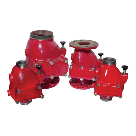
Johnson Controls Tyco TJPX0500003 User manual
Other Johnson Controls Control Unit manuals
Johnson Controls
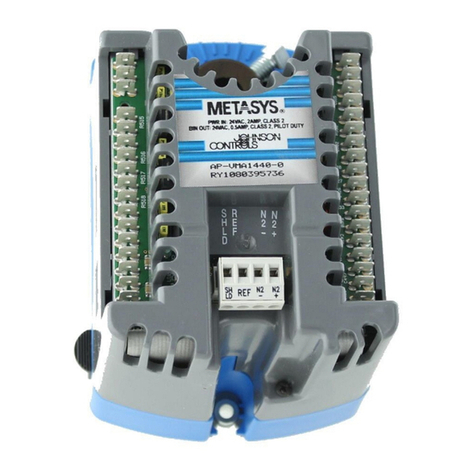
Johnson Controls VMA 1410 Installation guide
Johnson Controls
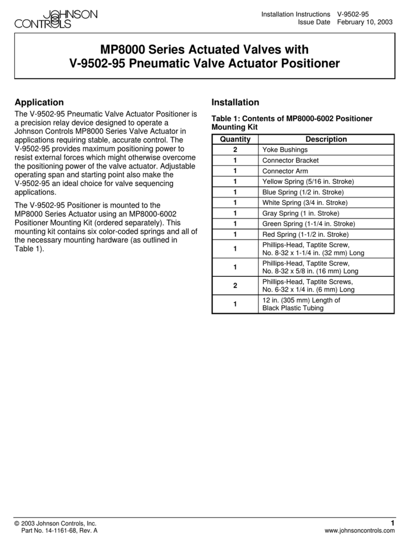
Johnson Controls MP8000 Series User manual

Johnson Controls
Johnson Controls IOM3711 User manual
Johnson Controls
Johnson Controls GS Series User manual
Johnson Controls
Johnson Controls Tyco 8200-1466-01 User manual
Johnson Controls
Johnson Controls M300CJ User manual
Johnson Controls
Johnson Controls Tyco RV-1A User manual
Johnson Controls
Johnson Controls Tyco DV-5a Series User manual
Johnson Controls
Johnson Controls S1-TTSCC01 Quick start guide
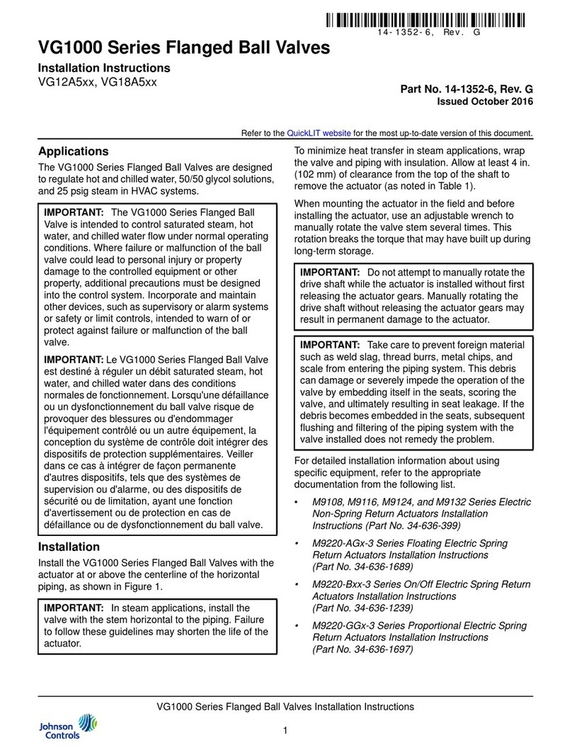
Johnson Controls
Johnson Controls VG1xA5Gx User manual
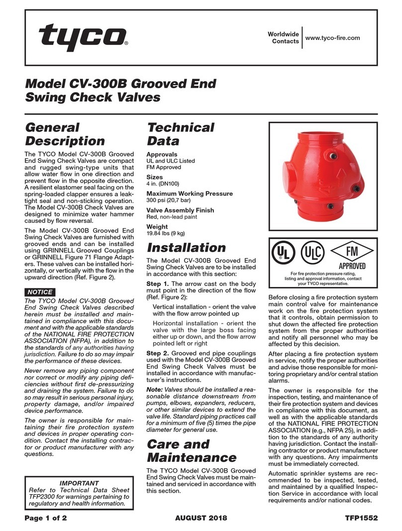
Johnson Controls
Johnson Controls Tyco CV-300B User manual
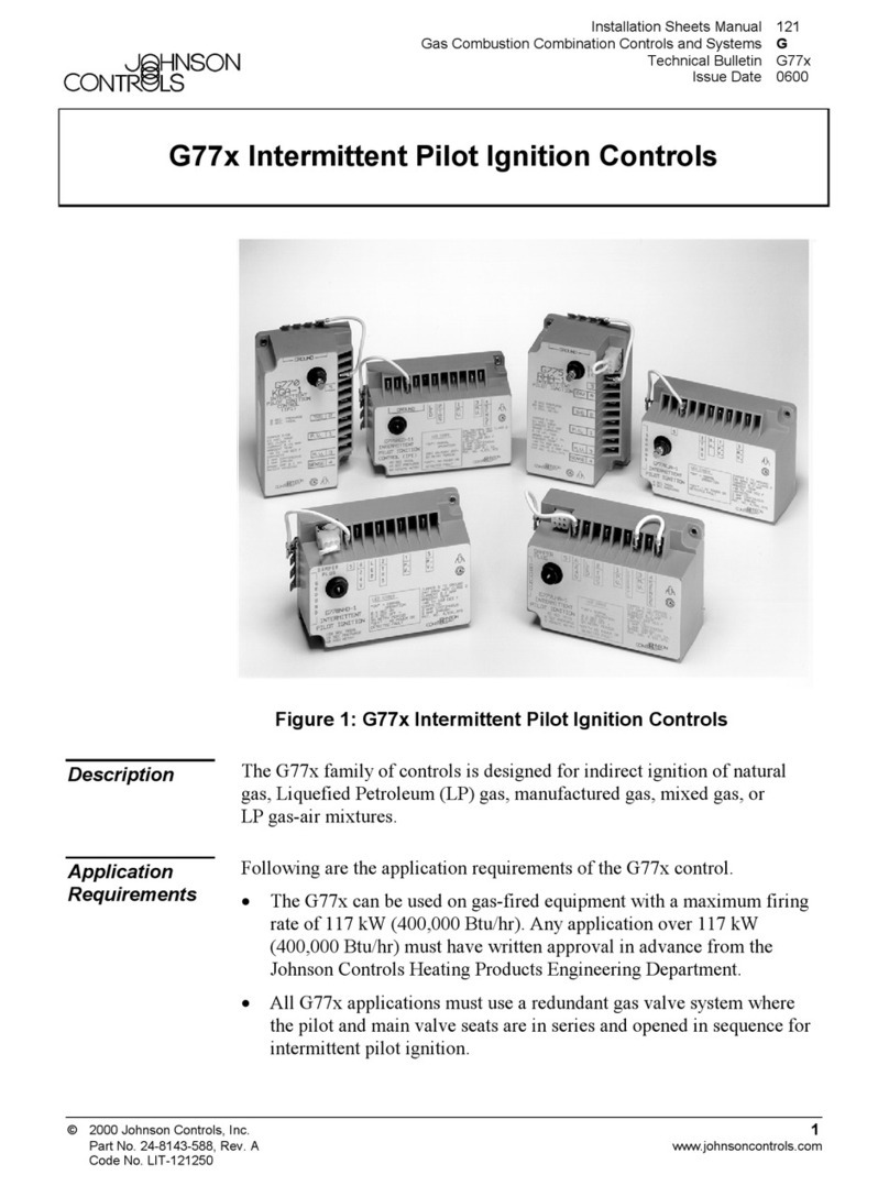
Johnson Controls
Johnson Controls G77 Series Service manual
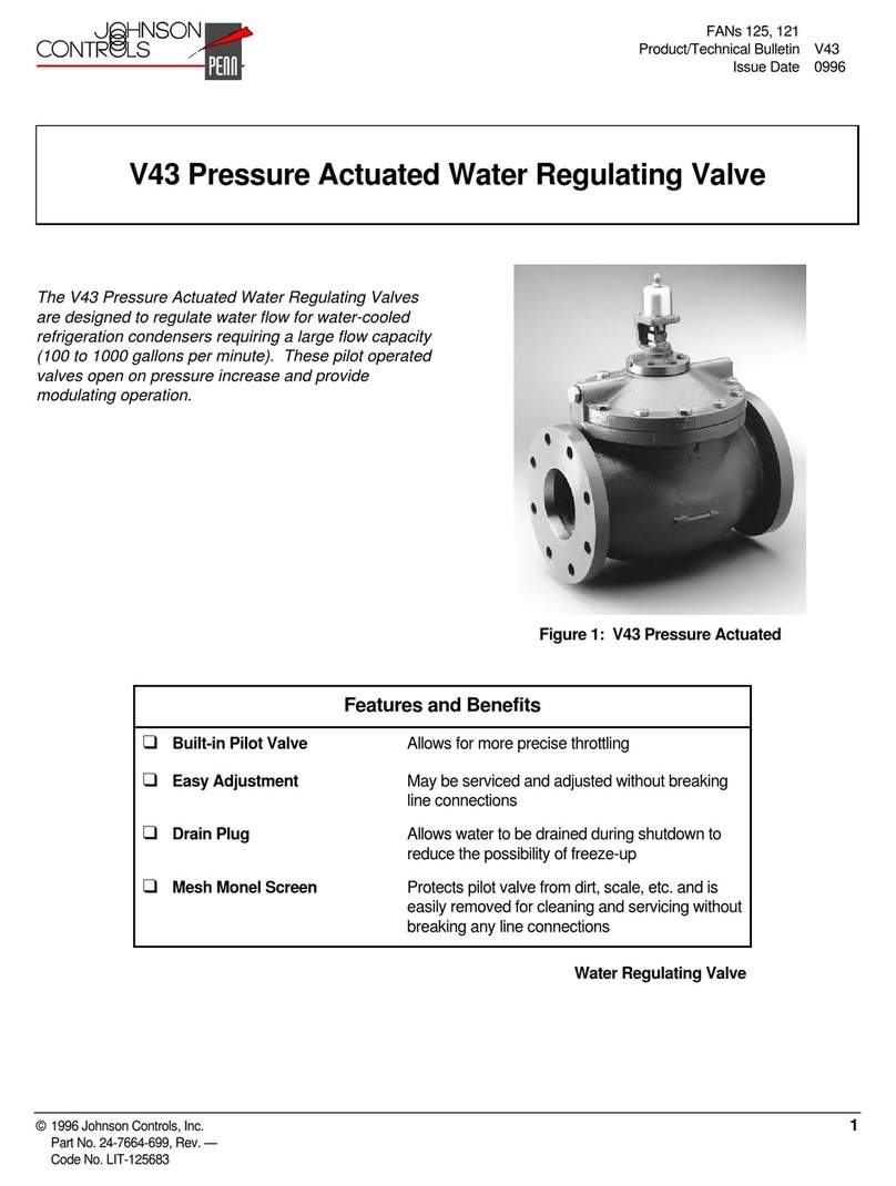
Johnson Controls
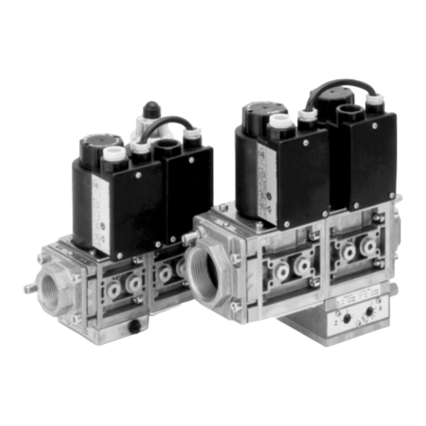
Johnson Controls V43 Series Manual
Johnson Controls
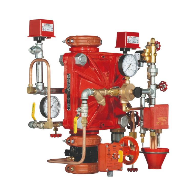
Johnson Controls GM 20 Series User manual
Johnson Controls
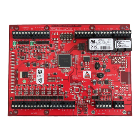
Johnson Controls Tyco DV-5a Series User manual
Johnson Controls
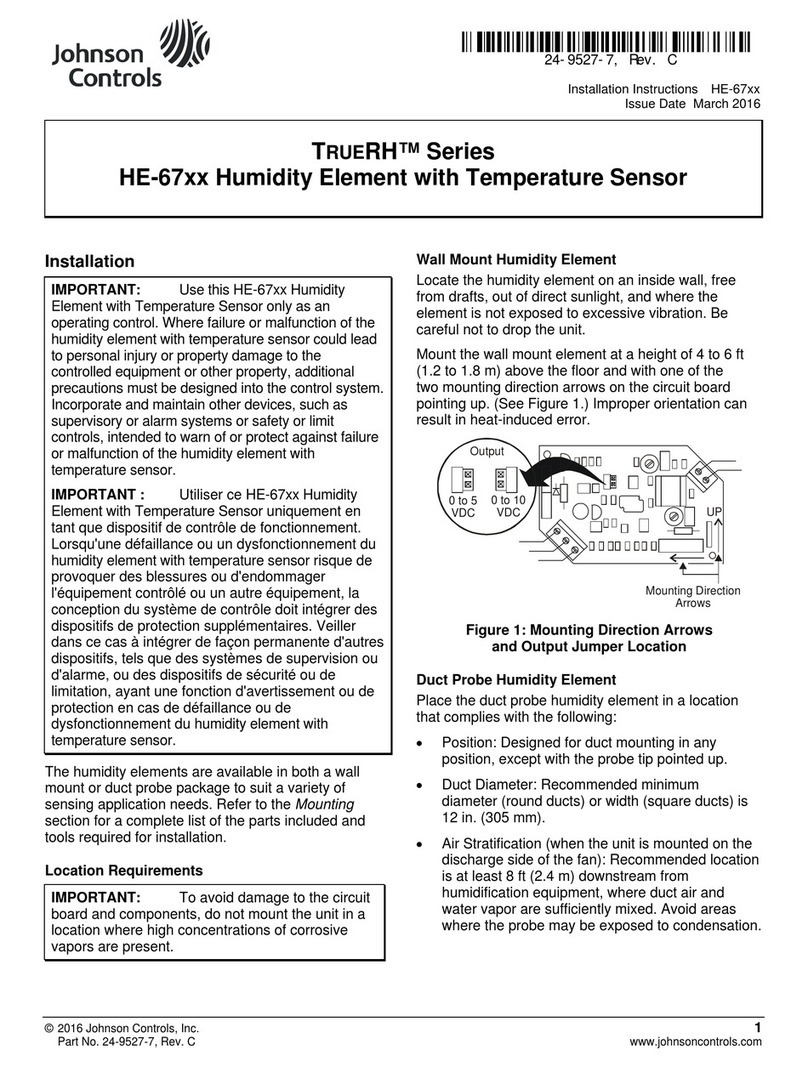
Johnson Controls Mercury 3 Series Manual
Johnson Controls
Johnson Controls TrueRH Series Guide

Johnson Controls
Johnson Controls VG8000V Series User manual
Johnson Controls
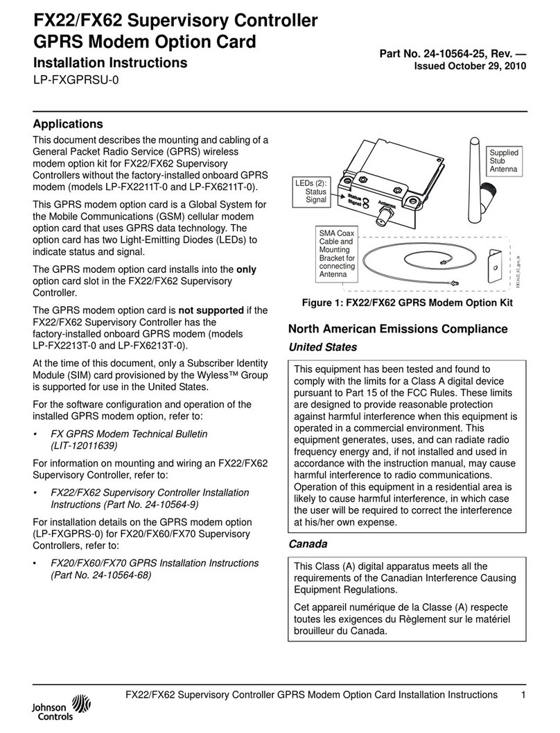
Johnson Controls LP-FXGPRSU-0 User manual
Johnson Controls
Johnson Controls Digital Vision Network 5000 Series Quick start guide
Popular Control Unit manuals by other brands

Festo
Festo Compact Performance CP-FB6-E Brief description

Elo TouchSystems
Elo TouchSystems DMS-SA19P-EXTME Quick installation guide

JS Automation
JS Automation MPC3034A user manual

JAUDT
JAUDT SW GII 6406 Series Translation of the original operating instructions

Spektrum
Spektrum Air Module System manual

BOC Edwards
BOC Edwards Q Series instruction manual

KHADAS
KHADAS BT Magic quick start

Etherma
Etherma eNEXHO-IL Assembly and operating instructions

PMFoundations
PMFoundations Attenuverter Assembly guide

GEA
GEA VARIVENT Operating instruction

Walther Systemtechnik
Walther Systemtechnik VMS-05 Assembly instructions

Altronix
Altronix LINQ8PD Installation and programming manual
