Rf-t SC-S User manual

www.rft.be
en
Rf-Technologies nv Lange Ambachtstraat 40 9860 Oosterzele Belgium Tel +32 9 362 31 71 Fax +32 9 362 33 07 [email protected]
S6-EN-A 02/2021
SC-S
Circular re damper cartridge for installation in a re resistant
suspended ceiling.

2Table of content
Table of content
Classifications overview 3
Product presentation SC-S 4
Range and dimensions SC-S 4
Storage and handling 5
Installation 5
Operation: manual closing 6
Operation: manual opening 7
Installation in a fire resistant suspended ceiling 8
Weights 10
Selection graphs 10
Sample order 12
Approvals and certificates 12
Explanation of the abbreviations and pictograms
Dn = nominal diameter
E = integrity
I = thermal insulation
S = smoke leakage
Pa = pascal
ve = vertical wall penetration
ho = horizontal floor penetration
i <-> o = fire side not important
o -> i = meets the criteria from the outside
(o) to the inside (i)
GKB (type A) / GKF (type F): “GKB”
stands for standard plasterboards (type
A according to EN 520) while “GKF”
plasterboards offer a higher fire resistance
for a similar plate thickness (type F
according to EN 520)
Sn = free air passage
ζ [-] = pressure loss coefficient
Q = airflow
∆P = static pressure drop
v = air speed in the duct
Lwa = A-weighted sound power level
OP = option (delivered with the product)
KIT = kit (delivered separately for repair or
upgrade)
DAS MOD = modular product
dB(A) = A-weighted decibel value
Lw oct = sound power level per octave
midband
∆L = correction factor
fast installation

3
Classications overview
A-02/2021Rf-t_S6_EN
Declarationofperformance
CE_DoP_Rf-t_S6_EN
A-02/2021
1. Unique identication code of the product-type: SC-S
2. Intended use/es: Circular re damper to be used in conjunction with partitions to maintain re compartments in heating, ventilating and air conditioning installations.
3. Manufacturer: Rf-Technologies NV, Lange Ambachtstraat 40, B-9860 Oosterzele
4. System/s of AVCP: System 1
6. Declared performance according to (Fire resistance according to EN 1366-2 and EN 1364-2)
Essential characteristics Performance
Range Wall type Wall Sealing Installation Classication
SC-S Ø 100-200 mm Fire resistant suspended ceiling Metal studs gypsum plasterboard Type F (EN 520) 2 x 12.5 mm Not applicable 1 EI 30 (hoo gi) S - (300Pa)
Metal studs gypsum plasterboard Type F (EN 520) 2 x 15 mm Not applicable 1 EI 60 (hoo gi) S - (300Pa)
1 Type of installation: built-in inside a duct, 0-360°; Fire side = side opposite to the fusible link
Nominal activation conditions/sensitivity: Pass
Response delay (response time): closure time Pass
Operational reliability: cycling 50 cycles
Durability of response delay: Pass
Durability of operational reliability: NPD (no performance determined)
Protection against corrosion according to EN 60068-2-52: NPD (no performance determined)
Harmonised standard
The performance of the product identied above is in conformity with the set of declared performance/s. This declaration of
performance is issued, in accordance with Regulation (EU) No 305/2011, under the sole responsibility of the manufacturer identi-
ed above.
Signed for and on behalf of the manufacturer by:
Mathieu Steenland, Technical Manager
Oosterzele, 02/2021

4Product presentation SC-S
Product presentation SC-S
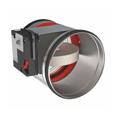
Circular fire damper cartridge with a finishing valve and collar for installation in a fire resistant suspended ceiling. Connection to a
ventilation system with flexible duct. For installation in fire-resistant EI30 and EI60 ceilings. The circular fire damper cartridges are
equipped with a fusible link that holds the two parts of the blade in the open position. When the temperature in the duct rises above
72°C, the fusible link melts and releases the two blades. The damper is now closed and two blocking hooks keep the blades in their
safety position, which prevents any smoke or flames from passing through.
1. SCV+ fire damper cartridge
2. damper blade
3. intumescent sealing
4. installation collar
5. flexible duct connection
6. blocking hooks
7. product identification
8. fixation spring
9. finishing collar
10.ventilation valve
1
9
8
3
4
2
5
6
7
10
Range and dimensions SC-S
ØDn+30
ØDn+50
130 46
ØDn-1
ØDn [mm] 100 125 160 200

5
Storage and handling
As this product is a safety element, it should be stored and handled with care.
Avoid:
• any kind of impact or damage
• contact with water
• deformation of the casing
Installation
General points
∎The installation must comply with the installation manual.
∎Verify if the blades can move freely.
∎Direction of the airflow: discretionary
∎SC-S fire damper cartridges are tested in standardised fire resistant suspended ceilings in accordance with EN 1366-2 and
EN 1364-2.
∎The fire damper cartridge must remain accessible for inspection and maintenance.
∎Please observe safety distances with respect to other construction elements.
100%
≥ 75 mm ≥ 200 mm
200%
SC+V

6Installation
Operation: manual closing
2. Unlock (close) the damper blades by pushing them towards
each other. Carefully unlock the fusible link by pushing it
sidewards.
1 2
3

7
Installation
Operation: manual opening
1.
2.
2. Press the two blocking hooks carefully to unlock the blades.
3. Click the fusible link into the holder to lock the blades.
1 2
3

8Installation
Installation in a fire resistant suspended ceiling
The product was tested and approved in:
Range Wall type Sealing Classication
SC-S Ø 100-200 mm Fire resistant suspended ceiling Metal studs gypsum plasterboard Type F (EN 520) 2 x 12.5 mm Not applicable EI 30 (hoo gi) S - (300Pa)
SC-S Ø 100-200 mm Fire resistant suspended ceiling Metal studs gypsum plasterboard Type F (EN 520) 2 x 15 mm Not applicable EI 60 (hoo gi) S - (300Pa)
100%
A
≤ 850
≤ 750
≤ 900
≤ 800
≤ 800
≤ 600
≤ 1000
≤ 1000
≤ 960
≤ 800
≤ 800
≤ 800
≤ 400
≤ 400
≤ 400
≤ 500
≤ 500
≤ 500
EI30S
EI60S
EI30S
E60
EI30
E60
A B C
C
B
2x 12.5mm (30’)
2x 15mm (60’)
Siniat
Knauf
Gyproc
1. Build the fire resistant suspended ceiling according to the
manufacturer’s instructions. Provide a piece a flexible duct to
connect the ventilation duct to the SC-S.
100%
100 130-137
125 155-162
160 190-197
200 230-237
ØDn Ø
2. Make a round opening in the fire resistant suspended ceiling,
with diameter as indicated in the table.
150%
3. Arm the fire damper cartridge as explained in the operating
instructions. Pull the flexible duct through the opening and
place it over the connection provided for the ventilation duct.
Attach the duct to the SC-S in an airtight manner.
Caution: Make sure that the damper blades are in open
position before installing into the ceiling.
150%
4. Press the retaining springs against the cylinder and slide the
SC-S in the opening. Push the SC-S all the way into the opening
so that the retaining springs lock above the ceiling.
1 2
3 4

9
Installation
150%
Plaster JointFiller
5. Finish with joint filler and allow to dry.
150%
6. Finally, install the finishing valve and adjust according to the
desired flow rate.
The use of another plastic finishing valve is permitted, as
long as it does not interfere with the operation of the damper
blades.
Maintenance
∎No specific maintenance required.
∎Schedule at least 2 visual checks each year.
∎Remove dust and all other particles before use.
∎Follow local maintenance regulations (i.e. BS9999 Annex V; NF S 61-933) and EN13306.
∎Warning: butterfly dampers, in their closed position, can move in the duct when placed under too high pressure.
5 6

10 Weights
Weights
SC-S
ØDn [mm] 100 125 160 200
kg 1,4 1,8 2,4 3,2
Selection graphs
a = number of complete revolutions of the valve. a = 0 = closed valve
0
50
100
150
200
250
0 20 40 60 80 100 120 140 160
a=5
a=11
a=15
a=21
LWA[dB(A)] 50
45
40
35
30
25
0
20
40
60
80
100
120
140
160
180
0 20 40 60 80 100 120 140 160
a=5
a=11
a=15
a=21
LWA[dB(A)]
45
50
40
35
30 25
Q[m3/h] Q[m3/h]
p[Pa]
p[Pa]
Ø 100
air exhaust air supply
0
20
40
60
80
100
120
140
160
0 50 100 150 200 250 300
a=5
a=11
a=15 a=21
LWA[dB(A)]50
45
40
35
30 25
0
20
40
60
80
100
120
140
160
180
200
0 50 100 150 200 250 300
a=5
a=11
a=15
a=21
45
40
35
30
25
LWA[dB(A)]
Q[m3/h] Q[m3/h]
p[Pa]
p[Pa]
Ø 125
air exhaust air supply

11
Selection graphs
0
20
40
60
80
100
120
140
0 50 100 150 200 250 350300
a=8
a=14
a=19
a=24
LWA[dB(A)] 45
40
35
30
25
20
0
50
100
150
200
250
0 50 100 150 200 250 300
350
a=8 a=14
a=19
a=24
45
40
35
30
25
20
LWA[dB(A)]
Q[m3/h] Q[m3/h]
p[Pa]
p[Pa]
Ø 160
air exhaust air supply
0
20
40
60
80
100
120
140
160
180
200
0 50 100 150 200 250 300 350
a=7
a=13
a=18
a=23
LWA[dB(A)] 50
45
40
35
30
25
20
0
20
40
60
80
100
120
140
160
180
0 50 100 150 200 250 300 350 400 450 500
a=7
a=13
a=18
a=23
LWA[dB(A)]
45
40
35
30
25
20
Q[m3/h] Q[m3/h]
p[Pa]
p[Pa]
Ø 200
air exhaust air supply

12 Sample order
Sample order
SC-S 125
21
1. product
2. diameter
Approvals and certicates
All our products are submitted to a number of tests by official test institutes. Reports of these tests form the basis for the approvals of
our dampers.
If the product is manipulated in any other way than described in this manual, Rf-Technologies will decline any responsibility and the guarantee will expire!
Table of contents
Other Rf-t Fire And Smoke Damper manuals
Popular Fire And Smoke Damper manuals by other brands
Broan
Broan MD6T user manual

Greenheck
Greenheck FD Series Installation instruction supplement
BSB
BSB FSD-C Installation, operating, & maintenance instructions

VPro
VPro WT Series instruction manual

Helios
Helios BRK Installation and operating instructions

Greenheck
Greenheck DFD Series Installation, operation and maintenance manual