manuals.online logo
Brands
  1. Home
  2. •
  3. Brands
  4. •
  5. Johnson Controls
  6. •
  7. Security Camera
  8. •
  9. Johnson Controls Holis JSV02-D02-OI01 User manual

Johnson Controls Holis JSV02-D02-OI01 User manual

This manual suits for next models

1

Other Johnson Controls Security Camera manuals

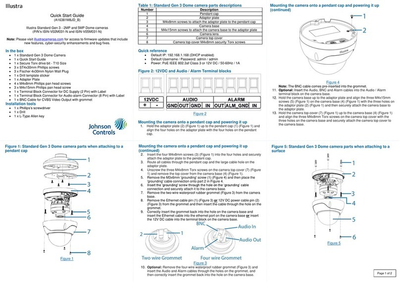
Johnson Controls tyco Illustra IBPN-M-IS-0 User manual

Johnson Controls

Johnson Controls tyco Illustra IBPN-M-IS-0 User manual

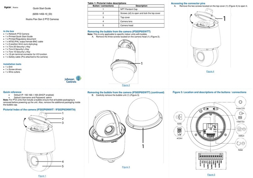
Johnson Controls Illustra Flex Gen 4 User manual

Johnson Controls

Johnson Controls Illustra Flex Gen 4 User manual

Johnson Controls Tyco Illustra User manual

Johnson Controls

Johnson Controls Tyco Illustra User manual

Johnson Controls Tyco Illustra Flex User manual

Johnson Controls

Johnson Controls Tyco Illustra Flex User manual

Johnson Controls tyco Illustra Pro User manual

Johnson Controls

Johnson Controls tyco Illustra Pro User manual

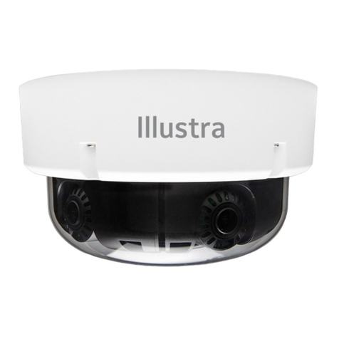
Johnson Controls Tyco Holis JSV User manual

Johnson Controls

Johnson Controls Tyco Holis JSV User manual

Johnson Controls Illustra PRO User manual

Johnson Controls

Johnson Controls Illustra PRO User manual

Johnson Controls Tyco Illustra Flex IFS03D1ICWTT Service manual

Johnson Controls

Johnson Controls Tyco Illustra Flex IFS03D1ICWTT Service manual

Johnson Controls TYCO Illustra Pro IPS02-P07-RT04 User manual

Johnson Controls

Johnson Controls TYCO Illustra Pro IPS02-P07-RT04 User manual

Johnson Controls Tyco Illustra Pro Gen4 User manual

Johnson Controls

Johnson Controls Tyco Illustra Pro Gen4 User manual

Johnson Controls Tyco Illustra Essentials Gen4 User manual

Johnson Controls

Johnson Controls Tyco Illustra Essentials Gen4 User manual

Johnson Controls Tyco Pro Gen2 User manual

Johnson Controls

Johnson Controls Tyco Pro Gen2 User manual

Johnson Controls Illustra Standard Gen 3 User manual

Johnson Controls

Johnson Controls Illustra Standard Gen 3 User manual

Popular Security Camera manuals by other brands

ADEMCO RapidDome Owners Operating & Installation Guide

ADEMCO

ADEMCO RapidDome Owners Operating & Installation Guide

EverFocus EBA2880 user manual

EverFocus

EverFocus EBA2880 user manual

Honeywell OptiCAM-IR Installation and setup guide

Honeywell

Honeywell OptiCAM-IR Installation and setup guide

Uniq UC-600 user manual

Uniq

Uniq UC-600 user manual

OPTICOM NVD-120-S datasheet

OPTICOM

OPTICOM NVD-120-S datasheet

Steren CCTV-221 instruction manual

Steren

Steren CCTV-221 instruction manual

Arm Electronics C420BCDNVFIR Features

Arm Electronics

Arm Electronics C420BCDNVFIR Features

Eneo PLD-2036PTZ installation guide

Eneo

Eneo PLD-2036PTZ installation guide

Axis AXIS M20 Series installation guide

Axis

Axis AXIS M20 Series installation guide

Panasonic KX-HCM230 operating instructions

Panasonic

Panasonic KX-HCM230 operating instructions

COP-USA CC15NV-SL Specifications

COP-USA

COP-USA CC15NV-SL Specifications

Active Silicon HARRIER H.264 quick start guide

Active Silicon

Active Silicon HARRIER H.264 quick start guide

Motorola Avigilon 1.3C-H5SL-BO1-IR installation guide

Motorola

Motorola Avigilon 1.3C-H5SL-BO1-IR installation guide

INSTEON 2864-232 user manual

INSTEON

INSTEON 2864-232 user manual

Wisenet XNB-6002 quick start guide

Wisenet

Wisenet XNB-6002 quick start guide

Axis M5525-E user manual

Axis

Axis M5525-E user manual

Vitek VTC-IR62NZ922 user guide

Vitek

Vitek VTC-IR62NZ922 user guide

Panasonic WV-SF342 Specifications

Panasonic

Panasonic WV-SF342 Specifications

manuals.online logo
manuals.online logoBrands
  • About & Mission
  • Contact us
  • Privacy Policy
  • Terms and Conditions

Copyright 2025 Manuals.Online. All Rights Reserved.

Figure 3: Micro SD card slot and camera buttons
Figure 3
Security
Quick Start Guide
(8200-1994-04_C0)
Tyco Holis JSV Versatile 2MP & JSA Advance 4MP IR Dome Cameras
(Product Code: JSV02-D02-OI01 and JSA04-D02-OI01)
In the box
1 x Camera
1 x Quick Start Guide
4 x PA 4x25mm tapping screws
1 x Mounting template
4 x 6x29mm Plastic screw anchors
1 x Sponge
1 x L-Key Hexagonal wrench
1 x CVBS & DC IN cables
1 x Regulatory Document
Installation tools
Screwdriver
Drill
L-Key Hexagonal wrench
Figure 1: Camera parts
Figure 1
Table 1: Camera part descriptions
Number
Camera part description
1
Camera base
2
Lock screw
3
Camera dome cover
4
Camera dome
Figure 2: Cable connections
Figure 2
Table 2: Cable connection descriptions
Number
Cable connection description
1
Ethernet Connector and also supports PoE
2
Audio Input (Mic)
3
Audio Output (HP)
4
CVBS Video Output
5
Alarm Input / Output
1 –Alarm OUT COM
2 –Alarm OUT Open
3 –Alarm IN
4 –Alarm IN GND
6
Power Connector (12V DC @ 1A)
7
Microphone
Figure 3: Micro SD card slot and camera buttons (continued)
Note: Remove the four screws on the camera cover (3) (Figure 1) to
access the buttons. Securely attach the cover when finished.
Table 3: Camera button descriptions and SD card slot
Number
Camera button description
1
Reset button (Hold for more than 3 seconds)
2
DC IN & CVBS Interface
3
Zoom -
4
Zoom +
5
Micro SD card slot
Quick reference
Default IP: 192.168.1.168 (DHCP enabled).
Default Username / Password: admin / admin
Power: 12VDC or PoE 48VDC (2MP also supports 24V AC).
Use Internet Explorer 11 web browser.
Mounting the camera to a wall or ceiling
Ensure that the wall or ceiling is strong enough to withstand three times
the weight of the camera.
1. Place the mounting template on the surface that you want to attach
the camera.
2. On the surface drill four Ø 6mm holes and cut out a Ø 22mm cable
hole as per the markings identified on the mounting template.
3. Securely place the four screw anchors into the four holes.
4. Remove the four screws on the camera cover (3) (Figure 1) and the
fixing screw (2) (Figure 1) to remove the cover from the camera
base.
Security
Mounting the camera to a wall or ceiling (continued)
5. Place the camera cable through the cable hole on the mounting
surface.
6. Align the four holes on the sponge (1) (Figure 4) with the four holes
on the camera base (2) (Figure 4).
Figure 4
7. Align the four holes on the sponge and camera base with the four
holes on the mounting template.
Mounting the camera to a wall or ceiling (continued)
8. Insert the four screws into the four holes on the camera base and
securely attach the sponger and camera base to the mounting
surface
9. Hold the camera base cover up to the camera base and align the
four holes on the camera cover with the four holes on the camera
base.
10. Insert the screws into the four holes and securely attach the
camera cover to the camera base.
11. Insert the fixing screw (2) (Figure 1) into the hole on the camera
base and securely attach it to the camera base.
12. To power up the camera:
Connect a 12V DC power supply to the power connector on
the camera cable.
OR
Connect a shielded PoE cable to the ethernet / PoE slot on
the camera cable.
Figure 5: Camera pan, tilt and rotate
Figure 5
Warnings
If the product does not work properly, please contact your dealer or
the nearest service centre. Never attempt to disassemble the
camera yourself. (We shall not be responsible for any problems
caused by unauthorized repair or maintenance.)
In the use of the product, you must be strict compliance with the
electrical safety regulations of the nation and region. When the
product is mounted on wall or ceiling, the device shall be firmly
fixed.
Do not allow water or liquid intrusion into the camera.
Do not use camera beyond specified voltage range.
Do not drop the camera or subject it to physical shock.
Avoid touching the camera lens.
If cleaning is necessary, please use clean cloth to wipe it gently.
Do not aim the camera at the sun or extra bright place.
Do not place the camera in extremely hot, cold (the operating
temperature shall be -30˚C~60˚C), dusty or damp locations, and
do not expose it to high electromagnetic radiation.
To avoid heat accumulation, good ventilation is required for
operating environment.
© 2021 Johnson Controls. All rights reserved.
JOHNSON CONTROLS, TYCO, and HOLIS are trademarks and/or
registered trademarks. Unauthorized use is strictly prohibited.