manuals.online logo
Brands
  1. Home
  2. •
  3. Brands
  4. •
  5. Johnson Controls
  6. •
  7. Security Camera
  8. •
  9. Johnson Controls tyco Illustra Pro User manual

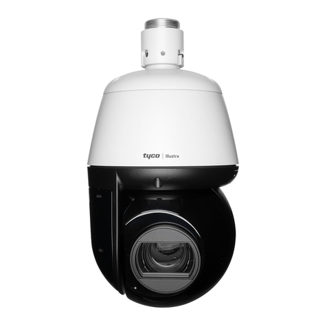
Johnson Controls tyco Illustra Pro User manual

Figure 3: Camera interface (Base assembly side)
Figure 3
Security
Quick Start Guide
(8200-2007-07_C0)
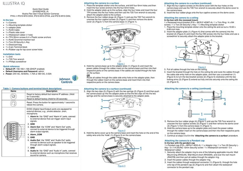
Illustra Pro Gen4, 2MP, 4MP & 8MP Indoor / Outdoor IR Dome cameras
Note: Please visit illustracameras.com for access to firmware updates that include
new features, cyber-security enhancements and bug fixes.
In the box
1 x Camera
1 x T20 Security Key
4 x TP4 32mm screws & 4 x Plastic screw anchors
1 x Water proof rubber (1 hole)
1 x Water proof rubber (3 holes)
1 x Water proof rubber insert tool
1 x Printed Regulatory Document
1 x Printed QSG
1 x Camera bottom base (use in a wall mount installation)
1 x Camera bottom base cable hole cover
1 x Mounting template (use with the bottom case / wall mount installation)
1 x Mounting template (use in an in-ceiling mount installation)
1 x Metal cover
Installation tools
1 x Screw driver
1 x Drill
1 x Wire cutters
Figure 1: PG4 Indoor / Outdoor IR Dome camera parts
Figure 1
Table 1: Camera parts descriptions
Number
Description
1
Camera bottom base
2
Dome cover base
3
Dome
Quick reference
Default IP: 192.168.1.168 (DHCP enabled)
Default Username / Password: admin / admin
Power: PoE Class 3 or 24V AC
Table 2: Camera interface (Bubble assembly side)
Number
Description
1
USB port connection
2
Reboot button
3
Auto focus (Set the camera focus during installation)
4
Reset to Factory default but preserve IP Address (Hold for 5
seconds)
Reset to factory default (Hold for 20 seconds)
Figure 2: Camera interface (Bubble assembly side)
Note: Use the T20 security key to remove the three screws on the dome cover (2)
(Figure 1) to access the interior buttons and USB connection.
Figure 2
Table 3: Camera interface (Base assembly side)
Number
Description
1
Ethernet port
2
Micro HDMI cable port
3
Mini USB cable port
4
Micro SD card slot
5
Audio and alarm pins
6
Power connector
Mounting the camera
Refer to the Illustra mounting accessories webpage
https://www.illustracameras.com/products/accessories/mounts for
assistance. The following mount accessory part numbers are
applicable with the Illustra Pro Gen4 2MP, 4MP and 8MP IR Indoor /
Outdoor Dome cameras: ADCi6DPCAPOW, ADLOMARM,
ADCDMCRNRO, ADCDMPOLE and IBJB-P-ISWB-0.
Installing the camera onto a wall or ceiling
1. Use the T20 security key to remove the three screws on the dome cover (2)
(Figure 1).
2. Use a screw driver to remove the safety lanyard screw that is connecting the
dome cover to the camera. Note: The dome cover is now completely
disconnected from the camera.
3. Insert all cables through one of the waterproof rubbers:
a) if you are using the three hole waterproof rubber then pierce three holes
as per the three circles on the rubber, insert the cable through the three
rubber holes and then terminate the cable.
OR
a) if you are using the one hole waterproof rubber then pull the rubber pin
to make the cable hole, insert the terminated cable into the insert tool
and then pull the insert tool through the hole.
4. Hold the guide pattern sticker up to the surface and drill four 6mm holes and
if you are not using the cable side entry hole on the bottom case then cut out
a cable entry hole on the surface as per the guide pattern.
Note: If you are not using the cable side entry hole then insert the cable
cover.
5. Use a hammer to insert the four screw anchors (1) (Figure 8) into the holes
6. Hold the camera bottom case (2) (Figure 8) up to the surface and align the
four 6mm holes on the surface with the four holes in the bottom case
(remove the rubber inserts in the bottom case first).
7. Insert the four TP 32mm screws (3) (Figure 8) and securely attach the bottom
case to the surface.
8. Pull the camera power cables through the cable hole on the surface or the
side entry hole on the bottom case.
9. Hold the camera (4) (Figure 8) up to the bottom case and connect the cables
to their respective ports on the camera.
10. Insert the camera into the bottom case and use a T20 security key to
securely attach the camera to the bottom base with the three T10 screws.
Figure 4
Security
Installing the camera into a recess ceiling
1. Hold the guide pattern sticker up to the ceiling (1) (Figure 4) and cut out a
125mm hole.
2. Use the T20 security key to remove the three screws on the dome cover (2)
(Figure 1).
3. Use a screw driver to remove the safety lanyard screw that is connecting the
dome cover to the camera. Note: The dome cover is now completely
disconnected from the camera.
4. Place the camera power cables through the hole in the ceiling and the metal
cover (2) (Figure 4).
Figure 4
Installing the camera in to a recess ceiling (continued)
5. Connect the cables to their respective ports on the camera.
6. Align the two screws on the metal cover (1) (Figure 5) with the two holes on
the camera and use a screw driver to securely attach the metal cover to the
camera.
Figure 5
7. Push the camera cable back into the hole in the ceiling and hold the camera
up to the hole in the ceiling.
8. Use a cross screw driver and turn both captive screws (1) (Figure 6) on the
camera clockwise to extend out the locking arms (2) (Figure 6), then rotate
the two captive screws anti-clockwise until the locking arms sit securely to the
ceiling.
Installing the camera in to a recess ceiling (continued)
Figure 6
9. Adjust the camera lens position as follows. See Figure 7.
Pan Adjustment (1): Rotate the lens base until you are satisfied with
the field of view.
Tilt Adjustment (2): Tilt the eye-ball assembly as needed.
Note: Limitation for the two axes position: Pan range = ±380° /
Tilt range = 15°~90°.
Installing the camera in to a recess ceiling (continued)
Figure 7
10. Insert the dome cover safety lanyard screw into the camera and securely
attach the dome cover to the camera.
11. Hold the dome cover up to the camera and align the three screws in the
dome cover with the three holes on the camera.
12. Use the T20 security key to securely attach the three screws to the camera.
Installing the camera onto a wall or ceiling (continued)
11. Adjust the camera lens position as per step 9 in the Installing the camera in
to a recess ceiling procedure.
12. Screw the safety lanyard screw into the camera so that the dome cover is
attached to the camera.
13. Hold the dome cover (5) (Figure 8) up to the camera and align the three
screws in the dome cover with the three holes on the camera.
14. Use the T20 security key to securely attach the three screws to the camera.
Figure 8
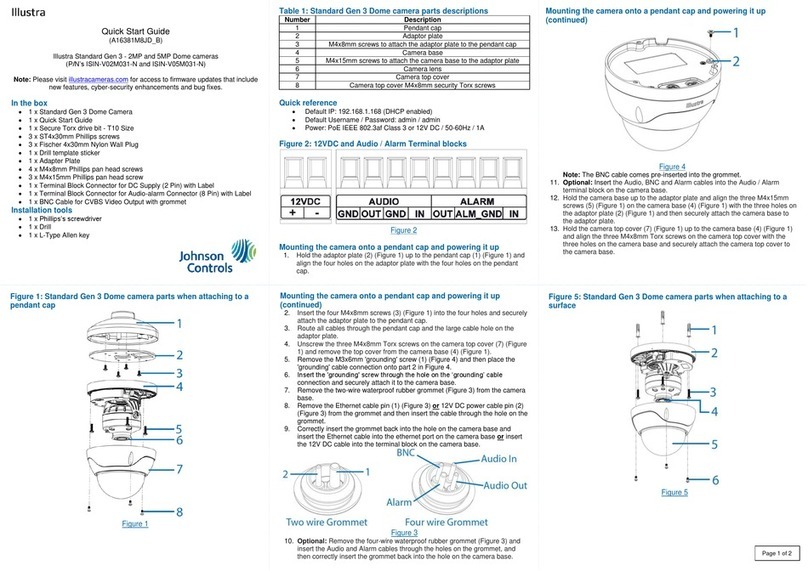
Table 4: Camera part numbers and descriptions
Part Number
Description
IPS02-D12-OI04
Illustra Pro Gen4 2MP MiniDome, 2.7-13.5mm,
Indoor/Outdoor, IP67, IK10, TDN w/IR, TWDR
IPS02-D17-OI04
Illustra Pro Gen4 2MP MiniDome, 7-22mm, Indoor/Outdoor,
IP67, IK10, TDN w/IR, TWDR
IPS04-D12-OI04
Illustra Pro Gen4 4MP MiniDome, 2.7-13.5mm,
Indoor/Outdoor, IP67, IK10, TDN w/IR, TWDR
IPS04-D14-OI04
Illustra Pro Gen4 4MP MiniDome, 6-22mm, Indoor/Outdoor,
IP67, IK10, TDN w/IR, TWDR
IPS08-D13-OI04
Illustra Pro Gen4 8MP MiniDome, 3.6-11mm,
Indoor/Outdoor, IP67, IK10, TDN w/IR, TWDR
IPS08-D14-OI04
Illustra Pro Gen4 8MP MiniDome, 6-22mm, Indoor/Outdoor,
IP67, IK10, TDN w/IR, TWDR
Security
Installing the camera onto a surface with a recessed junction box
1. See steps 1, 2, and 3 in the Installing the camera onto a wall or ceiling
procedure.
2. Insert the four screws anchors onto the four holes on the junction box (1)
(Figure 8).
3. Hold the camera bottom case (2) (Figure 8) up to the junction box and align
the four holes on the camera bottom case with the four holes on the junction
box
4. Insert the four TP 32mm screws (3) (Figure 8) and securely attach the bottom
case to the junction box.
Figure 8
Installing the camera onto a surface with a recessed junction box
(continued)
5. See steps 8 to 14 in the Installing the camera onto a wall or ceiling
procedure to complete the installation.
Installing the camera onto a surface with a junction box
1. See steps 1, 2, and 3 in the Installing the camera onto a wall or ceiling
procedure.
2. Insert the four screws anchors onto the four holes on the junction box (1)
(Figure 9).
3. Hold the camera bottom case (2) (Figure 9) up to the junction box and align
the four holes on the camera bottom case with the four holes on the junction
box
4. Insert the four TP 32mm screws (3) (Figure 9) and securely attach the bottom
case to the junction box.
5. See steps 8 to 14 in the Installing the camera onto a wall or ceiling
procedure to complete the installation.
Installing the camera onto a surface with a junction box (continued)
Figure 9
Warnings
1. Installation and service should be performed only by qualified and experienced
technicians and comply with all local codes and rules to maintain your warranty.
2. Wipe the camera with a dry soft cloth. For tough stains, slightly apply with diluted
neutral detergent and wipe with a dry soft cloth.
3. Do not apply benzene or thinner to the camera, which may cause the surface of
the unit to be melted or lens to be fogged.
4. To Meet EU EMC immunity requirements for security equipment the mains
power for equipment powering this unit should be backed up by an
uninterruptible power supply.
5. Avoid operating or storing the unit in the following locations:
Near fluorescent lamps or objects with reflections.
Under unstable or flickering light sources.
© 2021 Johnson Controls. All rights reserved. JOHNSON CONTROLS, TYCO and
ILLUSTRA are trademarks and/or registered trademarks. Unauthorized use is strictly
prohibited.

Other Johnson Controls Security Camera manuals

Johnson Controls Illustra Standard Gen 3 User manual

Johnson Controls

Johnson Controls Illustra Standard Gen 3 User manual

Johnson Controls Tyco Illustra User manual

Johnson Controls

Johnson Controls Tyco Illustra User manual

Johnson Controls Illustra PRO User manual

Johnson Controls

Johnson Controls Illustra PRO User manual

Johnson Controls Illustra Flex Gen 4 User manual

Johnson Controls

Johnson Controls Illustra Flex Gen 4 User manual

Johnson Controls TYCO Illustra Pro IPS02-P07-RT04 User manual

Johnson Controls

Johnson Controls TYCO Illustra Pro IPS02-P07-RT04 User manual

Johnson Controls Holis JSV02-D02-OI01 User manual

Johnson Controls

Johnson Controls Holis JSV02-D02-OI01 User manual

Johnson Controls Tyco Holis JSV User manual

Johnson Controls

Johnson Controls Tyco Holis JSV User manual

Johnson Controls Tyco Illustra Flex User manual

Johnson Controls

Johnson Controls Tyco Illustra Flex User manual

Johnson Controls Tyco Illustra Flex IFS03D1ICWTT Service manual

Johnson Controls

Johnson Controls Tyco Illustra Flex IFS03D1ICWTT Service manual

Johnson Controls Tyco Illustra Pro Gen4 User manual

Johnson Controls

Johnson Controls Tyco Illustra Pro Gen4 User manual

Johnson Controls tyco Illustra IBPN-M-IS-0 User manual

Johnson Controls

Johnson Controls tyco Illustra IBPN-M-IS-0 User manual

Johnson Controls Tyco Pro Gen2 User manual

Johnson Controls

Johnson Controls Tyco Pro Gen2 User manual

Johnson Controls Tyco Illustra Essentials Gen4 User manual

Johnson Controls

Johnson Controls Tyco Illustra Essentials Gen4 User manual

Popular Security Camera manuals by other brands

Honeywell HCX13MW Specifications

Honeywell

Honeywell HCX13MW Specifications

Vezco VZ-IP-2MLPRB installation manual

Vezco

Vezco VZ-IP-2MLPRB installation manual

Monacor TVCCD-182HCOL operating instructions

Monacor

Monacor TVCCD-182HCOL operating instructions

DSE RKK Series installation manual

DSE

DSE RKK Series installation manual

Panasonic BL-C210 Series operating instructions

Panasonic

Panasonic BL-C210 Series operating instructions

American Dynamics Discover Indoor datasheet

American Dynamics

American Dynamics Discover Indoor datasheet

IMAGO ICN-11P1 NW 2.8 Quick installation guide

IMAGO

IMAGO ICN-11P1 NW 2.8 Quick installation guide

Panasonic WV-U2500 Series operating instructions

Panasonic

Panasonic WV-U2500 Series operating instructions

Bosch AutoDome VG5-825-ECEV Specifications

Bosch

Bosch AutoDome VG5-825-ECEV Specifications

Vitek VTC-C661 Specifications

Vitek

Vitek VTC-C661 Specifications

Berger & Schroter 32034 operating instructions

Berger & Schroter

Berger & Schroter 32034 operating instructions

Axis M5013-V datasheet

Axis

Axis M5013-V datasheet

D-Link DCS-932L user manual

D-Link

D-Link DCS-932L user manual

GeoVision GV-GVS2100 user manual

GeoVision

GeoVision GV-GVS2100 user manual

Burg Wächter SNC-841DFIF Quick installation guide

Burg Wächter

Burg Wächter SNC-841DFIF Quick installation guide

Plustek IPCam P1000 Specifications

Plustek

Plustek IPCam P1000 Specifications

Samsung iPolis SNB-5000 Technical specifications

Samsung

Samsung iPolis SNB-5000 Technical specifications

Ezviz C2C-FHD manual

Ezviz

Ezviz C2C-FHD manual

manuals.online logo
manuals.online logoBrands
  • About & Mission
  • Contact us
  • Privacy Policy
  • Terms and Conditions

Copyright 2025 Manuals.Online. All Rights Reserved.