manuals.online logo
Brands
  1. Home
  2. •
  3. Brands
  4. •
  5. Johnson Controls
  6. •
  7. Security Camera
  8. •
  9. Johnson Controls Tyco Pro Gen2 User manual

Johnson Controls Tyco Pro Gen2 User manual

Mounting the camera to a wall and powering it up
(continued)
Figure 3
Security
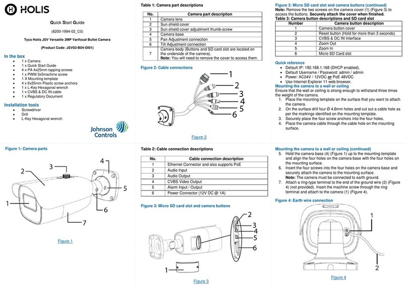
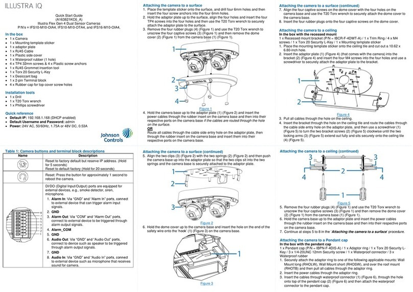
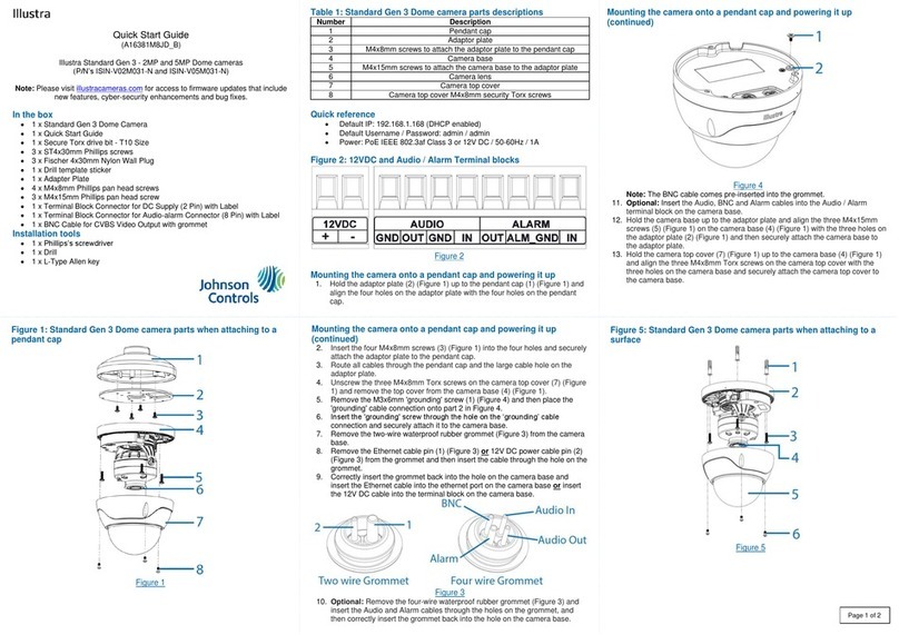
Quick Start Guide
(8200-1984-01_B0)
Illustra Pro Gen2 12MP Fisheye camera
(P/N IPS12-F27-OI02)
In the box
1 x Illustra Pro Gen2 12MP Fisheye Camera
1 x Security Torx L-Key
1 x Mounting template sticker
1 x Adaptor plate
1 x Standoff ring
3 x ‘4.8x24.7mm’ plastic screw anchors
6 x ‘M4*8H’screws with flat spring and washer (Adaptor plate & Pendant)
6 x ‘8-32UNC*5/16H’screws (Standoff ring, 4s electrical box)
3 x M3 Self-tapping screws (without washer)
3 x M3 Standard screws (without washer)
1 x Printed Quick Start Guide
1 x 2 pin terminal block
1 x Desiccant bag
1 x 12cm/5” tape
1 x ‘O’ ring
1 x Rubber cable seal
Installation tools
1 x Screw driver
1 x Security Torx L-Key
1 x Drill
Quick reference
Default IP: 192.168.1.168 (DHCP enabled)
Default Username / Password: admin / admin
Power: PoE or DC 12V
Note: To provide maximum protection against condensation, replace the
desiccant bag each time the top cover is removed.
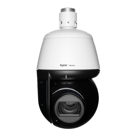
Figure 1: Pro Gen2 12MP Fisheye camera
Figure 1
Mounting the camera to a wall and powering it up
1. Place the mounting template sticker on the wall.
2. On the wall drill two Ø 8.01mm holes and cut out an Ø 31.5mm
cabling hole as per the markings identified on the mounting
template sticker.
3. Insert the two ‘4.8x24.7mm’ plastic screw anchors into the two Ø
8.01mm holes.
4. Use the Torx L-key to loosen the two screws (Figure 2) on the
camera cover and remove the camera cover from the camera
base.
Figure 2
Mounting the camera to a wall and powering it up
(continued)
5. Insert the power cable through the cable hole and hold the camera
base up to the wall and connect the DC 12V cable to a DC 12V
terminal or connect the RJ-45 jack to a PoE compatible network
device that supplies power through the ethernet cable.
6. Align the two holes on the camera base with the two holes on the
wall, insert the two M3 self-tapping screws into the two holes and
securely attach the camera base to the wall.
7. Remove the desiccant bag from its sealed bag and remove the
protective membrane from the desiccant bag.
8. Insert the desiccant bag into the camera. See this location in
Figure 3.
9. Hold the camera cover up to the camera base and align the two
captive screws on the camera cover with the two threaded holes
on the camera base.
10. Use the Torx L-key to secure the two camera cover screws (Figure
2) to the camera base.
Mounting the camera to an electrical box and powering it up
You can mount the camera to a 4s electrical box, a single gang electrical
box or a dual gang electrical box.
1. Remove the electrical box cover.
2. Hold the standoff ring up to the electrical box and align the four
holes on the standoff ring with the four holes on the electrical box.
3. Insert four 8-32UNC*5/16H’ screws into the four holes and
securely attach the standoff ring to the electrical box.
4. Use the Torx L-key to loosen the two screws (Figure 2) on the
camera cover and remove the camera cover from the camera
base.
5. Insert the power cable through the cable hole on the standoff ring
and hold the camera base up to the standoff ring and connect the
DC 12V cable to a DC 12V terminal or connect the RJ-45 jack to a
PoE compatible network device that supplies power through the
ethernet cable.
6. Align the two holes on the camera base with the two holes on the
standoff ring, insert the two M3 standard screws into the two holes
and securely attach the camera base to the standoff ring.
7. Remove the desiccant bag from its sealed bag and remove the
protective membrane from the desiccant bag.
8. Insert the desiccant bag into the camera. See this location in
Figure 3.
9. Hold the camera cover up to the camera base and align the two
captive screws on the camera cover with the two threaded holes
on the camera base.
10. Use the Torx L-key to secure the two camera cover screws (Figure
2) to the camera base.
Inserting the cable through the cable seal (continued)
1. Locate the rubber cable seal (Figure 6) on the underside of the
camera body.
Figure 6
Note: There are three tubes on the cable seal, two closed and one
open.
2. Insert the power cable through the ‘open’ tube on the cable seal.
Note: If additional cables are required then cut the top of the other
two tubes and insert a cable into one or both tubes.
Note: Ensure that there are no gaps between the cables and the
tubes.
Security
Mounting the camera to a tilt mount
IPFETILMOUNT (tilt mount) accessory is applicable with the camera.
See https://illustracameras.com/accessories/ for further information.
1. Use the Torx L-key to loosen the two screws (Figure 2) on the
camera cover and remove the cover from the camera base.
2. Insert the power cable through the cable hole on the tilt mount and
hold the camera base up to the tilt mount and connect the DC 12V
cable to a DC 12V terminal or connect the RJ-45 jack to a PoE
compatible network device that supplies power through the
ethernet cable.
3. Align the two holes on the camera base with the two holes on the
tilt mount, insert the two M3 standard screws into the two holes
and securely attach the camera base to the tilt mount.
4. Remove the desiccant bag from its sealed bag and remove the
protective membrane from the desiccant bag.
5. Insert the desiccant bag into the camera. See this location in
Figure 3.
6. Hold the camera cover up to the camera base and align the two
captive screws on the camera cover with the two threaded holes
on the camera base.
7. Use the Torx L-key to secure the two camera cover screws (Figure
2) to the camera base.
Mounting the camera to a wall mount or pendant cap
ADCiM6WALLWK (wall mount) and ADCi6DPCAPOW (pendant cap)
accessories are applicable with the camera. See
https://illustracameras.com/accessories/ for further information.
1. Hold the adaptor plate up to the accessory and align the four
holes on the adaptor plate with the four holes on the accessory.
2. Insert four ‘M4*8H’ screws into the four holes and securely attach
the adaptor plate to the accessory.
3. Use the Torx L-key to loosen the two screws (Figure 2) on the
camera cover and remove the cover from the camera base.
4. Insert the power cable through the cable hole on the adaptor plate
and hold the camera base up to the adaptor plate and connect the
DC 12V cable to a DC 12V terminal or connect the RJ-45 jack to
a PoE compatible network device that supplies power through the
ethernet cable.
5. Align the two holes on the camera base with the two holes on the
adaptor plate, insert the two M3 standard screws into the two
holes and securely attach the camera base to the adaptor plate.
6. Remove the desiccant bag from its sealed bag and remove the
protective membrane from the desiccant bag.
7. Insert the desiccant bag into the camera. See this location in
Figure 3.
8. Hold the camera cover up to the camera base and align the two
captive screws on the camera cover with the two threaded holes
on the camera base.
9. Use the Torx L-key to secure the two camera cover screws
(Figure 2) to the camera base.
Figure 4 and 5: Camera button / connections
Figure 4
Figure 5
Table 1: Camera button / connection descriptions
Camera Part
Description
Comments
1
RJ-45 (PoE
connection)
Network connection
2
Power (DC 12V
power connection)
Power connection
3
microSD Card Slot
Insert the microSD card into the
card slot to store videos and
snapshots. Do not remove the
microSD card when the camera
is powered on.
4
Alarm & Audio I/O
(Do NOT connect
external power
supply to the alarm
I/O connector of
the camera).
1 –Alarm out +
2 –Alarm out –
3 –Alarm In +
4 –Alarm In –
5 –GND
6 –Audio Out (Line Out)
7 –Audio In (Line In)
5
Factory default
button
Press the button with a proper
tool for at least 20 seconds to
restore the system.
Inserting the cable through the cable seal
Where conduit is not being used, sealing the cables that are fed through
the cable seal is required. This is to protect the camera and maintain
camera performance. Note: The cable seal is located on the underside
of the camera body.
Inserting the cable through the cable seal (continued)
3. To add further protection to the cable then use the self-fusing tape
provided and wrap it around the point where the cable enters the
tube.
Warnings
This product is intended for professional installation, please follow local
wiring regulations.
This camera must be installed by qualified personnel and the installation
should conform to all local codes.
Do not replace batteries of the camera. Risk of explosion may occur if the
battery is replaced by an incorrect type.
To use an external power supply, please contact the camera manufacturer
to confirm that the power supply complies with the LPS requirements and
shares the same power specifications with the camera.
Please use a DC 12V power adaptor and plug it to the camera and the
power outlet. Alternatively, users can use an Ethernet cable and connect it
to the RJ-45 connector of the camera and a Power Sourcing Equipment
(PSE) switch.
This product is intended to be supplied by a listed power adaptor or DC
power source marked ‘’L.P.S.’’ (or ‘’Limited Power Supply’’), rated 12Vdc,
0.93A minimum or 48Vdc, 0.27A minimum (for PoE), Tma = 55 degree C
minimum. If you need further assistance, please contact Dynacolor Inc. for
further information.
© 2020 Johnson Controls. All rights reserved. JOHNSON CONTROLS, TYCO and
ILLUSTRA are trademarks and/or registered trademarks. Unauthorized use is strictly
prohibited.

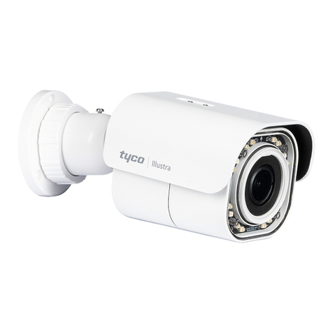
This manual suits for next models

1

Other Johnson Controls Security Camera manuals

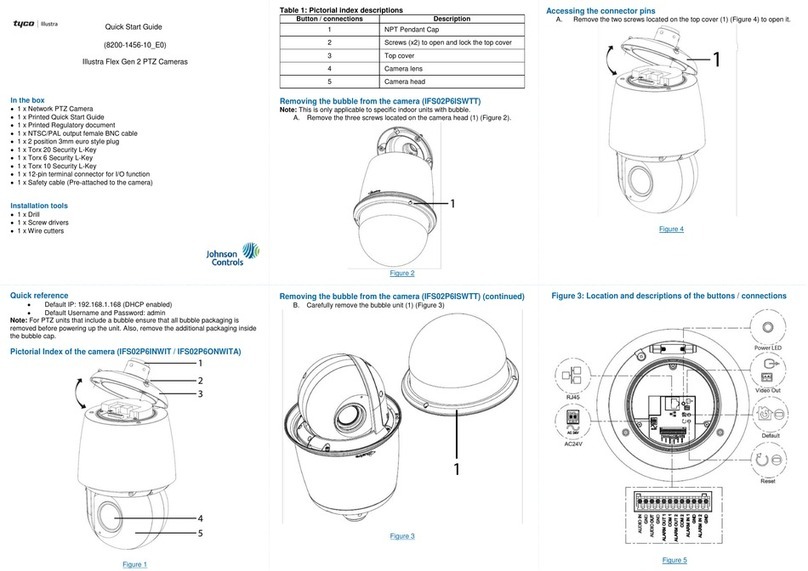
Johnson Controls tyco Illustra Pro User manual

Johnson Controls

Johnson Controls tyco Illustra Pro User manual

Johnson Controls Illustra Flex Gen 4 User manual

Johnson Controls

Johnson Controls Illustra Flex Gen 4 User manual

Johnson Controls Illustra Standard Gen 3 User manual

Johnson Controls

Johnson Controls Illustra Standard Gen 3 User manual

Johnson Controls Illustra PRO User manual

Johnson Controls

Johnson Controls Illustra PRO User manual

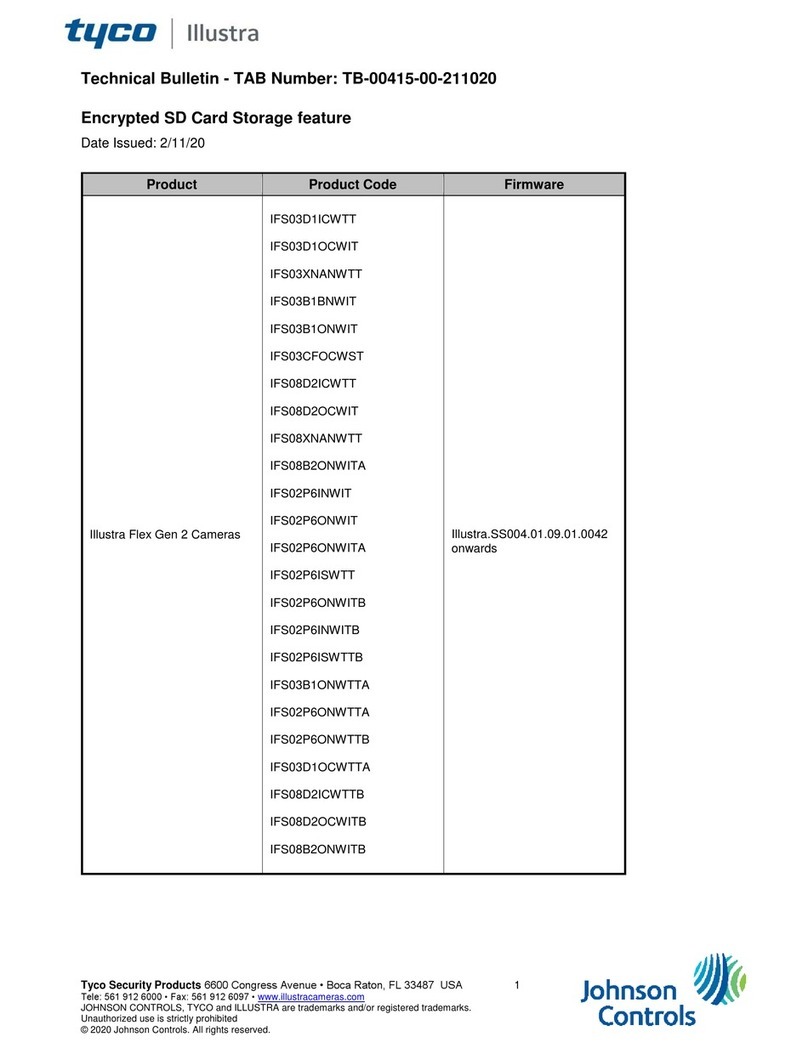
Johnson Controls tyco Illustra IBPN-M-IS-0 User manual

Johnson Controls

Johnson Controls tyco Illustra IBPN-M-IS-0 User manual

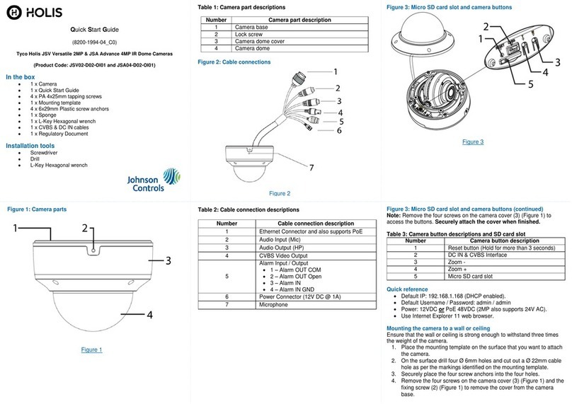
Johnson Controls Tyco Holis JSV User manual

Johnson Controls

Johnson Controls Tyco Holis JSV User manual

Johnson Controls Tyco Illustra Flex User manual

Johnson Controls

Johnson Controls Tyco Illustra Flex User manual

Johnson Controls Tyco Illustra User manual

Johnson Controls

Johnson Controls Tyco Illustra User manual

Johnson Controls Tyco Illustra Flex IFS03D1ICWTT Service manual

Johnson Controls

Johnson Controls Tyco Illustra Flex IFS03D1ICWTT Service manual

Johnson Controls Tyco Illustra Pro Gen4 User manual

Johnson Controls

Johnson Controls Tyco Illustra Pro Gen4 User manual

Johnson Controls Holis JSV02-D02-OI01 User manual

Johnson Controls

Johnson Controls Holis JSV02-D02-OI01 User manual

Johnson Controls Tyco Illustra Essentials Gen4 User manual

Johnson Controls

Johnson Controls Tyco Illustra Essentials Gen4 User manual

Johnson Controls TYCO Illustra Pro IPS02-P07-RT04 User manual

Johnson Controls

Johnson Controls TYCO Illustra Pro IPS02-P07-RT04 User manual

Popular Security Camera manuals by other brands

Eneo IPD-62M2812P0A user manual

Eneo

Eneo IPD-62M2812P0A user manual

Nite Devil CAM620 manual

Nite Devil

Nite Devil CAM620 manual

MachPower SM-BCW2M-001 Quick installation guide

MachPower

MachPower SM-BCW2M-001 Quick installation guide

Idis DC-T6223HRL Operation manual

Idis

Idis DC-T6223HRL Operation manual

Meari Flight 4T quick guide

Meari

Meari Flight 4T quick guide

Interlogix TVB-5501 installation guide

Interlogix

Interlogix TVB-5501 installation guide

Vitek VT-PTZ10 user manual

Vitek

Vitek VT-PTZ10 user manual

Axis EVI-D30 installation guide

Axis

Axis EVI-D30 installation guide

DivioTec NBR225P user manual

DivioTec

DivioTec NBR225P user manual

Panasonic WV-V1330LK manual

Panasonic

Panasonic WV-V1330LK manual

ZKTeco FC700 installation manual

ZKTeco

ZKTeco FC700 installation manual

Ezviz H3c user manual

Ezviz

Ezviz H3c user manual

Samsung SCC-C6455N user manual

Samsung

Samsung SCC-C6455N user manual

CBC Ganz ZC-NH406P instruction manual

CBC

CBC Ganz ZC-NH406P instruction manual

Arm Electronics C420BCIR100 Specification sheet

Arm Electronics

Arm Electronics C420BCIR100 Specification sheet

TRENDnet TV-IP322WI user guide

TRENDnet

TRENDnet TV-IP322WI user guide

THOMSON 512503 quick start guide

THOMSON

THOMSON 512503 quick start guide

dallmeier Picodome DDF4220HDV Series Configuration guide

dallmeier

dallmeier Picodome DDF4220HDV Series Configuration guide

manuals.online logo
manuals.online logoBrands
  • About & Mission
  • Contact us
  • Privacy Policy
  • Terms and Conditions

Copyright 2025 Manuals.Online. All Rights Reserved.