manuals.online logo
Brands
  1. Home
  2. •
  3. Brands
  4. •
  5. Johnson Controls
  6. •
  7. Security Camera
  8. •
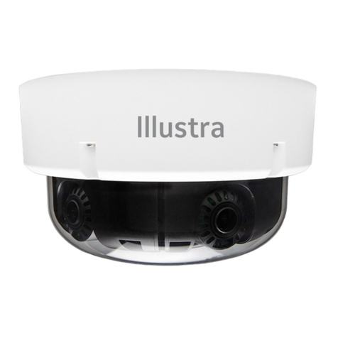
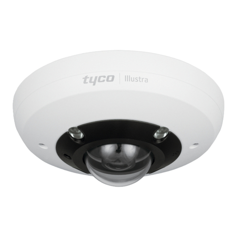
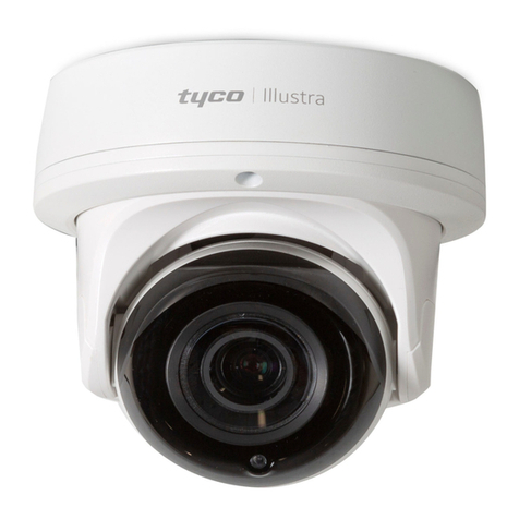
  9. Johnson Controls tyco Illustra IBPN-M-IS-0 User manual

Johnson Controls tyco Illustra IBPN-M-IS-0 User manual

This manual suits for next models

3

Other Johnson Controls Security Camera manuals

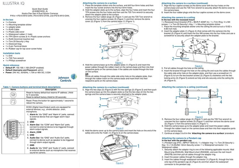
Johnson Controls Illustra Flex Gen 4 User manual

Johnson Controls

Johnson Controls Illustra Flex Gen 4 User manual

Johnson Controls Illustra PRO User manual

Johnson Controls

Johnson Controls Illustra PRO User manual

Johnson Controls Tyco Illustra Essentials Gen4 User manual

Johnson Controls

Johnson Controls Tyco Illustra Essentials Gen4 User manual

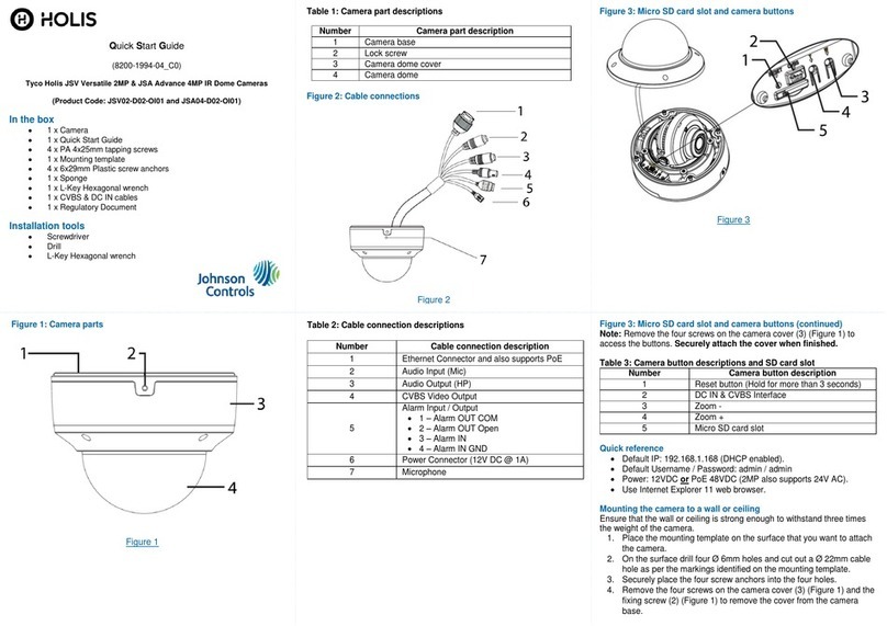
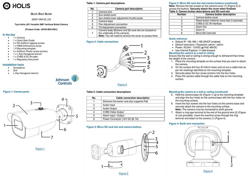
Johnson Controls Tyco Holis JSV User manual

Johnson Controls

Johnson Controls Tyco Holis JSV User manual

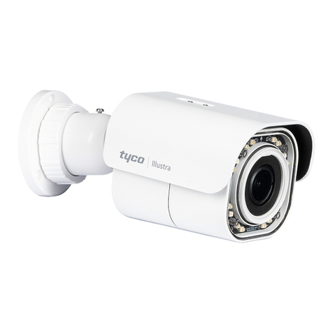
Johnson Controls Tyco Illustra User manual

Johnson Controls

Johnson Controls Tyco Illustra User manual

Johnson Controls Tyco Illustra Flex User manual

Johnson Controls

Johnson Controls Tyco Illustra Flex User manual

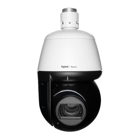
Johnson Controls TYCO Illustra Pro IPS02-P07-RT04 User manual

Johnson Controls

Johnson Controls TYCO Illustra Pro IPS02-P07-RT04 User manual

Johnson Controls tyco Illustra Pro User manual

Johnson Controls

Johnson Controls tyco Illustra Pro User manual

Johnson Controls Illustra Standard Gen 3 User manual

Johnson Controls

Johnson Controls Illustra Standard Gen 3 User manual

Johnson Controls Tyco Illustra Pro Gen4 User manual

Johnson Controls

Johnson Controls Tyco Illustra Pro Gen4 User manual

Johnson Controls Tyco Illustra Flex IFS03D1ICWTT Service manual

Johnson Controls

Johnson Controls Tyco Illustra Flex IFS03D1ICWTT Service manual

Johnson Controls Holis JSV02-D02-OI01 User manual

Johnson Controls

Johnson Controls Holis JSV02-D02-OI01 User manual

Johnson Controls Tyco Pro Gen2 User manual

Johnson Controls

Johnson Controls Tyco Pro Gen2 User manual

Popular Security Camera manuals by other brands

ADEMCO RapidDome Owners Operating & Installation Guide

ADEMCO

ADEMCO RapidDome Owners Operating & Installation Guide

EverFocus EBA2880 user manual

EverFocus

EverFocus EBA2880 user manual

Honeywell OptiCAM-IR Installation and setup guide

Honeywell

Honeywell OptiCAM-IR Installation and setup guide

Uniq UC-600 user manual

Uniq

Uniq UC-600 user manual

OPTICOM NVD-120-S datasheet

OPTICOM

OPTICOM NVD-120-S datasheet

Steren CCTV-221 instruction manual

Steren

Steren CCTV-221 instruction manual

Arm Electronics C420BCDNVFIR Features

Arm Electronics

Arm Electronics C420BCDNVFIR Features

Eneo PLD-2036PTZ installation guide

Eneo

Eneo PLD-2036PTZ installation guide

Axis AXIS M20 Series installation guide

Axis

Axis AXIS M20 Series installation guide

Panasonic KX-HCM230 operating instructions

Panasonic

Panasonic KX-HCM230 operating instructions

COP-USA CC15NV-SL Specifications

COP-USA

COP-USA CC15NV-SL Specifications

Active Silicon HARRIER H.264 quick start guide

Active Silicon

Active Silicon HARRIER H.264 quick start guide

Motorola Avigilon 1.3C-H5SL-BO1-IR installation guide

Motorola

Motorola Avigilon 1.3C-H5SL-BO1-IR installation guide

INSTEON 2864-232 user manual

INSTEON

INSTEON 2864-232 user manual

Wisenet XNB-6002 quick start guide

Wisenet

Wisenet XNB-6002 quick start guide

Axis M5525-E user manual

Axis

Axis M5525-E user manual

Vitek VTC-IR62NZ922 user guide

Vitek

Vitek VTC-IR62NZ922 user guide

Panasonic WV-SF342 Specifications

Panasonic

Panasonic WV-SF342 Specifications

manuals.online logo
manuals.online logoBrands
  • About & Mission
  • Contact us
  • Privacy Policy
  • Terms and Conditions

Copyright 2025 Manuals.Online. All Rights Reserved.

Mount Installation (IBWS-M-ISWB-0) continued
Figure 2
Quick Start Guide
(8200-1938-05_D0)
Flex Gen 2 Multi Sensor Dome Camera
Mounting Accessories Quick Start Guide
Note: You must securely attach one of the camera mounts in the table
below to the surface that you want to attach the camera. When the mount
is installed then the camera is securely attached to the mount. Follow the
steps in the Camera Installation procedure to secure the camera to the
mount.
Mount Product Code
Description on label
IBPN-M-IS12-0
Flex Multi-sensor Ceiling bracket
IBWS-M-ISWB-0
Flex Multi-sensor Wall bracket
IBCR-M-ISWT-0
Flex Multi-sensor In-Ceiling bracket
IBJB-M-ISWB-0
Flex Multi-sensor Junction bracket
In the box (IBPN-M-IS12-0)
1 x Ceiling bracket mount
4 x Screws and screw anchors (attaching the pole to the ceiling)
2 x Mounting screws (attaching the camera to the mount cover)
1 x Safety lanyard (plus two spare lanyard ends)
1 x Quick Start Guide
1 x Mounting Template sticker
1 x Mounting plate (for attaching the pole to the ceiling)
1 x Allen wrench
1 x Driver bit
Installation tools (IBPN-M-IS12-0)
Drill
Allen wrench
Screwdriver
Mount Installation (IBPN-M-IS12-0)
1. Place the mounting template sticker on to the ceiling and drill four holes, cut
out a cable hole and then insert the four screw anchors into the four holes.
2. Align the holes on the mounting plate with the holes on the mounting pole base
(1) (Figure 1) and hold both up to the ceiling.
3. Align the four holes on the mounting pole base with the four holes on the
ceiling.
4. Insert the four screws into the four holes on the mounting plate and securely
attach the mount cover to the mounting pole.
5. Attach the safety lanyard to the ‘hook’ on the mount cover (2) (Figure 1) and
the ‘hook’ on the camera base.
6. Follow the steps in the Camera Installation procedure to secure the camera to
the mount.
Figure 1
In the box (IBWS-M-ISWB-0)
1 x Wall bracket mount
2 x Mounting screws (these attach the camera to the mount)
4 x Screws and screw anchors
1 x Safety lanyard (plus two spare lanyard ends)
1 x Quick Start Guide
1 x Mounting Template sticker
1 x Mounting plate
Installation tools (IBWS-M-ISWB-0)
Drill
Screwdriver
Mount Installation (IBWS-M-ISWB-0)
1. Place the mounting template sticker on to the mounting surface and drill
four screw holes, cut out a cable hole and then insert the four screw
anchors into the four screw holes.
2. Align the holes on the mounting plate with the holes on the wall mount base
(1) (Figure 2) and hold the mounting plate and wall mount base up to the
mounting surface.
3. Align the four holes on the mount base with the four holes on the surface.
4. Insert the four screws into the four holes on the mounting base and
securely attach the base to the mounting surface.
5. Attach the safety lanyard (2) (Figure 2) to the ‘hook’ on the mount cover
and the ‘hook’ on the camera base.
6. Follow the steps in the Camera Installation procedure to secure the camera
to the mount.
In the box (IBCR-M-ISWT-0)
1 x In-Ceiling bracket mount
1 x Eye bolt
1 x Quick Start Guide
1 x Mounting Template sticker
2 x Safety lanyard
2 x Mounting screws (secures the camera to the mount)
Mount installation (IBCR-M-ISWT-0)
1. Place the mounting template sticker on to the ceiling and cut out a large hole
as per the markings on the mounting template.
2. Attach one end of the safety lanyard to a secure structure or object in the
ceiling and screw in the eye bolt (1) (Figure 3) to the top of the mount.
3. Attach the other end of the safety lanyard (2) (Figure 3) to the eye-bolt on the
mount.
4. Pull the ‘wings-tabs’ (3) (Figure 3) out to tighten the mount against the ceiling.
Note: You can rotate the screw (4) (Figure 3) to adjust the ‘wings-tabs’ up or
down.
Note: There are three ‘wing-tabs’ on the mount.
5. Attach the other safety lanyard to the ‘hook’ within the mount and the ‘hook’
on the camera base.
6. Follow the steps in the Camera Installation procedure to secure the camera
to the mount.
Camera Installation (continued)
Figure 7
3. To securely attach the camera base to the mount you must insert the two
mounting screws provided with the mount into the two holes on the camera
base (Figure 9).
4. Adjust the four camera modules (Figure 8) on to the four magnetics on the
camera base to ensure the best view.
Note: Align the four camera modules as per one of the three examples
shown in Figure 8.
Note: Ensure that the camera modules are level with the dome and that the
base guide is resting flat on the magnetic track.
Figure 8
Security
Mount installation (IBCR-M-ISWT-0) continued
Figure 3
In the box (IBJB-M-ISWB-0)
•1 - Junction bracket mount
•2 - Mounting screws (these attach the camera to the mount)
•4 - Screws and screw anchors
•1 - Safety lanyard
•1 - Quick Start Guide
•1 - Mounting Template sticker
•4 - #8-32 3/4"" screws (for use with a '4-11/16" ' electrical box)
•2 - #6-32 x 1/2" screws (for use with a single-gang’ electrical box)
Installation tools (IBJB-M-ISWB-0)
•Drill
•Screwdriver
Mount Installation (IBJB-M-ISWB-0)
You can attach the junction bracket mount directly to a wall / ceiling surface or to a
‘single-gang’ electrical box or '4-11/16" ' electrical box.
1. Wall / ceiling installation: Place the mounting template sticker on to the
mounting surface and drill four screw holes, cut out a cable hole and then
insert the four screw anchors into the four screw holes.
OR
Electrical box installation: Align the four holes on the junction bracket
mount (1) (Figure 4) with the four holes on the mounting surface or ‘4-11/16’’
electrical box (2) (Figure 4) or align the two holes on the junction bracket
mount (1) (Figure 5) with two holes on the single gang electrical box (2)
(Figure 5).
2. Insert the four / two screws into the four / two holes on the junction mount
bracket and securely attach the mount to the mounting surface or electrical
box.
3. Attach the safety lanyard to the ‘hook’ on the mount cover (1) (Figure 6) and
the ‘hook’ on the camera base.
Mount Installation (IBJB-M-ISWB-0) continued
4. Follow the steps in the Camera Installation procedure to secure the camera
to the mount.
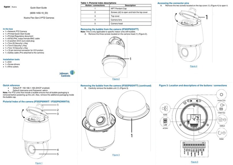
Figure 4 Figure 5
Mount Installation (IBJB-M-ISWB-0) continued
Figure 6
Camera Installation
1. Hold the camera base up to the mount and place all cables through the
cable hole on the camera mount.
2. Align the two metal pins on the top of the camera base with the two holes
on the mount and rotate the camera base so that the camera base sits into
the mount.
Note: The bridge on the camera base (Figure 7) aligns with the ‘lock’ and
‘unlock’ bridges on the mount.
Camera Installation (continued)
Figure 9
Note: Ensure that the camera module angle does not exceed 60 degrees.
See Figure 10.
Security
Camera Installation (continued)
Figure 10
5. Use the Torx wrench to securely attach the dome cover to the camera base.
6. Remove the outer protective film from the dome cover to complete the
installation.
© 2021 Johnson Controls. All rights reserved.
JOHNSON CONTROLS, TYCO and ILLUSTRA are trademarks and/or registered
trademarks. Unauthorized use is strictly prohibited.