manuals.online logo
Brands
  1. Home
  2. •
  3. Brands
  4. •
  5. Johnson Controls
  6. •
  7. Security Camera
  8. •
  9. Johnson Controls Illustra Standard Gen 3 User manual

Johnson Controls Illustra Standard Gen 3 User manual

Mounting the camera onto a pendant cap and powering it up
(continued)
Figure 4
Note: The BNC cable comes pre-inserted into the grommet.
11. Optional: Insert the Audio, BNC and Alarm cables into the Audio / Alarm
terminal block on the camera base.
12. Hold the camera base up to the adaptor plate and align the three M4x15mm
screws (5) (Figure 1) on the camera base (4) (Figure 1) with the three holes on
the adaptor plate (2) (Figure 1) and then securely attach the camera base to
the adaptor plate.
13. Hold the camera top cover (7) (Figure 1) up to the camera base (4) (Figure 1)
and align the three M4x8mm Torx screws on the camera top cover with the
three holes on the camera base and securely attach the camera top cover to
the camera base.
Figure 5: Standard Gen 3 Dome camera parts when attaching to a
surface
Figure 5
Security
Quick Start Guide
(A16381M8JD_B)
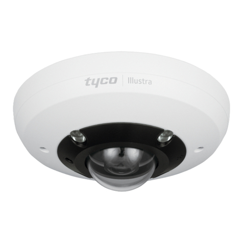
Illustra Standard Gen 3 - 2MP and 5MP Dome cameras
(P/N’s ISIN-V02M031-N and ISIN-V05M031-N)
Note: Please visit illustracameras.com for access to firmware updates that include
new features, cyber-security enhancements and bug fixes.
In the box
•1 x Standard Gen 3 Dome Camera
•1 x Quick Start Guide
•1 x Secure Torx drive bit - T10 Size
•3 x ST4x30mm Phillips screws
•3 x Fischer 4x30mm Nylon Wall Plug
•1 x Drill template sticker
•1 x Adapter Plate
•4 x M4x8mm Phillips pan head screws
•3 x M4x15mm Phillips pan head screw
•1 x Terminal Block Connector for DC Supply (2 Pin) with Label
•1 x Terminal Block Connector for Audio-alarm Connector (8 Pin) with Label
•1 x BNC Cable for CVBS Video Output with grommet
Installation tools
•1 x Phillips’s screwdriver
•1 x Drill
•1 x L-Type Allen key
Figure 1: Standard Gen 3 Dome camera parts when attaching to a
pendant cap
Figure 1
Table 1: Standard Gen 3 Dome camera parts descriptions
Number
Description
1
Pendant cap
2
Adaptor plate
3
M4x8mm screws to attach the adaptor plate to the pendant cap
4
Camera base
5
M4x15mm screws to attach the camera base to the adaptor plate
6
Camera lens
7
Camera top cover
8
Camera top cover M4x8mm security Torx screws
Quick reference
•Default IP: 192.168.1.168 (DHCP enabled)
•Default Username / Password: admin / admin
•Power: PoE IEEE 802.3af Class 3 or 12V DC / 50-60Hz / 1A
Figure 2: 12VDC and Audio / Alarm Terminal blocks
Figure 2
Mounting the camera onto a pendant cap and powering it up
1. Hold the adaptor plate (2) (Figure 1) up to the pendant cap (1) (Figure 1) and
align the four holes on the adaptor plate with the four holes on the pendant
cap.
Mounting the camera onto a pendant cap and powering it up
(continued)
2. Insert the four M4x8mm screws (3) (Figure 1) into the four holes and securely
attach the adaptor plate to the pendant cap.
3. Route all cables through the pendant cap and the large cable hole on the
adaptor plate.
4. Unscrew the three M4x8mm Torx screws on the camera top cover (7) (Figure
1) and remove the top cover from the camera base (4) (Figure 1).
5. Remove the M3x6mm 'grounding' screw (1) (Figure 4) and then place the
'grounding' cable connection onto part 2 in Figure 4.
6. Insert the 'grounding' screw through the hole on the ‘grounding’ cable
connection and securely attach it to the camera base.
7. Remove the two-wire waterproof rubber grommet (Figure 3) from the camera
base.
8. Remove the Ethernet cable pin (1) (Figure 3) or 12V DC power cable pin (2)
(Figure 3) from the grommet and then insert the cable through the hole on the
grommet.
9. Correctly insert the grommet back into the hole on the camera base and
insert the Ethernet cable into the ethernet port on the camera base or insert
the 12V DC cable into the terminal block on the camera base.
Figure 3
10. Optional: Remove the four-wire waterproof rubber grommet (Figure 3) and
insert the Audio and Alarm cables through the holes on the grommet, and
then correctly insert the grommet back into the hole on the camera base.
Page 1 of 2
Adjusting the camera position
1. Unscrew the three screws on the camera top cover (3) (Figure 6) and remove
the top cover from the camera base (2) (Figure 6).
•To rotate the camera lens: rotate the 3-axis gimbal (1) (Figure 8)
between 0°and 355°.
•To tilt the camera lens: tilt the 3-axis gimbal (2) (Figure 8) between 0°
and 75°.
•To pan the camera lens: rotate the 3-axis gimbal (1) (Figure 8)
between 0°and 355°.
Figure 8
Inserting or removing an SD card
1. Loosen the two M2.5x6mm captive screws (?) (Figure 4) on the SD
card cover to insert or remove the SD card (?) (Figure 4).
Security
Table 2: Standard Gen 3 Dome camera parts descriptions
Number
Description
1
4x30mm nylon wall plugs
2
Camera base
3
ST4x30mm screws to attach the camera base to the surface
4
Camera lens
5
Camera top cover
6
Camera top cover M4x8mm Torx screws
Mounting the camera onto a surface and powering it up
1. Place the drill template sticker on to the surface and mark out three holes.
These holes are identified with a ‘1’ on the template sticker.
2. Drill three 5.5mm holes on the surface and then insert the three 4x30mm wall
plugs (1) (Figure 5) into the three holes.
3. You can route all camera cables through cable holes on the surface, or you
can route all cables through the cable side entry hole on the camera base.
a) If you are routing the cables through the surface, then cut out two cable
holes on the surface. These holes are identified with an ‘A’ and ‘B’ on
the template sticker.
4. Unscrew the three M4x8mm Torx screws (6) (Figure 5) on the camera top
cover (5) (Figure 5) and remove the top cover from the camera base (2)
(Figure 5).
5. Hold the camera base up to the surface and route the cables through the cable
side entry hole on the camera base if you are not routing the cables through
the cable holes on the surface.
6. Remove the M3x6mm 'grounding' screw (1) (Figure 4) and then place the
'grounding' cable connection onto part 2 in Figure 4.
7. Insert the 'grounding' screw through the hole on the ‘grounding’ cable
connection and securely attach it to the camera base.
8. Remove the two-wire waterproof rubber grommet (Figure 3) from the camera
base.
9. Remove the Ethernet cable pin (1) (Figure 3) or 12V DC power cable pin (2)
(Figure 3) from the grommet and then insert the cable through the hole on the
grommet.
Mounting the camera onto a surface and powering it up (continued)
10. Correctly insert the grommet back into the hole on the camera base and insert
the Ethernet cable into the ethernet port on the camera base or insert the 12V
DC cable into the terminal block on the camera base.
11. Optional: Remove the four-wire waterproof rubber grommet (Figure 3) and
insert the Audio and Alarm cables through the holes on the grommet, and then
correctly insert the grommet back into the hole on the camera base.
Note: The BNC cable comes pre-inserted into the grommet.
12. Optional: Insert the Audio, BNC and Alarm cables into the Audio / Alarm
terminal block on the camera base.
13. Hold the camera base up to the surface and align the three ST4x30mm screws
(3) (Figure 4) on the camera base (2) (Figure 4) with the three holes on the
surface and then securely attach the camera base to the surface.
14. Hold the camera top cover (5) (Figure 4) up to the camera base (2) (Figure 4)
and align the three M4x8mm Torx screws on the camera top cover with the
three holes on the camera base and securely attach the camera top cover to
the camera base.
Inserting or removing an SD card
1. Unscrew the three screws on the camera top cover (3) (Figure 6) and
remove the top cover from the camera base (2) (Figure 6).
2. Insert or remove the SD card (1) (Figure 6) from the SD card slot.
Figure 6
Accessing the cameras internal buttons and connections
1. Unscrew the three screws on the camera top cover (3) (Figure 6) and
remove the top cover from the camera base (2) (Figure 6) to access the
internal buttons and connections.
Note: See Table 3 for descriptions for each part identified in Figure 7.
Inserting or removing an SD card
1. Loosen the two M2.5x6mm captive screws (?) (Figure 4) on the SD
card cover to insert or remove the SD card (?) (Figure 4).
Accessing the cameras internal buttons and connections (continued)
Figure 7
Table 3: Camera internal buttons and connection descriptions
Number
Description
1
Reboots the unit
2
Reset to factory default but preserve IP Address (Hold for 5
seconds) Reset to factory default (Hold for 20 seconds).
3
BNC Connector for CVBS Video Output
4
SD card connector
5
8 Pin terminal block for alarm and audio signal
6
2 Pin terminal block for 12VDC Power Input
7
Ethernet Connector
Warnings
1. Installation and service should be performed only by qualified and experienced
technicians and comply with all local codes and rules to maintain your warranty.
2. Theseunits operateat 12V DC / PoE IEEE 802.3af Class 3.
3. To avoid electrical surge failures due to environmental conditions, etc. the camera
should be earth grounded.
4. Wipe the camera with a dry, soft microfiber cloth. For tough stains, slightly apply
with diluted neutral detergent and wipe with a microfiber cloth.
5. Do not apply benzene or thinner to the camera, which may cause the surface of
the unit to be melted or lens to be fogged.
6. Avoid operating or storing the unit in the following locations:
•Near fluorescent lamps or objects with reflections.
•Under unstable or flickering light sources.
© 2023 Johnson Controls. All rights reserved. JOHNSON CONTROLS and
ILLUSTRA are trademarks and/or registered trademarks. Unauthorized use is strictly
prohibited.
Page 2 of 2

This manual suits for next models

2

Other Johnson Controls Security Camera manuals

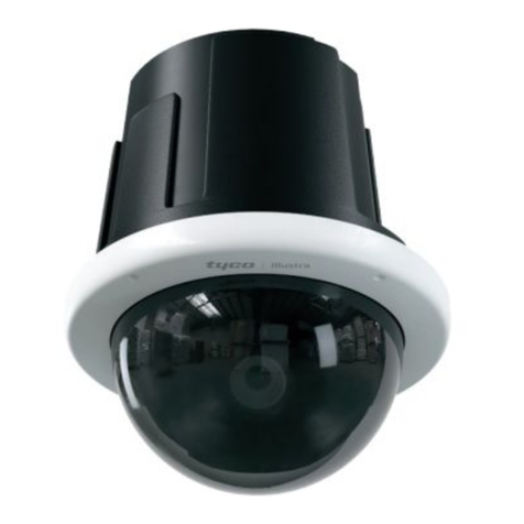
Johnson Controls Tyco Pro Gen2 User manual

Johnson Controls

Johnson Controls Tyco Pro Gen2 User manual

Johnson Controls TYCO Illustra Pro IPS02-P07-RT04 User manual

Johnson Controls

Johnson Controls TYCO Illustra Pro IPS02-P07-RT04 User manual

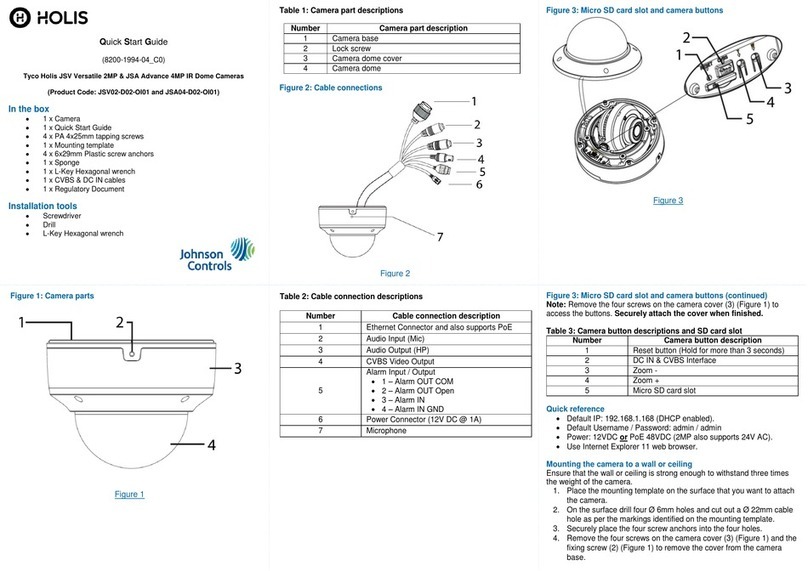
Johnson Controls Holis JSV02-D02-OI01 User manual

Johnson Controls

Johnson Controls Holis JSV02-D02-OI01 User manual

Johnson Controls Tyco Illustra Essentials Gen4 User manual

Johnson Controls

Johnson Controls Tyco Illustra Essentials Gen4 User manual

Johnson Controls tyco Illustra Pro User manual

Johnson Controls

Johnson Controls tyco Illustra Pro User manual

Johnson Controls Tyco Illustra Flex User manual

Johnson Controls

Johnson Controls Tyco Illustra Flex User manual

Johnson Controls Tyco Illustra User manual

Johnson Controls

Johnson Controls Tyco Illustra User manual

Johnson Controls Tyco Illustra Flex IFS03D1ICWTT Service manual

Johnson Controls

Johnson Controls Tyco Illustra Flex IFS03D1ICWTT Service manual

Johnson Controls Tyco Holis JSV User manual

Johnson Controls

Johnson Controls Tyco Holis JSV User manual

Johnson Controls Illustra Flex Gen 4 User manual

Johnson Controls

Johnson Controls Illustra Flex Gen 4 User manual

Johnson Controls tyco Illustra IBPN-M-IS-0 User manual

Johnson Controls

Johnson Controls tyco Illustra IBPN-M-IS-0 User manual

Johnson Controls Tyco Illustra Pro Gen4 User manual

Johnson Controls

Johnson Controls Tyco Illustra Pro Gen4 User manual

Johnson Controls Illustra PRO User manual

Johnson Controls

Johnson Controls Illustra PRO User manual

Popular Security Camera manuals by other brands

ALIBI ALI-NS4002R Quick installation guide

ALIBI

ALIBI ALI-NS4002R Quick installation guide

Night Owl C80XFR Series user manual

Night Owl

Night Owl C80XFR Series user manual

Vicon XX152-10-01 Installation & operating manual

Vicon

Vicon XX152-10-01 Installation & operating manual

Swann PRO-680 operating instructions

Swann

Swann PRO-680 operating instructions

JVC VN-H37U series Operation manual

JVC

JVC VN-H37U series Operation manual

ERA Protect 20275 quick start guide

ERA

ERA Protect 20275 quick start guide

Panasonic WV-X4173 BASIC INFORMATION

Panasonic

Panasonic WV-X4173 BASIC INFORMATION

Vivotek C Series Quick installation guide

Vivotek

Vivotek C Series Quick installation guide

Costar ARECONT VISION CONTERA installation manual

Costar

Costar ARECONT VISION CONTERA installation manual

Axis M5014 datasheet

Axis

Axis M5014 datasheet

JAI CV-M 9CL Operation manual

JAI

JAI CV-M 9CL Operation manual

SumoSecurity IP-CAM-726-A28P Setup instructions

SumoSecurity

SumoSecurity IP-CAM-726-A28P Setup instructions

VADDIO ClearVIEW 999-6990-000 Installation and user guide

VADDIO

VADDIO ClearVIEW 999-6990-000 Installation and user guide

D-Link DCS-7413 Technical specifications

D-Link

D-Link DCS-7413 Technical specifications

Lorex LW2110 Series instruction manual

Lorex

Lorex LW2110 Series instruction manual

D-Link DCS-5610 Quick installation guide

D-Link

D-Link DCS-5610 Quick installation guide

D-Link DCS-8600LHA1 user manual

D-Link

D-Link DCS-8600LHA1 user manual

Vitek Transcendent VTC-TNT4FLN-2 quick start guide

Vitek

Vitek Transcendent VTC-TNT4FLN-2 quick start guide

manuals.online logo
manuals.online logoBrands
  • About & Mission
  • Contact us
  • Privacy Policy
  • Terms and Conditions

Copyright 2025 Manuals.Online. All Rights Reserved.