Jorvet J0558X User manual

TOP LINE
ANESTHESIA SYSTEM
J0558X & J0558Z |USER MANUAL
The JorVet Top Line Anesthesia System pictured above shows
optional accessories (J0558Y Bain Block and J0744SV Concentrator).

CONTENTS
Top Line Anesthesia System Models
Intended Use
Unpacking/Included Items
Circuit Descriptions, Warnings, and Notes
Description of Controls/Features
Product Operation
Concentrator Kit Installation
Attaching Circuits
Gas Flow Chart
Routine Maintenance
Troubleshooting and Specications
Warranty and Service
03
04
05
06
07
08
09
10
11
12
13
Thank you for using our JorVet J0558X and J0558Z Anesthesia System.
We want you to get the most out of the machine and to have your experience
in using it proceed with ease. Detailed instructions are provided along with
the product’s description and features on how to correctly use it and take full
advantage of all operations and functions.

3
TOP LINE ANESTHESIA SYSTEM MODELS
J0558X
J0558Z
Shown with optional J0558Y Bain
Block and J0744SV Concentrator
IMPORTANT! VAPORIZER NOT INCLUDED FOR BOTH MODELS

4
INTENDED USE
UNPACKING/INCLUDED ITEMS
The JorVet Top Line Anesthesia System was designed for Veterinary Use Only. It is a lightweight,
durable, mobile system with 3” casters for maneuverability. The JorVet Top Line Anesthesia
System includes an incorporated toggle to switch between rebreathing and nonrebreathing
systems. This feature eliminates the need to remove the breathing circuits during use. There is a
monitor shelf as well as a middle shelf to provide more workspace and keep the patient’s vitals
and anesthesia controls in one area.
JorVet Top Line Anesthesia System Assembly
uH-Frame Stand, Mounting Plate Assembly and Rebreathing Head, Vaporizer Inlet and
Outlet Endcaps (Figure 1)
uHardware Packet (Not pictured)
u
10 Second Card w/chain
u
Black Absorber Canister Cover
u
4 – Top Shelf Bolts (1/4”-20 x 1/2” Flat)
u
4 – Connecting Bolts (1/4”-20 x 1/2” Button)
u
1 – Allen Wrench (5/32”)
u2 – Zip Ties
u1 – E-cylinder Wrench (Model J0558X Only)
uAssembly Quick Guide (Not pictured)
uUniversal F-Circuit with 3L Bag (Figure 4)
uNon-rebreathing Circuit (Figure 5)
Figure 1
Figure 4 – J0248F
Figure 5 – J0248G

5
CIRCUIT DESCRIPTIONS, WARNINGS, AND NOTES
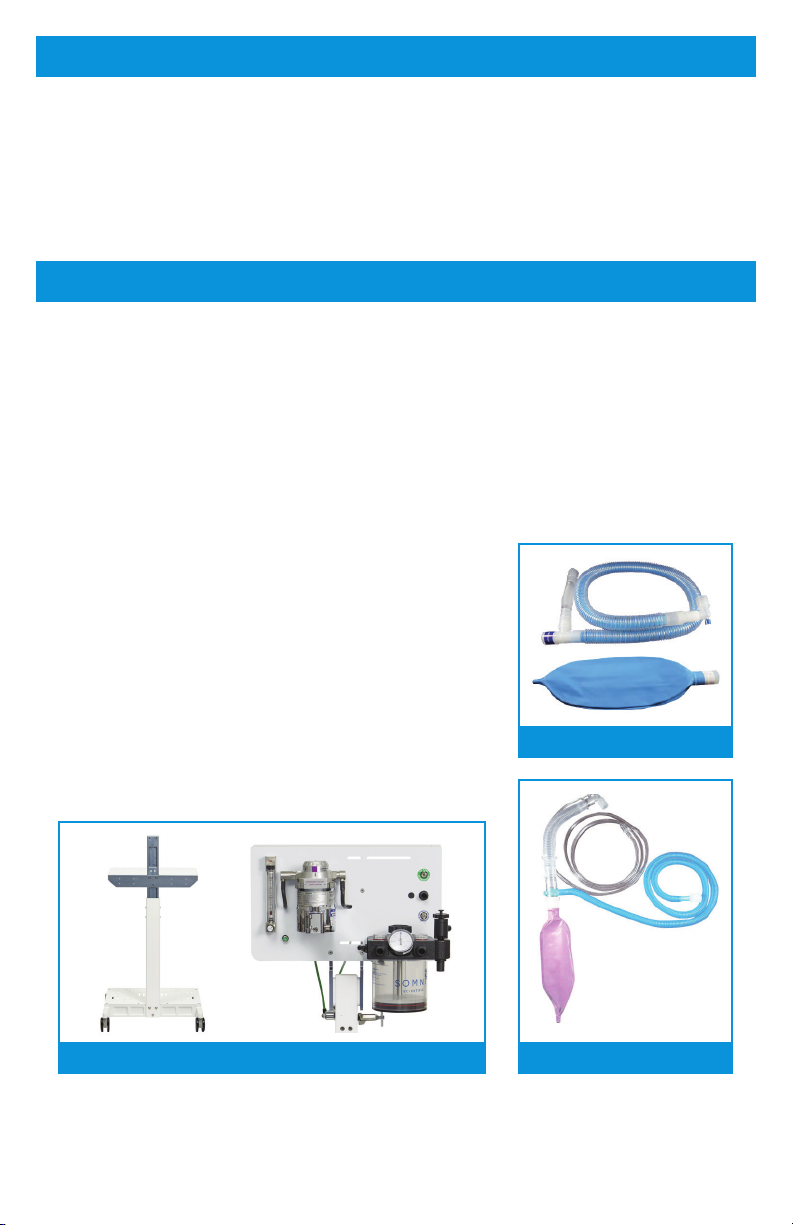
The F-Circuit is a rebreathing circuit for use
with animals that weigh approximately 15 lbs. (7kg) or more.
The Non-rebreathing Circuit is a circuit for use
with animals that weigh approximately 15 lbs. (7kg) or less.
WARNINGS
uOperator must read entire manual prior to operation and have proper training in
the use of inhalant anesthetic equipment. Failure to do so may harm the animal.
uDo not connect unregulated compressed carrier gas to the Top Line Anesthesia
System. Compressed oxygen, or another carrier gas, should be supplied at 50-55 psi.
uPop-off (APL) valve is closed for shipping. Completely open the pop-off valve prior to
use. The pop-off valve should be kept open during normal operation and only closed
when performing a leak check or using a ventilator.
uAs a patient safety feature, the oxygen ush will not work with a non-rebreathing circuit.
The oxygen ush is only piped to the rebreathing absorber.
uAlways operate inhalant anesthetic equipment with waste gas scavenging systems.
Failure to control waste anesthetic gas may cause harmful exposure to personnel.
uWhen using the oxygen concentrator, turn the anesthesia machine owmeter on to
allow ow. The concentrator alarm will sound if this step is not followed.
NOTE
uWhen using the oxygen concentrator with the J0558X model, the oxygen ush will not
operate without the E-cylinder turned on. The oxygen ush is piped to the e-cylinder
only.
uWhen using the oxygen concentrator, turn the concentrator ow to match the owrate
on the anesthesia machine.
uDo not overtighten the owmeter knob. When the oat is resting at the bottom of the
owmeter, the owmeter is off. Overtightening will damage the needle valve and result
in leakage.
uAnesthetic Vaporizer and carrier gas (oxygen) accessories are not included. Please
follow the installation guides for these products.

6
DESCRIPTION OF CONTROLS/FEATURES
1
23
6
5
7 7
8
9
10
11
14
15
16
12
13
4
Common Gas Outlet
Switch - O2Tank/02Concentrator
(J0558X Model Only)
Switch - Rebreathing/
Non-rebreathing
9
10
Pop-o (APL) Valve
11
Rebreathing Bag Port
Absorber Canister
12
13
Absorber Canister Knob
14
Manometer
15
16
Oxygen Flowmeter
Flush Valve
1
2
Accessory Mounting Area
3
Inhalation Port
Exhalation Port
4
5
Mounting Area for
E-cylinder Manifold
6
Vaporizer Endcaps -
Inlet and Outlet
7
Accessory Mounting Area
8

7
PRODUCT OPERATION
REFER TO PRODUCT INSTALLATION GUIDE FOR ILLUSTRATION
FOLLOW ALL STEPS ACCORDINGLY
uRemove all cartons from the main package.
uRemove the machine H-Frame base unit.
uUnpack and inspect remaining components for damage. Be sure to retain the mounting
hardware contained inside package.
uAttach middle shelf to center post using 3 bolts.
uAttach center post with middle shelf attached to H-frame base with 4 bolts.
uAttach mounting plate assembly to center pole with 4 bolts. Note: Two people
recommended for this step.
uAttach rebreathing head to mounting plate assembly using supplied bolts and allen
wrench.
uConnect black supply line to the hose barb on the left side of the rebreathing head.
Warning: Open pop-off valve prior to use.
uInstall anesthetic vaporizer onto frame with vaporizer spacer block positioned on the
front face of the mounting plate and tighten. Note: Two people recommended for this
step. Mounting hardware supplied with vaporizer.
uConnect the inlet and outlet endcaps using a push and twist action to provide a leak
free attachment. Note: This step can be performed prior to installing the vaporizer
onto the frame if needed.
uConnect oxygen (carrier gas) supply source to the DISS Male tting on the back of the
owmeter. Note: For Model J0558X see next page for Concentrator Kit installation.
uTurn the oxygen (carrier gas) supply on.
uConnect appropriate active or passive waste gas scavenging system to the 19mm
outlet of the pop-off valve.
uEnsure vaporizer has been lled per manufacturer’s instructions and is ready for use.
uFill absorber canister to line indicated on canister. Use supplied downtube cover (on
chain) when lling. Attach absorber canister to the rebreathing head and tighten.
Note: Absorbent not included.
uLeak test following instructions on 10 second pressure test card.

8
CONCENTRATOR KIT INSTALLATION – MODEL J0558X
Stud Hardware Installed on Base Plate
u4 – 3/8”-24 x 2” Hex Bolt
u8 – 3/8” x 24 Hex Nut
u12 – 3/8” SS Washer
u4 – 3/8” Cushioning Washer
In order as installed: Bolt, SS Washer, Base Plate, SS Washer, 2x Hex Nut, SS Washer,
Cushioning Washer.
FOLLOW ALL STEPS ACCORDINGLY
uUnpack concentrator and remove wheels by pulling away from (base) of concentrator.
uInstall stud hardware on base plate in correct holes based on where wheels were
located on concentrator.
uSet concentrator on studs sticking up from base plate. Note: Two people recommended
for this step.
uThe single E-cylinder manifold will be pre-installed on the middle support shelf. Ensure
the brass and black washer/seal is in place prior to installing the e-cylinder.
uAttach the two high pressure, small green tubes from the anesthesia machine to the
E-tank regulator by pushing the tubing into the ttings. Once resistance is felt, continue
to push the tubing slightly further to secure connection. Gently pull on tubing to test for
proper connection. Note: The E-cylinder must be turned on to operate the oxygen
ush.
uAttach low pressure, large green tubing from the anesthesia machine to the concentrator
by threading the green female tting onto the male tting on the concentrator.
uOptional: Use supplied cable tie to organize the green tubing.
WARNING
uWhen using the oxygen concentrator, ip the switch on the front of the anesthesia
machine to concentrator prior to turning the concentrator on.
uWhen using the oxygen concentrator, turn anesthesia machine owmeter on to allow
ow. The concentrator alarm will sound if this step is not followed.
NOTE
uWhen using the oxygen concentrator, turn the concentrator ow to match the owrate
on the anesthesia machine.

9
ATTACHING CIRCUITS
F-CIRCUIT ATTACHMENT
For use with animals that weigh
approximately 15 lbs. (7kg) or more.
uConnect the longer, single limb of the circuit to
the inhalation valve.
uConnect the shorter, corrugated tube to the
exhalation valve.
uConnect a rebreathing bag (appropriate to the
patient size) to the port located below the pop-
off valve.
uFlip the Rebreathing/Non-rebreathing switch to
Rebreathing when using this circuit. Note: It is
not necessary to remove the non-rebreathing
circuit.
NON-REBREATHING CIRCUIT ATTACHMENT
For use with animals that weigh
approximately 15 lbs. (7kg) or less.
uInsert the adapter on the end of the long, clear
tubing into the Common Gas Outlet (located
above the Rebreathing/Non-rebreathing switch).
uAttach the corrugated tubing to the waste gas
scavenging system.
uConrm the bag bleed valve/slide valve is open
on the non-rebreathing circuit.
uFlip the switch to non-rebreathing when using
the non-rebreathing circuit. It is not necessary to
remove the rebreathing circuit.
WARNING
uAs a patient safety feature, the oxygen ush
will not work with a non-rebreathing circuit. The
oxygen ush is only piped to the rebreathing
absorber.

10
GAS FLOW CHART
OXYGEN
(CARRIER GAS)
SUPPLY
REGULATOR
Compressed Tank, in-house
or Concentrator
*Not needed for
Concentrator
Regulated
Oxygen
(Carrier Gas)
Hose
Anesthetic Agent
and Oxygen
(Carrier Gas) Mixture
Flowmeter
0-4 LPM
Vaporizer
Common
Outlet

11
Daily Testing
Cleaning
uTurn the owmeter knob fully open and observe as the oat ascends and descends
freely. The oat should rest completely at the bottom when knob is turned off.
uInspect lines, connectors and accessories for wear prior to use.
uPerform a Leak Test (shown on bottom).
uUse a damp cloth to clean.
uDO NOT use alcohol.
uDO NOT spray cleaning agent directly onto the machine surface.
uDilute Chlorhexidine or similar cleaning and disinfecting agent can be used.
ROUTINE MAINTENANCE
BEFORE EACH USE, “LEAK TEST” THE MACHINE,
AND ALSO ENSURE THAT THE WASTE GASES HAVE
A CLEAR WAY THROUGH YOUR EVACUATION SYSTEM.
1
2
3
4
5
6
Close the pop-o valve and create a tight seal of the patient circuit
with your hand.
Push the oxygen ush button, or turn on oxygen ow meter, until
the bag is fully distended and/or manometer reads 30-40 cm of H2O
pressure.
Re-open the pop-o valve to your standard setting.
Squeeze the bag (with your hand still over the patient circuit) to ensure
the gases have a clear way out through your scavenging system.
Release the oxygen ush button and/or ensure the oxygen owmeter
is o; oat is at the bottom of the tube. Observe the manometer (or the
bag if your machine does not have a manometer) for 20-30 seconds.
The manometer needle should remain steady. If the manometer needle
drops, the bag deates, or if you hear a hissing sound, you have a leak.
Check hoses, bag, vaporizer inlet and outlet, any ttings or seals at the
top and/or bottom of your CO2absorbent container for leaks (a soapy
water solution can be used for leak test). When the pressure remains
constant, with the oxygen turned o, your machine can be considered
leak-free on the low-pressure side.

12
TROUBLESHOOTING
SPECIFICATIONS
PROBLEM CAUSE ANALYSIS SOLUTION
FLOWMETER WILL
NOT TURN OFF
Inspect needle valve for
wear. Check adjustments.
Replace needle valve
or make adjustments.
ANIMALS WILL NOT GO TO
SLEEP/STAY ASLEEP
1. Inspect system for leak
2. Inspect breathing circuit
and bag for leak or loose
connections.
3. Check active waste
gas system function/
attenuation.
4. Conrm vaporizer has
an adequate amount of
agent.
1. Tighten any loose
connections (vaporizer
endcaps, tubing
connections).
2. Replace breathing
circuit or bag. Fix loose
connections.
3. Ensure active waste
gas system function/
attenuation is working
properly
4. Fill vaporizer with correct
amount of agent.
FOR ASSISTANCE, CALL 1.800.525.5614
Weight 45 lbs./20.5 kg
Dimensions 21”W x 21”D x 53”H
(53mm x 53mm x 135mm)
Vaporizer Endcaps 23mm tapered
Flowmeter 0.2-4 LPM
Oxygen (Carrier Gas) Inlet DISS Male
Frame Aluminum

13
WARRANTY SERVICE
Limited Warranty
Jorgensen Laboratories warrants to the original purchaser that the products, not including
accessories, shall be free from defects in materials and workmanship under normal use, if
maintained in accordance with Jorgensen Laboratories’ guidelines and used according to its
labeling, for the period specied in the manual.
Warranty Period – 5 Years from the Invoiced Date of Purchase
THIS LIMITED WARRANTY, IS IN LIEU OF AND EXCLUDES ALL OTHER WARRANTIES
WHETHER EXPRESSED OR IMPLIED, BY OPERATION OF LAW OR OTHERWISE, INCLUDING
BUT NOT LIMITED TO, ANY IMPLIED WARRANTIES OF MERCHANTABILITY OR FITNESS
FOR A PARTICULAR PURPOSE.
This warranty is void if the product has been altered, misused, damaged by neglect or accident,
tampered with, not properly maintained, not installed in strict compliance with applicable
codes and ordinances, or repaired by persons not authorized by Jorgensen Laboratories. This
warranty does not cover normal wear and tear and maintenance items and specically excludes
accessory items and any other equipment used with the product.
Limitation of Remedies
Jorgensen Laboratories’ only obligation under this limited warranty is the repair or replacement
of the product. THIS IS THE EXCLUSIVE REMEDY. Jorgensen Laboratories shall not be liable
for and hereby disclaims any direct, incidental, consequential or special damages or delays,
including but not limited to loss of use, downtime, lost business, revenues and prots.
Warranty Procedure
To obtain warranty service, contact Jorgensen Laboratories:
Jorgensen Laboratories Inc. |1450 N. Van Buren Ave. |Loveland, CO 80538

Jorgensen Laboratories, Inc. |Loveland, CO 80538
Professional Veterinary Equipment Supplier
This manual suits for next models
1
Table of contents
Other Jorvet Medical Equipment manuals
Popular Medical Equipment manuals by other brands

Mortara Instrument
Mortara Instrument Ambulatory X-12 Operator's manual

Toomac
Toomac Juzo ACS Light Thigh Wrap Instructions for use and care

FujiFilm
FujiFilm SonoSite Edge User guide supplement

Revitalife
Revitalife CLOUD LUXURY THERAPEAUTIC SLEEP SYSTEM owner's manual

laerdal
laerdal VitalsBridge 100 Directions for use

dymax
dymax BlueWave 200 user guide