9
The Quality Connection
7. Precautions
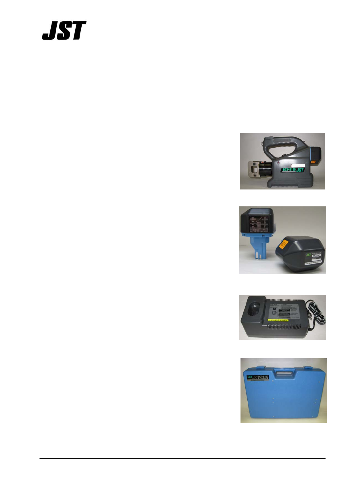
Crimping Tool
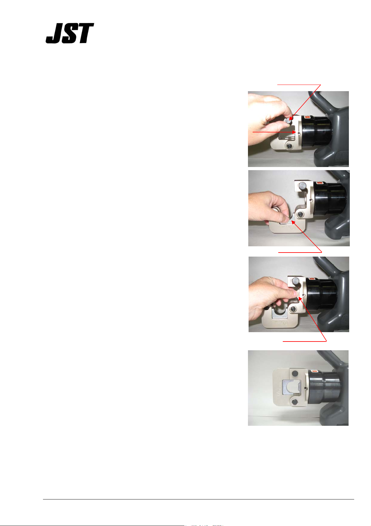
1. Be sure to select the appropriate dies for the terminal to be crimped.
2. Never operate the tool without dies mounted and a terminal being crimped.
3. If the tool is stored at a cold temperature for an extended time, it is advisable to return to
room temperature for 1 hour before using.
4. Avoid dropping the tool. Excessive shock may damage the hydraulic circuit causing the
tool to malfunction.
5. Keep the cylinder head and piston clean and free of debris. Solvent can be used on the
head but should not be used on the plastic body.
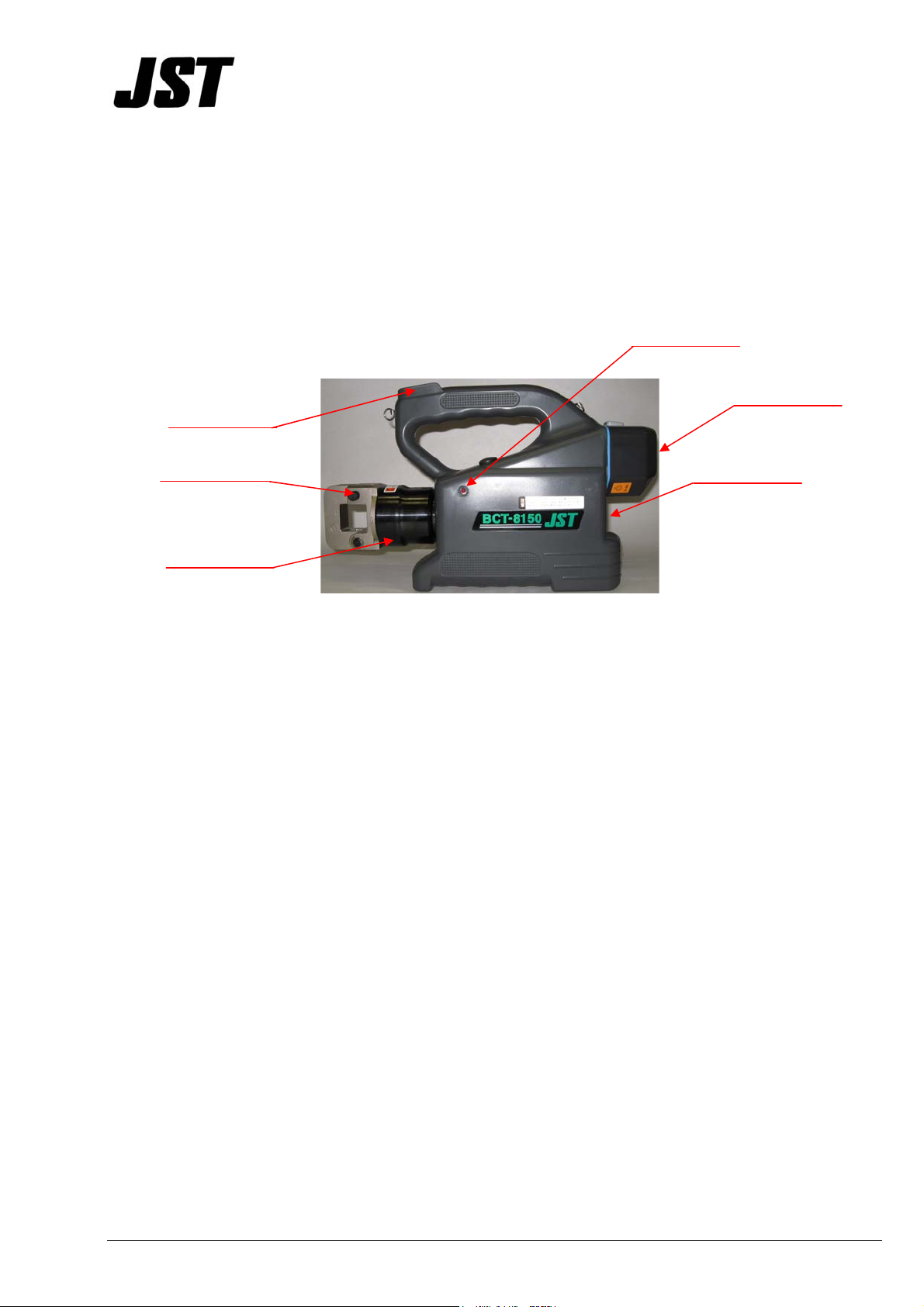
Battery Cartridge
1. Never short circuit the battery terminals.
2. Avoid getting water, oil, or solvent near the battery.
3. Never disassemble or modify the battery.
4. Avoid dropping the battery cartridge.
5. Never store the battery at above 60 degrees Celsius for a long period of time.
6. Replace the battery cartridge when the crimping cycles are reduced to half of the cycles
indicated in the estimated crimping cycles section.
7. Never dispose of the battery cartridge in a fire.
8. The battery cartridge self discharges over time. It is recommended to charge the battery at
least every 3 months if the tool is not regularly used.