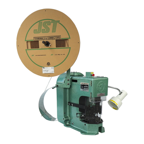
JST AP-K2 User manual

AP-K2 CRIMPING
MACHINE
OPERATION
MANUAL

H:\0 - Quality Documents\2 Department\Tech Serv\Application tooling\Presses\AP-K2\TS009-02 AP-K2 Operation Manual.doc
2
PREFACE
The AP-K2 semi-automatic crimping machine is easy to operate, and is suitable
for mass production of crimped harnesses with chain terminals.
Before using the AP-K2 please read this manual to ensure that you are familiar
with the features of the machine and the layout of the operating controls.
We recommend that you always keep this manual near the machine to use for
reference when required. This manual also contains information on
maintenance, fault-finding and adjustment of the crimping machine and its
associated tooling.

H:\0 - Quality Documents\2 Department\Tech Serv\Application tooling\Presses\AP-K2\TS009-02 AP-K2 Operation Manual.doc
3
CONTENTS
1.
Specifications
Page 4
1-1. Crimping machine specifications
Page 4
1-2. Applicator Specifications
Page 4
2.
Installing the machine
Page 5
2-1. Machine Installation
Page 5
3.
Machine preparation
Page 6
3-1. Mounting of the Reel hanger
Page 6
3-2. Mounting of the Applicator
Page 6
Prevention of tooling damage
Page 7
Prevention of terminal damage
Page 8
3-3. Mounting the Terminal reel
Page 9
3-4. Setting the counter
Page 10
3-5. Mounting the Safety guard
Page 10
4.
Operation
Page 11
4-1. Manual operation
Page 11
4-2. Inspection before operation
Page 12
4-3. Operation under power
Page 12
5.
Applicator
Page 13
5-1. Terminal feed position adjustment
Page 13
5-2. Bell mouth adjustment
Page 14
5-3. Feed-finger travel adjustment
Page 15
5-4. Crimp height adjustment
Page 15
5-5. Die part replacement
Page 16
5-6. Lubrication of Applicator
Page 16
6.
Maintenance
Page 17
6-1. Lubrication
Page 17
6-2. Inspection and repair
Page 19
6-3. Positioning the solenoid bracket
Page 20
7.
Fault finding
Page 21
Electrical circuit diagram
Page 25
8.
Exploded views and parts list
AP-K2 Crimping machine exploded view
Page 26
MK-L Applicator
Page 28
MKS-L Applicator
Page 30
MKF-L Applicator
Page 32
MKS-LS Applicator
Page 34

H:\0 - Quality Documents\2 Department\Tech Serv\Application tooling\Presses\AP-K2\TS009-02 AP-K2 Operation Manual.doc
4
1. SPECIFICATIONS
The crimping machine is composed of the
crimping press and an applicator.
There are two basic types of applicators
(a total of four models).
1.1 Crimping Machine Specifications
1.2 Applicator specifications
Model no. MK-L (for-end feeding terminals)
º Weight 6.8 Kg
º Feed pitch 30mm max.
º Crimp height adjustment: Dial type
Model no. MKF-L (for-end feeding flag terminals)
º Weight 6.8 Kg
º Feed pitch 30mm max.
º Crimp height adjustment: Dial type
Models MK-L and MKF-L for end feeding
terminals, and models MKS-L and MKS-LS for
side feeding terminals. The crimping machine
utilises a quick-change system thus allowing quick
changeover times.
Model no: AP-K2
º External dimensions: 280mm Wide x
480mm Long x 560mm High
º Weight: 95 Kg
º Power supply: 220/240V AC single phase
50/60 Hz
º Power consumption: 680VA
º Crimping force: 1500 Kg
º Ram stroke: 30mm
º Ram speed: 260 strokes per minute
(60 Hz), and 220 strokes per minute
(50 Hz)
º Closed height: 160.0 mm ± 0.01 at B.D.C
Model no. MKS-L (for side-feeding terminals)
º Weight 6.4 Kg
º Feed pitch 30mm max.
º Crimp height adjustment: Dial type
Model no. MKS-LS (for side feeding terminals)
º Weight 4.5 Kg
º Feed pitch 30mm max.
º Crimp height adjustment: Dial type

H:\0 - Quality Documents\2 Department\Tech Serv\Application tooling\Presses\AP-K2\TS009-02 AP-K2 Operation Manual.doc
5
2. INSTALLING THE MACHINE
2.1 Installation
Mount the crimping machine on a solid foundation,
place a rubber mat between the machine and
foundation to reduce vibration and stabilise the
machine.
The diagram to the left illustrates the footprint
dimensions of the machine. Secure the machine to
the foundation with four M8 bolts.
The machine should be mounted so that the
crimping dies are at the approximate eye level of a
seated operator.
CAUTION
Ensure that the belt cover of the crimping machine
does not overhang the edge of the mounting
surface.

H:\0 - Quality Documents\2 Department\Tech Serv\Application tooling\Presses\AP-K2\TS009-02 AP-K2 Operation Manual.doc
6
3. MACHINE PREPARATION
3.1 Mounting the Reel hanger
Due to packing considerations, when you receive the machine the Reel hanger is not mounted on the
machine. Assemble the Reel hanger then mount it on the machine as illustrated below.
Step 1
Assemble the Reel hanger as shown in the photo
below.
Step 2
Mount the Reel hanger on the Crimping machine.
3.2 Mounting the Applicator
Step 1
Loosen bolts A and B with a 5mm hexagon
wrench supplied with the tool-kit.
Step 2
Remove the protective rubber collar from under the
dials on the applicator ram.
Step 3
CAUTION
Ensure that the shank is correctly located in the
ram. There is a danger of major tooling damage if
the tooling is not located correctly (as in the
photograph below).
Step 4
Securely fasten the clamps with the 5mm hexagon
key, and visually check that the tooling is mounted
correctly.

H:\0 - Quality Documents\2 Department\Tech Serv\Application tooling\Presses\AP-K2\TS009-02 AP-K2 Operation Manual.doc
7
PREVENTION OF TOOLING DAMAGE.
1.
Place the rubber collar under the
ram head as shown in picture 1.
IMPORTANT.
Repeat this procedure every time
you remove an applicator from
the press.
Picture 1.
2.
DO NOT leave the applicator
without the rubber collar attached,
as shown in picture 2.
Picture 3.
Picture 2
.
3.
Picture 3, is a zoomed in view of
the punch and anvil when the
rubber collar is left off.
The two circled points are the
points of contact where the
damage will be caused.
Picture 3.

H:\0 - Quality Documents\2 Department\Tech Serv\Application tooling\Presses\AP-K2\TS009-02 AP-K2 Operation Manual.doc
8
PREVENTION OF TERMINAL DAMAGE.
1. Mount reel on reel holder attached to the
side of the press, as shown.
2. Adjust the collar; ensure that the collar is
adjusted so there is a light drag on the reel
prior to untying the reel.
3. Terminals are tied with wire, do not untie
before collar is fitted as the windings will
become loose, always re-tie after each
production run.
4. Make sure the reels are stored up on end in
the original box, do not lay the terminals on their
side as they can drop and get tangled.
CORRECT.
INCORRECT.

H:\0 - Quality Documents\2 Department\Tech Serv\Application tooling\Presses\AP-K2\TS009-02 AP-K2 Operation Manual.doc
9
3.3 Mounting the Terminal reel
Step 1
Mount the terminal reel to the reel hanger so
that the terminal barrels are facing the reel
guide.
Step 2
Feed the terminals through the terminal guide.
Mounting the MK-L applicator
Step 3
Push down the tension lever and engage the
hook with the feed plate so that the pressure
pad rises. Feed the terminal strip between the
guide rails.
Step 4
Place the first terminal at the correct crimping
position. Release the hook from the feed plate to
allow the pressure pad to apply pressure on the
strip.
Mounting the MKS-L applicator
Step 3
Rotate the wing bolt clockwise to raise the
pressure plate. Feed the terminal strip between
the guide rails.
Step 4
Place the first terminal in position so that the
terminal is centralised over the anvil. Rotate the
wing bolt counter- clockwise to lower the pressure
plate so that pressure is applied to the terminal.

H:\0 - Quality Documents\2 Department\Tech Serv\Application tooling\Presses\AP-K2\TS009-02 AP-K2 Operation Manual.doc
10
3-4. Setting the counter
The counter (5 digits) helps you to count the
number of crimped terminals processed.
Press the reset button to reset the counter to
zero.
3-5. Mounting the safety guard
There are many types of safety guards available, please consult JST for details.
A RELEVANT SET OF SAFETY GUARDS IS ALWAYS DESPATCHED WITH THE MACHINE

H:\0 - Quality Documents\2 Department\Tech Serv\Application tooling\Presses\AP-K2\TS009-02 AP-K2 Operation Manual.doc
11
4. OPERATION
WARNING
Disconnect the press from the power
supply before operating by hand.
Operations by hand whilst guards are
removed must only be performed by
authorised competent persons.
4.1 Manual Operation
CAUTION
When using an applicator for the first time
after fitting it in the press, or whenever a die-
part is replaced or the applicator is adjusted,
ensure that the press is manually cycled at
least one revolution. This is a very important
operation to ensure that the terminals are
crimped correctly and it also allows a degree
of ‘feel’ through the crank handle which
prevents major tooling damage from
occurring if the die-parts have been installed
incorrectly.
Step 1
Turn off and disconnect the power.
Step 2
Manually operate the solenoid by pushing the
clutch lever in a downward direction until the
clutch ‘clicks’.
Step 3
Place the hand-crank supplied in the press
tool-kit on the end of the main shaft and
rotate in a counter-clockwise direction to
manually cycle the press through one
revolution. The ram moves up and down one
stroke and crimps the terminal.
Step 4
Remove the hand-crank and close the belt
cover.
Step 5
CAUTION: Ensure that hand-crank is rotated
through one complete revolution (until it
physically stops). If the press is left partway
through a cycle it will try to complete the cycle
when the motor is turned on and this action
could result in damage being caused to the
tooling.

H:\0 - Quality Documents\2 Department\Tech Serv\Application tooling\Presses\AP-K2\TS009-02 AP-K2 Operation Manual.doc
12
4.2 Inspection before operation
IMPORTANT
Ensure that the hand crank has been removed before commencing.
Ensure the correct fitting of the guards.
4-3. Operation under power
Step 1
Connect the power supply cable and the foot-
switch cable to the control box using the screw in
connectors. Connect the power supply cable to the
mains supply and switch on the press.
CAUTION
Ensure that the power supply cable is routed from
the press safely and does not become trapped or
chafed by any part of the crimping machine.
Step 2
Turn ON the light by the rotary switch as shown
below.
Step 3
Turn the power switch ON; you will hear the fly-wheel
start to turn.
Step 4
Position a wire over the terminal and press the foot-
switch once to activate it. The terminal is crimped and
the next terminal is indexed along over the anvils
ready for the next operation.
CAUTION If any problems occur during operations, immediately press the Power Off push-button and investigate the reason If the problem
requires the removal of safety guards, contact a person authorised to remove the guards. ON NO ACCOUNT REMOVE SAFETY GUARDS
IF YOU ARE NOT AUTHORISED TO DO SO.

H:\0 - Quality Documents\2 Department\Tech Serv\Application tooling\Presses\AP-K2\TS009-02 AP-K2 Operation Manual.doc
13
6. APPLICATOR ADJUSTMENT
5.1 Terminal Feed Position Adjustment.
CAUTION
The following adjustments require the removal of the safety guards
and must only be carried out by authorised competent persons.
There is a risk of serious crushing injury in tooling exposed by the
removal of the safety guards. Ensure that fingers are kept away
from the moving parts of the applicator.
When using the MK-L Applicator
Adjust the terminal feed position to adjust the terminal crimping position.
Before making this adjustment be sure that the applicator is mounted in
the crimping machine correctly and the press ram is at Top Dead Centre.
Loosen the 5mm cap head socket screw and the knurled collar using a
small length of silver steel or similar, as indicated on the photograph.
With the aid of the silver steel or a flat-ended screwdriver rotate the
adjustment shaft so that the feed-finger places the terminal in the correct
position for crimping.
Rotate the shaft counter-clockwise to move the terminal forward, and
clock-wise to move it backwards.
When the adjustments are completed, tighten the knurled collar first
followed by the cap screw.
Rotate the press through one revolution manually (see page 10), and
check the resultant crimped terminal. If the appearance of the terminal is
not correct repeat the above adjustment operation and check again.
When a satisfactory result is achieved, replace the
guards, connect the crimping machine to the power
supply and recommence the crimping operation.
When using the MKS-L Applicator
Adjust the terminal feed position to adjust the terminal crimping position.
Before making this adjustment be sure that the applicator is mounted in
the crimping machine correctly and the press ram is at Top Dead Centre.
To position a terminal at the centre of the die, follow the procedure
below.
Loosen the 5mm cap head socket screw and the knurled collar using a
small length of silver steel or similar, as indicated on the photograph.
With the aid of the silver steel or a flat-ended screwdriver rotate the
adjustment shaft so that the feed-finger places the terminal in the correct
position for crimping.
Rotate the shaft counter-clockwise to move the terminal to the right
(forwards), and clock-wise to move it to the left (backwards).
When the adjustments are completed, tighten the knurled collar first
followed by the cap screw.
Rotate the press through one revolution manually (see page 10), and
check the resultant crimped terminal. If the appearance of the terminal is
not correct repeat the above adjustment operation and check again.
When a satisfactory result is achieved, replace the
guards, connect the crimping machine to the power
supply and recommence the crimping operation.
SCREW
COLLAR

H:\0 - Quality Documents\2 Department\Tech Serv\Application tooling\Presses\AP-K2\TS009-02 AP-K2 Operation Manual.doc
14
5.2 Bell Mouth Adjustment
When using the MK-L Applicator
Adjust the terminal feed position with reference to the bell-
mouth position. Refer to section 6.1
When using the MKS-L Applicator (old type)
Move the entire feed-plate to obtain the desired bell-mouth
crimp. First, loosen the feed-finger retaining screw in the
feed-finger holder. Next, loosen the two cap head socket
screws in the slots on the base of the applicator (see
photograph).
With the aid of a flat ended screwdriver, rotate the adjusting
screw in the front of the adjustment carriage, turn the screw
clockwise to increase the bell-mouth (move the guide rails
towards the front of the press), and counter-clockwise to
decrease the bell-mouth (move the guide rails towards the
back of the press).
Re-tighten the adjustment screws on the base of the
applicator, centralise the feed-finger in the slot in the guide
rail and tighten the screw.
Check the bell-mouth on the resultant crimp and re-adjust if
necessary.
When using the MKS-L Applicator (new type)
Move the entire feed-plate to obtain the desired bell-mouth
crimp. First, loosen the feed-finger retaining screw in the
feed-finger holder. Next, loosen the two hexagon-headed
bolts situated on the front of the adjustment carriage just
above the top surface of the applicator base-plate.
With the aid of a 5mm hexagon key, rotate the screw in the
front of the adjustment carriage, turn the screw clock-wise to
decrease the bell-mouth (move the guide rails towards the
back of the press), and counter-clockwise to increase the
bell-mouth (move the guide rails towards the front of the
press).
Re-tighten the adjustment bolts, centralise the feed-finger in
the slot in the guide rail and tighten the screw.
Check the resultant crimp and re-adjust if necessary.
There is a crimping manual available from the JST Technical
Department detailing the points to inspect on a crimped
terminal to achieve results as per our specifications.
A copy is issued with every AP-K2N Crimping machine
supplied to a customer but please contact JST if you require
further copies.
Slot-head adjustment screws
Feed-finger screw Adjustment screw
Hexagon nuts
Adjustment screw

H:\0 - Quality Documents\2 Department\Tech Serv\Application tooling\Presses\AP-K2\TS009-02 AP-K2 Operation Manual.doc
15
5.3 Feed-finger travel adjustment
Applicators are assembled and adjusted prior to despatch from JST
and will not require adjustment by customers. Please contact JST
Technical Services Department if you consider there is a problem
with the Pitch setting adjustment.
5.4 Crimp Height adjustment
The applicator has two dials to adjust the insulation and wire crimp-
height. The upper dial, marked with letters
A - H, is for the wire (conductor), crimp-height.
The lower dial, marked with numbers 1 - 8, is for the
insulation crimp height.
JST do not advise pad settings for wire sizes, as is the practice of
some manufacturers.
We believe that the best method to adopt is to specify crimp-heights
and adjust the dials until the desired crimp-height is achieved.
º Wire crimp-height (conductor) adjustment.
Setting the upper dial to graduation A produces the
tightest crimp-height (lowest), and graduation H the
least tight (highest). The crimp height alters by
approximately 0.05mm per graduation, so a total
range of adjustment of 0.40mm is attainable.
º Insulation crimp-height adjustment.
Setting the lower dial to graduation 1 produces the
tightest crimp-height (lowest), and graduation 8
the least tight (highest). The crimp-height alters by
approximately 0.10mm per graduation, so a total
range of 0.80mm is attainable.
We do not state insulation crimp-heights due to the
large variation of insulation types available. The
insulation should be set as per instructed in the JST
Crimping Manual supplied with the AP-K2N crimping
machine. If you require further copies, please contact
the JST Technical Services Department.
CAUTION
When initially installing the applicator in the press, ensure that
the dials are set at H - 8 to avoid the possibility of tooling
damage.
Always check the crimp-height of the terminal by use of a Crimp-
height Micrometer because they are designed specifically for the
purpose and indicate the true crimp-height. If you require details for
the supply of a crimp-height micrometer please contact JST
Technical Services Department.
If the applicator is not capable of achieving the desired crimp-height
by adjusting the dials, please contact the JST Technical Services
Department, because there is a range of blocks available to alter
the range of crimp heights available. If you specify the blocks
currently installed in your applicator (see ‘Exploded view’ supplied
with applicator), we can advise you of the part no of the
replacement blocks necessary to achieve the desired crimp-height.
Do not adjust the crimp-height by altering the shut-height of the AP-
K2N press, because it is factory set and should only require
occasional adjustment when serviced by the JST Service Engineer.
TOP DIAL- Conductor height
BOTTOM DIAL- Insulation height

H:\0 - Quality Documents\2 Department\Tech Serv\Application tooling\Presses\AP-K2\TS009-02 AP-K2 Operation Manual.doc
16
5-5. Die Part Replacement
The crimping dies are consumable parts. When a die part
becomes worn and requires replacement, check the part
number engraved on the die part, or consult the ‘exploded
view’ drawing supplied with every applicator and order a
new part from JST technical Services Department.
If you consider that the replacement process is too difficult,
or the tooling has sustained damage, please contact JST
to either send back the tooling for repair or alternatively a
JST Service Engineer can visit your company to repair the
tool on site.
5-6. Lubrication of Applicator
Periodically lubricate the surfaces indicated on the
photographs with grease. A general purpose grease
obtainable from Garages or car accessory shops is suitable.
Remove the ram from the applicator body and apply the
grease to the cam surface.
Apply grease to the surface of the cam-roller.
Apply grease to the four faces of the applicator ram.
CAUTION
Apply grease sparingly because excess grease attracts
dirt and scrap insulation etc.
CAM
CAM-ROLLER
APPLY GREASE HERE

H:\0 - Quality Documents\2 Department\Tech Serv\Application tooling\Presses\AP-K2\TS009-02 AP-K2 Operation Manual.doc
17
6. CRIMPING MACHINE
MAINTENANCE
CAUTION
Disconnect the Power Cable from the
mains supply before carrying out any
maintenance operations on the Crimping
Press.
6-1. Lubrication
MAIN SHAFT BEARING
Lightly grease the main-shaft bearing once a year using
a general purpose grease, eg Castrol LM.
RAM SECTION
Remove the cap head socket screws from the ram cover
and add a few drops of machine oil to the felt pads in the
three oiling holes once a week.
CLUTCH SECTION
Remove the cap head socket screws from the belt-cover
catch and open the cover.
Add a few drops of oil to the oiling points indicated on the
photograph.
NOTE: The frequency of lubrication is dependent on
the use of the machine. Do not apply excessive
lubrication because the oil may drip through onto
the applicator
and contaminate the terminals.
ROLLER CLUTCH
Step 1
Slowly rotate the fly-wheel whilst pulling the V-belts to the
side to remove them.
CAUTION
ENSURE THAT FINGERS DO NOT BECOME
TRAPPED BETWEEN THE V-BELT AND THE
FLY-WHEEL
Step 2
With the aid of a pair of internal circlip pliers, remove the
circlip retaining the fly-wheel.
MAIN SHAFT BEARING GREASING LOCATION
RAM SECTION OILING LOCATIONS
CLUTCH SECTION OILING LOCATIONS

H:\0 - Quality Documents\2 Department\Tech Serv\Application tooling\Presses\AP-K2\TS009-02 AP-K2 Operation Manual.doc
18
Step 3
Firmly grip the fly-wheel on both sides and pull off
the end of the shaft. There are seven ‘stick rollers’
inside the clutch and they may fall out when the
fly-wheel is pulled off the shaft, so take care not to
lose any.
Step 4
Remove any traces of old grease from all
components of the clutch mechanism and
sparingly lubricate all the clutch components with
fresh grease.
Specified Grease: Multemp PS no.1 manufac-
tured by Kyodo Yushi Co Ltd.
Do not use general purpose grease because
the clutch will not function correctly.
Contact JST Technical Services Department
for details of grease stockists.
Step 5
Assemble the clutch ensuring that the clutch lever
is engaged correctly with the clutch cam, as in
photo A.
If the clutch is assembled as in photo B, it will not
be possible to re-mount the flywheel onto the
shaft.
PHOTO A
PHOTO B

H:\0 - Quality Documents\2 Department\Tech Serv\Application tooling\Presses\AP-K2\TS009-02 AP-K2 Operation Manual.doc
19
6-2. Inspection and Repair
RAM STABILITY
Approximately every six months physically check that
the ram is not loose.
To check the ram, remove the screws from the catch
and open the cover.
Grip the ram firmly and try to move the ram from side to
side. It is also possible to detect whether the ram is
loose by the noise it makes when crimping, and also
the measured crimp height of the terminal may become
unstable.
º Adjustment Procedure
Step 1
Remove the two dome-nuts from the side wall of the
ram.
Step 2
Loosen the three cap head screws on the right hand
side of the adjustable ram guide.
Step 3
Fasten the grub screws on the ram guide finger-tight so
that you can manually move the ram up and down by
hand, but it does not drop under its own weight.
Next, check that the ram does not wobble and that it
moves smoothly.
Step 4
Make a final check that the ram is stable and the
screws are secure. Replace cap head screws in ram
cover.

H:\0 - Quality Documents\2 Department\Tech Serv\Application tooling\Presses\AP-K2\TS009-02 AP-K2 Operation Manual.doc
20
6.3 Positioning of the Solenoid Bracket
Once a year remove the cap head screw from the
catch on the belt cover and open the cover.
Check that the clearance is correct as shown on the
photograph.
The clearance should be 10-11mm, if it varies from this
dimension adjust the bracket in the following manner:-
Loosen the two cap head screws holding the bracket
to the press casting and move the solenoid up or down
until the correct clearance is obtained.
Tighten the cap head screws on the retaining bracket,
close the belt cover and replace the socket screws in the
bracket.
Clearance 10 - 11mm
Table of contents
Other JST Crimping Tools manuals
Popular Crimping Tools manuals by other brands

Tyco Electronics
Tyco Electronics 408-10050 instruction sheet

molex
molex CR60927A Specification sheet

HRS
HRS HT601/TM21P-88P operating instructions

Tyco Electronics
Tyco Electronics AUTOPRESS C120 Technical handbook

molex
molex 57022 Series operating manual

TE Connectivity
TE Connectivity PRO-CRIMPER III instruction sheet

Stanley
Stanley DUBUIS KW Hydraulik BPL031 instruction manual

Ilsco
Ilsco TASKMASTER TB-6DF1000-P instruction manual

LAPP
LAPP EPIC 11148001 EPIC 11148004 operating instructions

molex
molex 207129 Series Specification sheet

Samtec
Samtec CAT-HT-169-2024-11 quick start guide

haupa
haupa SMART-LINE SH-6 instruction manual