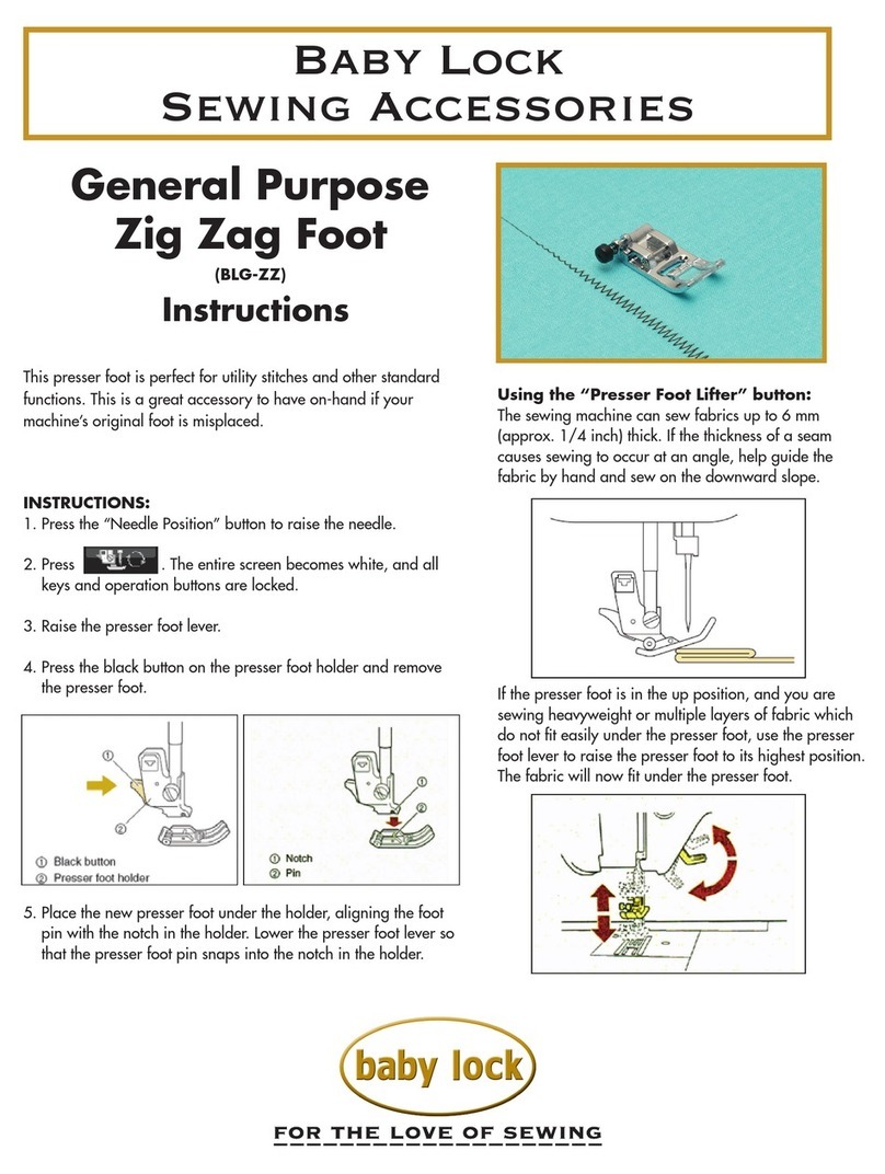
JUKI AE-9 User manual

Copyright C2002-2010 JUKI CORPORATION
• 本書の内容を無断で転載、複写することを禁止します。
• All rights reserved throughout the world.
この製品の使い方について不明な点がありましたらお求めの販売店又は当社営業所にお問い合わせください。
※この取扱説明書は仕様改良のため予告なく変更する事があります。
Please do not hesitate to contact our distributors or agents in your area for further information when necessary.
*
The description covered in this instruction manual is subject to change for improvement of the
commodity without notice.
10 · 11 Printed in Japan
INDUSTRIAL SEWING MACHINE DIVISION
2-11-1, TSURUMAKI, TAMA-SHI,
TOKYO, 206-8551, JAPAN
PHONE : (81)42-357-2371
FAX : (81)42-357-2274
http://www.juki.com
工業用ミシン事業部
〒 206-8551東京都多摩市鶴牧 2-11-1
TEL.
042-357-2371(ダイヤルイン)
FAX.
042-357-2274
http://www.juki.co.jp
No.04
29345204
R
取扱説明書
INSTRUCTION MANUAL
AE-9 / AE-12 /
AE-16 / AE-17
注意
本取扱説明書は、AE-9/AE-12/AE-16/AE-17 についての説明書です。本製品を LU-
2200N シリーズに取り付けて使用される際は、事前に LU-2200N シリーズの取扱説明書
の「安全についての注意事項」を読み、十分理解の上でご使用ください。
なお、AE-9/AE-12/AE-16/AE-17 を強調するため、LU-2200N シリーズのイラストは
簡略化されています。従って、安全装置のイラストも一部省略しております。
CAUTION
This Instruction Manual is intended for the AE-9, AE-12, AE-16 and AE-17. Read and fully
understand the instructions given under “IMPORTANT SAFETY INSTRUCTIONS” in the
Instruction Manual the LU-2200N series before putting the machine into service when this
device is installed to the LU-2200N series.
In addition, to emphasize the AE-9, AE-12, AE-16 and AE-17, some illustrations of the LU-
2200N series are simplified. Also, illustrations of the safety devices are partially omitted.
安全に使用していただくために使用前に、必ずこの取扱説明書をお読みください。
また、いつでもすぐに読めるように、この取扱説明書を保管してください。
Read safety instructions carefully and understand them before using.
Retain this Instruction Manual for future reference.
下糸残量検知装置
Bobbin Thread Remaining Amount Detecting Device

目次
!. 仕様....................................................................................................................1
@. セットアップ.....................................................................................................2
[1]AE-9/AE-16......................................................................................................................2
1.チューブ支えの取り付け...............................................................................................................2
2.センサ取付台の仮止め...................................................................................................................2
3.窓板の取り外し...............................................................................................................................3
4.ファイバーセンサの取り付け.......................................................................................................3
5.エアーチューブの配管...................................................................................................................5
6.窓板の取り付け...............................................................................................................................6
[2]AE-12/AE-17...................................................................................................................7
1.固定メス台ストッパーの取り外し................................................................................................7
2.窓板の取り外し...............................................................................................................................8
3.ファイバーセンサの取り付け.......................................................................................................9
4.エアーチューブの配管................................................................................................................11
5.窓板の取り付け............................................................................................................................12
[3]電磁弁の取り付け.............................................................................................................12
[4]センサアンプ・検知スイッチの取り付け......................................................................13
1.センサアンプの取り付け............................................................................................................13
2. 検知スイッチの取り付け............................................................................................................17
3.コードの配線...............................................................................................................................18
#. 感度調整.........................................................................................................20
1.センサアンプの機能の確認........................................................................................................20
2. センサアンプの感度調整値確認.................................................................................................21
3.ファイバーセンサの位置調整....................................................................................................22
4.エアーノズルの位置確認 (AE-9/AE-16)...............................................................................24
$. 動作と設定.....................................................................................................25
1.動作...............................................................................................................................................25
2.設定...............................................................................................................................................26
%. ボビンへの糸の巻き方..................................................................................28
^. 装置における現象と原因・確認又は対策...................................................29
&. 各コードの配線表..........................................................................................30
–32 –
(3) 電磁弁コード /Solenoid valve cord
(4)
電磁弁中継コード (SC-510 で使用 )/Solenoid valve connecting cord (to be used with SC-510)
CN124-1
CN124-1
1
2
3
4
CN7
1
2
2
1
CN7
線色 終了点 備考
赤 CN7-2 + 24 V
黒 CN7-1 エアーブロー(−)
Color of cord Ending point Remarks
Red CN7-2 +24V
Black CN7-1 Air blow( – )
線色 開始点 終了点 備考
白 CN7-2 CN124-1-1 + 12 V
黒 CN7-1 CN124-1-2 OUT
Color of cord Starting point Ending point Remarks
White CN7-2 CN124-1-1 +12V
Black CN7-1 CN124-1-2 OUT
(4)AE 中継コード (SC-922 で使用 )/AE junction cord (to be used with SC-922)
SC-510 用 /SC-922 用/For use with SC-510/SC-922
線色 開始点 終了点 備考
黒 CN103-1 CN51-4 AESW
白 CN103-2 CN51-15 AESWLED
緑 CN103-3 CN51-1 0V
赤 CN103-4 CN51-12 +24V
黄 CN104-2 CN51-5 AESENSOR1
茶 CN104-3 CN51-1 0V
青 CN104-5 CN51-6 AESENSOR2
黒 CN7-1 CN51-16 AEAIRBLOW
白 CN7-2 CN51-12 +24V
Color of cord Starting point Ending point Remarks
Black CN103-1 CN51-4 AESW
White CN103-2 CN51-15 AESW LED
Green CN103-3 CN51-1 0V
Red CN103-4 CN51-12 +24V
Yellow CN104-2 CN51-5 AE SENSOR1
Brown CN104-3 CN51-1 0V
Blue CN104-5 CN51-6 AE SENSOR2
Black CN7-1 CN51-16 AE AIR BLOW
White CN7-2 CN51-12 +24V
CN104
4 3
2 1
CN103
CN7
4 3
2 1
2
1
CN51
12 22
1 11
–31 –
終了点 備考
CN123-1 + 12 V
CN123-2 OUT
CN123-4 0V
(2) センサアンプコード /Sensor amplifier cord
線色 開始点
茶
黒 センサアンプ
青
Color of cord Starting point
Brown
Black
Blue
Ending point Remarks
CN123-1 +12V
CN123-2 OUT
CN123-4 0V
Sensor
Amplifier
CN123
CN123-1/-2
1
2
3
4
※2 本針頭部のときは、同じセンサアンプを 2 ケ使用します。
SC-510 用 (1 本針 /2 本針 )/For use with SC-510 (for 1-needle/2-needle machine head)
SC-922 用 (1 本針用 )/For use with SC-922 (for 1-needle machine head)
終了点 備考
CN104-1 + 24 V
CN104-2 OUT
CN104-3 0V
線色 開始点
茶
黒 センサアンプ
青
Color of cord Starting point
Brown
Black
Blue
Ending point Remarks
CN104-1 +24V
CN104-2 OUT
CN104-3 0V
Sensor
Amplifier
SC-922 用 (2 本針用 )/For use with SC-922 (for 2-needle machine head)
CN104
4 6
4 6
1 3
CN104
4 6
1 3
終了点 備考
CN104-1 + 24 V
CN104-2 OUT
CN104-3 0V
CN104-4 + 24 V
CN104-5 OUT
CN104-6 0V
線色 開始点
茶
黒 センサアンプ
青
茶
黒 センサアンプ
青
Color of cord Starting point
Brown
Black
Blue
Brown
Black
Blue
Ending point Remarks
CN104-1 +24V
CN104-2 OUT
CN104-3 0V
CN104-4 +24V
CN104-5 OUT
CN104-6 0V
Sensor
Amplifier
Sensor
Amplifier
* For the 2-needle machine head, two sensor amplifiers of the same type should be used.
CONTENTS
!. SPECIFICATIONS..................................................................................... 1
@. SET-UP...................................................................................................... 2
[1] AE-9/AE-16 .................................................................................................................2
1.Piping the fiber sensor.......................................................................................................... 2
2. Temporarily installing the sensor installing base .............................................................. 2
3. Removing the window plate ................................................................................................. 3
4. Installing the fiber sensor ..................................................................................................... 3
5. Piping the air tube ................................................................................................................ 5
6. Installing the window plate ................................................................................................... 6
[2] AE-12/AE-17 ............................................................................................................... 7
1
.Removing the counter knife base stopper .......................................................................... 7
2
.Removing the window plate ................................................................................................. 8
3
.Installing the fiber sensor ..................................................................................................... 9
4
.Piping the air tube ............................................................................................................... 11
5
.Installing the window plate ................................................................................................. 12
[3] Installing the solenoid valve................................................................................... 12
[4] Installing the sensor amplifier and the detecting switch..................................... 13
1. Installing the sensor amplifier............................................................................................ 13
2. Installing the detecting switch ........................................................................................... 17
3. Wiring the cord .................................................................................................................... 18
#. ADJUSTING THE SENSITIVITY............................................................. 20
1. Checking the function of the sensor amplifier ................................................................. 20
2. Checking the sensitivity adjustment value of the sensor amplifier................................ 21
3.Adjusting the position of the fiber sensor ....................................................................... 22
4.Checking the position of the air nozzle (AE-9/AE-16) ...................................................... 24
$. OPERATION AND SETTING .................................................................. 25
1. Operation.............................................................................................................................. 25
2. Setting................................................................................................................................... 26
%. WINDING BOBBIN THREAD AROUND THE BOBBIN ......................... 28
^. PHENOMENA, CAUSES AND CHECKING OR
CORRECTIVE MEASURES WITH REGARD TO THE DEVICE ............ 29
&. WIRING TABLE OF RESPECTIVE CORDS........................................... 30

–1 –
!. 仕様/SPECIFICATIONS
12 VDC - 24 VDC
150mA
0 to 40˚C and less than 90%
電源電圧
定格電流
動作温湿度
DC12 〜 24V
150mA
0 〜 40℃ 90% 以下
Power voltage
Rated voltage
Operating temperature/
humidity ranges
AE-9/AE-16 は LU-2220N-7 以外の LU-2200N-7 シリーズで使用します。
(AE-9:SC-510 用、AE-16:SC-922 用)
AE-12/AE-17 は LU-2220N-7 で使用します。
(AE-12:SC-510 用、AE-17:SC-922 用)
The AE-9 and AE-16 are to be used with the LU-2200N-7 Series excluding the LU-2220N-7.
(AE-9: For use with SC-510 AE-16: For use with SC-922)
The AE-12 and AE-17 are to be used with the LU-2220N-7.
(AE-12: For use with SC-510 AE-17: For use with SC-922)
注意
ファイバーセンサの取扱いには十分注意してください。強引に引っ張る、屈曲させる、衝撃を
与えるなどの行為は、ファイバーセンサが破損する原因となりますので注意してください。
CAUTION :
Be very careful of handling the fiber sensor. Actions such as forcibly drawing, bending, giving a
shock, etc. will cause damage to the fiber sensor. So, be careful.
–30 –
Ending point Remarks
CN124-3-1 +12V
CN124-3-2 LED
CN123-3-2 RSTSW
CN123-3-4 0V
終了点 備考
CN124-3-1 + 12 V
CN124-3-2 LED
CN123-3-2 RSTSW
CN123-3-4 0 V
(1) 検知スイッチコード /Detecting switch cord
線色 開始点
赤 スイッチ(+)
青−黒 スイッチ(ー)
黄 NO
橙 NO
Color of cord Starting point
Red Switch (+)
Blue-Black Switch (–)
Yellow NO
Orange NO
CN123-3
CN124-3
1
2
3
4
1
2
3
4
CN123-3
CN124-3
&.各コードの配線表/WIRING TABLE OF RESPECTIVE CORDS
SC-510 用/For the SC-510
SC-922 用/For the SC-922
Ending point Remarks
CN103-4 +24V
CN103-2 LED
CN103-1 RSTSW
CN103-3 0V
終了点 備考
CN103-4 + 24 V
CN103-2 LED
CN103-1 RSTSW
CN103-3 0 V
線色 開始点
赤 スイッチ(+)
青 スイッチ(ー)
黄 NO
橙 NO
Color of cord Starting point
Red Switch (+)
Blue Switch (–)
Yellow NO
Orange NO
CN103
3 4
1 2

–29 –
Phenomena
1. Sensor cannot detect even
when thread in the bobbin
has completely run out.
2. Sensor detects while the
reflecting plane of bobbin is
not fully exposed.
3. Bobbin thread remaining
amount detecting device is
not used.
Causes
1) Sewing is performed while the
detecting switch flashes on and off.
2) Bobbin for bobbin thread remaining
amount detection is not used.
3) Reflecting plane of bobbin for
bobbin thread remaining amount
detection is dirty.
4) Cords or the like are not installed.
5) Air coming from air nozzle is not
blowing to the lens of the fiber
sensor and dirt adheres to the lens.
6) Sensitivity adjustment value of the
sensor amplifier is not proper.
1) Sensitivity adjustment value of the
sensor amplifier is not proper.
1)
Sewing process is not the process to
which the bobbin thread remaining
amount detecting device is used.
Checking or correctuve measures
1) Press the detecting switch once to
go it out.
2) Use the bobbin for bobbin thread
remaining amount detection.
3) Wipe out the dirt of the reflecting
plane.
4)
Check that all cords or the like have
been installed. Refer to “II. SET-UP”.
5) Adjust the position of the air
nozzle. Refer to “III. ADJUSTING
THE SENSITIVITY”.
6) Adjust the sensitivity of the sensor
amplifier. Refer to “III. ADJUSTING
THE SENSITIVITY”.
1) Adjust the sensitivity of the sensor
amplifier. Refer to “III. ADJUSTING
THE SENSITIVITY”.
1) Do not use the bobbin for bobbin
thread remaining amount detection.
^. PHENOMENA, CAUSES AND CHECKING OR CORRECTIVE
MEASURES WITH REGARD TO THE DEVICE
^.装置における現象と原因・確認又は対策
現 象
1. ボビンの糸が完全にな
くなっても検知しない。
2.
ボビンの反射面が全く露出
していないのに検知する。
3. 下糸残量検知装置を使
用しない。
原 因
1)検知スイッチが点滅したまま
縫製している。
2)下糸残量検知用ボビンを使用
していない。
3)下糸残量検知用ボビンの反射
面が汚れている。
4)コード類が取付けられていな
い。
5)エアーノズルから吹き出るエ
アーがファイバーセンサのレ
ンズにあたらず、ごみが溜
まっている。
6)センサアンプの感度調整値が
適切でない。
1)センサアンプの感度調整値が
適切でない。
1)下糸残量検知装置を使用する
縫い行程ではない。
確認又は対策
1)検知スイッチを 1 回押し、消
灯させてください。
2)下糸残量検知用ボビンを使用
してください。
3)反射面の汚れをふき取ってく
ださい。
4) コード類が全て取付けられて
いるかを確認して下さい。
「
@. セットアップ」参照
5)
エアーノズル位置を調整してく
ださい。「
#
. 感度調整」参照
6)
センサアンプの感度調整をして
ください。「
#
. 感度調整」参照
1)
センサアンプの感度調整をして
ください。「
#
. 感度調整」参照
1)下糸残量検知用ボビンは使用
しないでください。
–2 –
注意 不意の起動による事故を防ぐため、電源を切ってから行ってください。
WARNING :
Turn OFF the power before starting the work so as to prevent accidents caused by abrupt start of
the sewing machine.
[1] AE-9/AE-16
下糸残量検知装置が既に搭載されている頭部は「[3] 電磁弁の取付け」P.12 へ進んでください。
For the machine head which has already been installed with a bobbin thread remaining amount detecting
device, proceed to "[3] Installing the solenoid valve" p.12.
1.チューブ支えの取り付け/Piping the fiber sensor
1)
右釜の場合は、下糸残量検知装置用固定メス台 1
に右用チューブ支え 2をねじ 3にて取付けます。
左釜の場合は、下糸残量検知装置用固定メス台 4
に左用チューブ支え 5をねじ 6にて取付けます。
2) 釜軸台に取付けられている固定メス台を下糸
残量検知装置用固定メス台に交換します。
3)
固定メス台の位置調整方法については、
LU-2210 の取扱説明書、サービスマニュアル
を参照ください。(調整値は標準と同じです。)
1) In case of the right-hand side hook, install tube support 2for the right-hand side hook on counter knife
base 1for the bobbin thread remaining amount detecting device with screw 3.
In case of the left-hand side hook, install tube support 5for the left-hand side hook on counter knife
base 4for the bobbin thread remaining amount detecting device with screw 6.
2) Replace the counter knife base attached to the hook shaft base with the counter knife base for the
bobbin thread remaining amount detecting device.
3) For adjusting procedure of the counter knife base, refer to the Instruction Manual or Engineer's Manual
for LU-2210. (Adjustment value is the same as the standard.)
2.センサ取付台の仮止め/Temporarily installing the sensor installing base
1)
センサ取付台 1にエアーホース 2を取付けます。
・1 本針の場合は、1,700mm のエアーホー
ス2を取付けます。
・2 本針の場合は、センサ取付台に右釜用のエ
アーホース(230 mm)、もう一つのセンサ
取付台に左釜用のエアーホース(450 mm)
を取付けます。
1) Attach air hose 2to sensor installing base 1.
• In case of 1-needle, attach 1,700 mm length of air hose 2.
• In case of 2-needle, attach air hose (230 mm) for the right-hand side hook to one sensor installing
base and air hose (450 mm) for the left-hand side hook to the other sensor installing base.
2) エアーホース 2を動メス 3の下に通し、ベッ
ドの下に出します。
2) Pass air hose 2under moving knife 3and draw
it out under the machine bed.
@. セットアップ/SET-UP
4
5
62
3
1
2
3
1
2

–3 –
4.ファイバーセンサの取り付け/Installing the fiber sensor
1) センサ保護チューブ (1,100mm)1をベットの穴 ( 上から 2 番目 )2に通し、アーム裏側窓板
の下のコードグロメット 3から出します。
1) Pass sensor protection tube (1,100 mm) 1through hole (2nd from top) 2in the machine bed, and
draw it out from cord grommet 3located under the window plate on the rear side of the machine arm.
3) センサ取付台 1をねじ 4にて固定メス台 5
に仮止めします。
左釜用のセンサ取付台を取付ける場合も同様に
2)、3) を行ってください。
3) Temporarily attach sensor installing base 1to
counter knife base 5with screw 4.
In case of attaching the sensor installing base for the
left-hand side hook, similarly perform the steps 2) and 3).
3.窓板の取り外し / Removing the window plate
1) 窓板 1の取付けねじを外します。
2) 窓板 1を 90°回し、右方向にずらします。
1) Remove the fixing screws in window plate 1.
2) Turn window plate 1by 90˚to move it in the
right direction.
3) 窓板 1を手前に引き、取り外します。
3) Pull window plate 1to this side and remove it.
51
4
1
1
1
2
1
3
注意
ファイバーセンサの取扱いには十分注意してください。強引に引っ張る、屈曲させる、衝撃を
与えるなどの行為は、ファイバーセンサが破損する原因となりますので注意してください。
CAUTION :
Be very careful of handling the fiber sensor. Actions such as forcibly drawing, bending, giving a
shock, etc. will cause damage to the fiber sensor. So, be careful.
–28 –
%.ボビンへの糸の巻き方/
WINDING BOBBIN THREAD AROUND THE BOBBIN
1) 糸巻き装置にボビンをセットします。
片土手ボビンの場合は、穴 2のある方を手
前にしてセットします。
注意:手前にしないと残量検知をしません。
2) ボビンの溝 1から糸を巻きます。
1) Set a bobbin to the bobbin winder.
In case of the single bank bobbin, set the side
with hole 2to this side.
Caution : Remaining amount detection cannot be
performed unless the side with hole 2
is set to this side.
2) Wind bobbin thread from slot 1of the bobbin.
両土手ボビン
Double bank bobbin
片土手ボビン
Single bank bobbin
1
2

–27 –
SC-510 SC-922 動作
機能 No.57 機能 No.167 機能 No.168
0 0 0 下糸残量検知機能を無効にします。
110
下糸残量検知機能を有効にします。
下糸が無くなったことを検知してもミシンは停止しません。このと
き検知スイッチが点滅し、ブザーが「ピッピッピッピ」と鳴ります。
211
下糸残量検知機能を有効にします。
下糸が無くなったことを検知したらミシンは停止します。この
とき検知スイッチが点灯し、ブザーが「ピー」と鳴ります。また、
ペダルによる押え上げ操作以外のミシン操作は出来なくなりま
す。縫製を再開したい場合は、検知スイッチを一回押して検知
スイッチを点滅させると、ミシン操作ができるようになります。
SC-510 SC-922
Motion
Function No.
57
Function No.
167
Function No.
168
000
Bobbin thread remaining amount detecting function is set to
inoperative.
110
The bobbin thread remaining amount detecting function is enabled.
Sewing machine does not stop even when it is detected that
the bobbin thread has run out. At this time, the detecting
switch flashes on and off, and the buzzer sounds "four times".
211
The bobbin thread remaining amount detecting function is enabled.
Sewing machine stops when it is detected that the bobbin
thread has run out. At this time, the detecting switch is lit
up, and the buzzer sounds "one time". In addition, sewing
machine operations other than the presser lifting operation
by means of the pedal cannot be performed. When sewing
is desired to be reopened, press the detecting switch once
to make the detecting switch flash on and off. Then sewing
machine operation can be performed.
(Caution) For the function setting procedure of any operation panel other than CP-18, refer to the Instruc-
tion Manual for the operation panel to be used.
1) Turn ON the power with switch 7held pressed. When you have kept the switch held pressed for
three seconds or more, the buzzer sounds to allow you to carry out service-level function setting.
(Indication item
Adisplays the last item you have changed the setting.)
* If the display shown on the screen does not change, turn the power supply OFF and carry out operation 1)
again.
(Caution) Be sure to re-turn ON the power switch when one or more seconds have passed after turning it
OFF. If the power switch is re-turned ON immediately after turning it OFF, the sewing machine
may fail to operate normally. In such a case, be sure to turn ON the power switch again properly.
2) Press switch 2. Select function number "167 (enable/disable bobbin thread remaining amount de-
tecting function)." Press switch 4to select the setting "1 (enable detecting device."
3) Press switch 2. Select function number "168 (bobbin thread remaining amount detecting function)."
Press switch 4to select the setting "0 (disable stopping of sewing machine) or "1 (enable stopping
of sewing machine."
4) Press switch 2. Then, turn OFF the power switch.
3) スイッチ 2を押して機能設定 No. を「168( 下糸残量検知機能 )」を選択し、 スイッチ 4を
押して設定値を「0( ミシン停止無効 )」又は「1( ミシン停止有効)」にします。
4) スイッチ 2を押してから電源スイッチを OFF にします。
–4 –
2)センサ保護チューブ 1の中にファイバーセ
ンサ 4をゆっくり少しづつ手で挿入します。
このときファイバーが屈曲しないように注意
してください。
注意:ファイバーセンサを取り扱うときに工具を
使用したり、強引に手で引き出したり、挿
入しないでください。
2) Slowly and little by little insert fiber sensor 4by
hand into sensor protection tube 1. At this time,
be careful that the fiber is not bent.
Caution : When handling the fiber sensor, neither
use tools, nor forcibly draw it out or
insert it by hand.
3) ファイバーセンサ 4を釜付近まで引き出し、
ねじ 6にてセンサ取付台 5に取付けます。
3)
Draw out fiber sensor 4near to the hook and
attach it to sensor installing base 5with screw 6.
4) センサ保護チューブ 1をチューブ支え 7に
挿入します。
4)
Insert sensor protection tube 1into tube support 7.
左釜にファイバーセンサを取付ける場合は、1,250mm のセンサ保護チューブを使用し、1) 〜 3)
を行ってください。
また左釜の場合、エアーチューブの配管時にセンサ保護チューブをチューブ支えに挿入します。
Incase of attaching the fiber sensor to the left-hand side hook, use the sensor protection tube of 1,250
mm in length and perform the steps 1) to 3).
In case of the left-hand side hook, insert the sensor protection tube into the tube support when piping the
air tube.
4
1
4
1
4
6
5
1
7

–5 –
5.エアーチューブの配管 / Piping the air tube
1) エアーチューブを配管します。
・ 1 本針の場合は、センサ取付台に取付けられ
たエアーチューブ 1をそのままベッドの穴
(上から3番目)
2に通し、アーム裏側窓板
の下のコードグロメット 3から出します。
・2本針の場合は、エアーチューブ
(1,700mm)4をベッドの穴 ( 上から 3 番
目)
2に通し、アーム裏側窓板の下のコード
グロメット 3から出します。
右釜用センサ取付台のエアーチューブ 5、左
釜用センサ取付台のエアーチューブ 6、エ
アーチューブ (1,700mm)4をチューブ継手
7に取付けます。
センサ保護チューブ、エアーチューブ 6を
チューブ支え 8に挿入します。
1) Piping the air tube.
• In case of 1-needle, pass air tube 1attached to
the sensor installing base through hole (3rd
from top) 2in the machine bed and draw it out
from cord grommet 3located under the window
plate on the rear side of the machine arm.
• In case of 2-needle, pass air tube (1,700 mm)
4through hole (3rd from top)2in the machine
bed and draw it out from cord grommet 3
located under the window plate on the rear side
of the machine arm.
Attach air tube 5of sensor installing base
for right-hand side hook, air tube 6of sensor
installing base for left-hand side hook, and air
tube (1,700 mm) 4to tube joint 7.
Insert the sensor protection tube and air tube 6
into tube support 8.
2)センサ保護チューブ、エアーチューブを動メ
ス等の駆動部に接触しないように結束バンド
9で束ねます。
2) Bundle sensor protection tubes and air tubes
with clip bands 9so that they do not come in
contact with the driving section such as moving
knife and the like.
2
14
3
41
1 本針時/ Case of 1-needle
9
8
2 本針時/ Case of 2-needle
4
7
5
6
–26 –
(1)SC-510
1)「+」スイッチ 4を押しながら電源スイッチ
を ON します。画面表示がされても、続けて
3秒間ほど「+」スイッチ 4を押し続けます。
このときブザーが 2 回鳴ります。
2)「▲」スイッチ 1または「▼」スイッチ 2
を押して、表示部 5を「57」(下糸残量検
知機能)にします。
3)「−」スイッチ
3
または「+」スイッチ
4
を押して、表示部
6
を「1」または「2」にします。
機能内容については下表を参照してください。
4) 設定後、「▲」スイッチ 1または「▼」スイッチ 2を押し、電源を OFF にします。
注意: 下糸残量検知機能が0〜4まで設定出来るようになっていますが、3、4 には設定せずに
必ず0〜2の範囲で設定してください。
1) Pressing " + " switch 4, turn ON the power switch. Hold pressing " + " switch 4for three seconds
even when the screen is displayed. At this time, the buzzer sounds two times.
2) Press " ▲" switch 1or " ▼" switch 2, and make display section 5"57" (bobbin thread remaining
amount detecting function).
3) Press " - " switch 3or " + " switch 4, and make display section 6"1" or "2". For the contents of the
function, refer to the list below.
4) After setting, press " ▲" switch 1or " ▼" switch 2, and turn OFF the power.
Caution : Bobbin thread remaining amount detection function can be set to “0” to 4. However, be
sure to set within the range of “0” to 2 without setting to 3 or 4.
3421
65
2.設定/Setting
注意 不意の起動による人身の損傷を防ぐために、ミシンの電源スイッチを切り、5 分以上経過し
てからカバーを外してください。
WARNING :
Turn OFF the power switch to the sewing machine so as to prevent accidents caused by abrupt
start of the sewing machine and remove the cover after the elapse of five minutes or more.
(2)SC-922
(注意)CP-18 以外の操作パネルでの機能設定の操作方法については、各操作パネルの取扱説明書をご覧くださ
い。
1) スイッチ 7を押しながら電
源を ON します。3 秒以上スイッチ
を押しているとブザーが鳴り、サー
ビスレベルの機能設定が操作できる
ようになります。
(表示項目 Aには、前回設定変更し
た項目が表示されます。)
*画面表示が変わらない場合は、電源
を OFF し、再度 1)の操作をやり
直してください。
B
A
C
D
6543
1
27
E
(注意)電源スイッチの再投入は必ず、1秒以上経過した後行ってください。切断後すぐに電源を投入するとミ
シンが正常に動作しない場合があります。その場合は再度電源を入れ直してください。
2) スイッチ 2を押して機能設定 No. を「167( 下糸残量検知有無 )」を選択し、 スイッチ 4を
押して設定値を「1( 検知装置有効 )」にします。

–25 –
$.動作と設定 /OPERATION AND SETTING
1.動作 /Operation
1) 下糸が無くなったことを検知すると、検知ス
イッチ 1が点滅しブザーが「ピッピッピッ
ピッ」と鳴ります。
このとき、ミシンは通常動作します。
注意:この状態で縫製を続けていると、下糸が完
全になくなります。
ただし、下糸がなくなったことを検知したと
きミシンを停止させるか、させないかは、ミ
シンコントローラにて設定します。
2) ボビンを交換したい場合は、ミシンの電源ス
イッチを OFF にしてからボビンを交換して
ください。
1) When this device detects a run-out of bobbin thread, detecting switch 1flashes on and off and the
buzzer “beeps” intermittently.
At this time, the sewing machine performs normal operation.
Caution : When the sewing is continued in this state, bobbin thread runs out completely.
However, it should be noted that whether the sewing machine is to be stopped or not, when the
detecting device detects that bobbin thread has run out, has to be specified by means of the sewing
machine controller.
2) When you desire to replace the bobbin, replace it after turning OFF the power to the sewing machine.
1
–6 –
6.窓板の取り付け /Installing the window plate
1)押え上げシリンダーのねじ 1を押え上げて
こ2にはめ込みます。
1) Insert screw 1in the presser lifter cylinder into
presser lifter lever 2.
2)窓板 3を左方向にずらします。
2) Move window plate 3in the left direction.
3) このとき押え上げてこ 2のA部が膝上げ腕
4の下になるようにします。
3)
At this time, adjust so that section Aof the presser
lifter lever 2comes under knee lifter arm 4.
2 本針時/ Case of 2-needle
A
2
1
4
A
3
99
9
9

–7 –
4)窓板 3を 90°回し、窓板を取り外したとき
のねじで、ミシンに取付けます。
4) Turn window plate 3by 90˚and attach it to the
sewing machine with the screw used when the
window plate was removed.
3
[2] AE-12/AE-17
下糸残量検知装置が既に搭載されている頭部は「[3] 電磁弁の取付け」P.12 へ進んでください。
For the machine head which has already been installed with a bobbin thread remaining amount detecting
device, proceed to "[3] Installing the solenoid valve" p.12.
1.固定メス台ストッパーの取り外し / Removing the counter knife base stopper
1) レギュレータ 1に供給されるエアーを停止
します。
1) Stop air that is supplied to regulator 1.
2) 動メス 2を前進端へ移動させます。
3) 固定メス台ストッパー 3を取付ねじ 4を緩
めて取り外します。
2) Move moving knife
2to its forward travel end.
3) Loosen fixing screws
4and remove counter
knife base stopper 3.
1
2
3
4
–24 –
1
2
2
1
4.
エアーノズルの位置確認 (AE-9/AE-16) / Checking the position of the air nozzle (AE-9/AE-16)
エアーノズル 2からのエアーがファイバーセンサの
レンズ 1に向かっていることを確認してください。
レンズ 1に向かっていないときは、エアーノズ
ル2の位置を調整してください。
このとき、エアーノズル 2がレンズ 1を妨げな
いようにしてください。また、動メス等の駆動部
に接しないようにしてください。
エアーノズル 2の穴をつぶさないように注意し
てください。
Check that air coming from air nozzle 2is faced to
lens 1of the fiber sensor.
When the air is not faced to lens 1, adjust the
position of air nozzle 2.
At this time, adjust so that air nozzle 2does not
obstruct lens 1. In addition, adjust so that the air
nozzle does not come in contact with the driving
section such as the moving knife and the like.
Be careful that the hole of air nozzle 2is not broken.
5) 外釜 7が中釜の穴 2を塞がない区間「B」で、
4)と同様にしてセンサアンプの光量値 8を
確認します。区間内の最低光量値が 400 以
上となるか確認します。このとき、区間「B」
内でセンサアンプのLED 9、!0 の両方が
点灯していることを確認してください。
6)
もし、最低光量値が 400 以上とならない場
合は、検知用ボビン 5を少しずつ左右どちら
かに回して最低光量値が 400 以上となるよ
うに調整し、5)の確認をします。このとき、
ボビンを回しても最低光量値が 400 以上と
ならない場合は、4)から再度調整を行って
ください。
7) 全ての調整が完了したら、ねじ 4を締めて
センサ取付台を固定してください。
5)
Confirm in the same manner as in the step 4)
quantity of light value 8of the sensor amplifier at
section “B” where outer hook 7does not cover
hole 2of the inner hook. Check that the minimum
quantity of light value in the section is 400 or
more. At this time, check that both LEDs 9and
!0 of the sensor amplifier light up in section “B”.
6) If the minimum quantity of light value is not 400 or more, turn bobbin for detection
5
to the right
or left little by little to adjust so that the minimum quantity of light value becomes 400 or more and
perform the check of the step 5). At this time, when the minimum quantity of light value is not 400 or
more even by turning the bobbin, adjust again from the step 4).
7) When all adjustments have been completed, tighten screws 4to fix the sensor installing base.
8
9
!0
5
7
B

–23 –
5) Slowly turn the handwheel of the sewing machine in the normal direction by hand at the section
where outer hook 5covers hole 2of the inner hook and adjust the position of the sensor installing
base so that the maximum quantity of light value of the sensor amplifier is 100 to 160.
6) Check that the minimum quantity of light value of the sensor amplifier is 400 or more at the section
where outer hook 5does not cover hole 2of the inner hook.
7) If the minimum quantity of light value is not 400 or more, adjust again the position of the sensor
installing base so that the maximum quantity of light value in the step 5) is increased a little in the
range of 100 to 160, and check the step 6).
(2)AE-12/AE-17 の場合/ For the AE-12/-17
1) ファイバーセンサのレンズ 1が中釜の穴 2
の方向を向くようにセンサ取付台 3の位置
を調整し、取付ねじ 4にて仮止めします。
2)
糸が巻かれていない検知用ボビン 5を用意し、
ボビンの平面部 6(反射面)が中釜の穴 2の
方向を向くようにして、中釜にセットします。
3) ミシンの電源をONにします。
1) Adjust the position of sensor installing base 3
so that lens 1of the fiber sensor faces hole 2
of the inner hook and temporarily tighten it with
fixing screw 4.
2)
Prepare one bobbin for detection 5around
which bobbin thread is not wound and set it
to the inner hook so that plane sections 6
(reflecting planes) face hole 2of the inner hook.
3) Turn ON the power of the sewing machine.
4)
外釜 7が中釜の穴 2を塞ぐ区間「A」でミシ
ンのはずみ車を手でゆっくりと正転方向に回し、
センサアンプの光量値 8を確認します。区間内
の最大光量値が 150 以下となるようにセンサ
取付台の位置を調整し、仮止めします。このとき、
区間「A」内でセンサアンプのLED 9が常に
点灯していることを確認してください。
4)
Slowly turn the handwheel of the sewing machine
in the normal direction by hand at section “A”
where outer hook 7covers hole 2of the inner
hook and check quantity of light value 8of the
sensor amplifier. Adjust the position of the sensor
installing base so that the maximum quantity
of light value in the section is 150 or less and
temporarily install the sensor installing base.
At this time, confirm that LED 9of the sensor
amplifier always lights up in section “A”.
2
13
4
5
6
7
8
9
A
–8 –
2.窓板の取り外し / Removing the window plate
1) 段ねじ 1を取り外します。
2) エアーシリンダー 2の取付けねじを全て外
します。
3) ナット 3を緩め、段ねじ 4を外します。
4) エアーシリンダー 5の取付けねじを全て外
します。
1) Remove hinge screw 1.
2) Remove all of the fixing screws of air cylinder 2.
3) Loosen nut
3and remove hinge screw 4.
4) Remove all of the fixing screws of air cylinder 5.
5) エアーシリンダー取付台 6を取付ねじ 7を
緩めて外します。
5) Loosen fixing screws 7and remove air cylinder
installing base 6.
2
1
4
3
5
6
7
6) 窓板 8の取付ねじを全て外し、窓板を持ち
上げながら取り外します。
6)
Remove all of the fixing screws of window plate
8and remove the window plate while lifting it up.
8

–9 –
3.ファイバーセンサの取り付け / Installing the fiber sensor
1) ファイバーセンサ 1とエアーチューブ 2を
センサ取付台 3の穴 4に通し、固定メス台
ストッパー 5の穴 6に通します。
1) Pass fiber sensor 1and air tube 2through hole
4of sensor installing base 3and pass them
through hole 6of counter knife base stopper 5.
2) センサ保護チューブ 7を穴 8とベッドの穴
( 上から 1 番目 )9に通し、アーム裏側窓板
下のコードグロメット !0 から出します。
2) Pass sensor protection tube 7through hole 8
and hole in the machine bed (the first one from
the top) 9and draw it out from cord grommet !0
located under the window plate on the rear side
of the machine arm.
5
3
4
126
7
9
8
!0
注意
ファイバーセンサの取扱いには十分注意してください。強引に引っ張る、屈曲させる、衝撃を
与えるなどの行為は、ファイバーセンサが破損する原因となりますので注意してください。
CAUTION :
Be very careful of handling the fiber sensor. Actions such as forcibly drawing, bending, giving a
shock, etc. will cause damage to the fiber sensor. So, be careful.
–22 –
3.ファイバーセンサの位置調整 / Adjusting the position of the fiber sensor
下糸残量検知装置が既に搭載されている頭部は、これらの位置調整をする必要はありません。
It is not necessary for the machine head which has been already provided with the bobbin thread
remaining amount detecting device to adjust these positions.
注意: ファイバーセンサの位置調整を行うときは、必ずミシン制御ボックスのペダルレバー用コネ
クタを制御ボックスから外した後、調整を行ってください。調整終了後ペダルレバー用コネ
クタを元に戻してください。ペダルレバー用コネクタの抜き差しをするときは、必ずミシン
電源を OFF にしてから行なってください。
ファイバーセンサの感度調整を行うときは、センサのレンズにゴミが無いことを確認してか
ら行ってください。
Caution : When performing the adjustment of the position of the fiber sensor, be sure to perform
the adjustment after disconnecting the connector for the pedal lever of the control
boxof the sewing machine from the control box. After completion of the adjustment,
return the connector for the pedal leverto its home position. When connecting/
disconnecting the connector for the pedal lever, be sure to perform the operation after
turning OFF the power to the sewing machine.
When performing the adjustment of the sensitivity of the fiber sensor, perform the
adjustment after checking that there is no dust on the lens of the sensor.
(1)AE-9/AE-16 の場合 / For the AE-9/-16
1)
糸が巻かれていない検知用ボビンを用意します。
2) ファイバーセンサのレンズ 1が中釜の穴 2
の方向に向くようにセンサ取付台 3の位置
を調整し、ねじ 4にて仮止めします。
3) 糸が巻かれていない検知用ボビンを中釜に
セットします。
4) ミシン電源を ON にします。
5) 外釜 5が中釜の穴 2をふさぐ区間で、ミシ
ンのはずみ車を手でゆっくりと正転方向に
回し、センサアンプの最大光量値が 100 〜
160 となるようにセンサ取付台の位置調整
をします。
6) 外釜 5が中釜の穴 2をふさがない区間でセ
ンサアンプの最低光量値が 400 以上となる
か確認します。
7) もし、最低光量値が 400 以上とならない場
合は、5) での最大光量値が 100 〜 160 範
囲内で少し大きくなるように再度センサ取付台
の位置調整をし、6) の確認をします。
1) Prepare one bobbin for detection around which
bobbin thread is not wound.
2)
Adjust the position of sensor installing base 3so
that lens 1of the fiber sensor faces hole 2of the
inner hook and temporarily tighten it with screw 4.
3) Set the bobbin for detection around which
bobbin thread is not wound to the inner hook.
4) Turn ON the power to the sewing machine.
センサアンプの光量
Quantity of light of sensor amplifier
2
1
3
54

–21 –
2. センサアンプの感度調整値確認/
Checking the sensitivity adjustment value of the sensor amplifier
1)スイッチ2を「RUN」から「SET」に切替
えた後、更に「RUN」に戻します。
このとき「S」が点滅します。
1) After changing over switch 2from "RUN" to
"SET", further return it to "RUN".
At this time, "S" flashes on and off.
2) 感度調整値が「300」であることを確認しま
す。
3) 約 10 秒後に自動的に「S」が消え、現在の
光量と「L」が表示されます。これで確認は、
終りです。
2) Check that the sensitivity adjustment value is
"300".
3) Automatically "S" will go out after approximately
10 seconds, and the existing quantity of light
and "L" will be displayed. Checking is completed
with this operation.
もし縫製時、ボビンの反射テープが全く露出して
いないのに検知した場合は、感度調整値を大きく
してください。
また、ボビンの反射テープが露出しているのに全く検知しない場合は、感度調整値を小さくしてく
ださい。
感度調整値を変更するときは、上記 1)を行い、ボタン「黒」3またはボタン「赤」4を押して感
度調整値を大きくしたり、小さくしてください。
感度調整値の変更が終ったら、上記 3)のようになります。
Increase the sensitivity adjustment value if the sensor detects the bobbin thread at the time of sewing
while the reflecting tape of bobbin is not fully exposed.
In addition, decrease the sensitivity adjustment value if the sensor does not fully detect the bobbin thread
while the reflecting tape of bobbin is exposed.
When changing the sensitivity adjustment value, perform the aforementioned step 1) and press button
"BLACK" 3or "RED" 4to increase or decrease the sensitivity adjustment value.
When the change of the sensitivity adjustment value is completed, the state becomes as described in the
aforementioned step 3).
L1
S
2
Flash
点滅
感度調整値
Sensitivity adjustment value
2
34
SET
RUN
SET
RUN
–10 –
3) センサ保護チューブ 7の中にファイバーセ
ンサ 1をゆっくり少しずつ手で挿入します。
このときファイバーが屈曲しないように注意
してください。
注意:ファイバーセンサを取り扱うときは、工具
の使用や強引に手で引き出したり挿入した
りしないでください。
3) Slowly insert fiber sensor 1into sensor
protection tube 7by hand. At this time, be
careful that the fiber is not bent.
Caution : When handling the fiber sensor, do not
use any tool, or forcibly draw or insert
it by hand.
4) ファイバーセンサ 1、エアーチューブ 2、
センサ取付台 3、固定メス台ストッパー 5
をベッドの「A」の部分を通して釜付近まで
引き出します。
注意:ファイバーセンサが屈曲しないよう注意し
てください。
5)
固定メス台ストッパー 5を取付ねじ !1 で取
り付けます。ここで固定メスストッパーの位
置調整を行います。調整方法については、LU-
2220N-7 の取扱説明書、サービスマニュア
ルを参照ください。( 調整値は標準と同じです。)
6) ファイバーセンサ 1をセンサ取付台 3に取
付ねじ !2 にて取り付けます。
4) Pass fiber sensor 1, air tube 2, sensor
installing base 3and counter knife base stopper
5 through section “A” of the machine bed and
draw them out near the hook.
Caution :
Be careful that the fiber sensor is not bent.
5)
Install counter knife base stopper 5with installing
screws !1. Here, perform the adjustment of the
position of counter knife stopper. For the adjusting
procedure, refer to Instruction Manual and
Engineer’s Manual for LU-2220N-7. (Adjustment
value is the same as that of the standard.)
6) Install fiber sensor 1to sensor installing base
3with fixing screw !2.
7)
センサ取付台 3を取付ねじ !3 で固定メス台ス
トッパー 5に仮止めします。
7)
Temporarily install sensor installing base 3to
counter knife base stopper 5with fixing screws !3.
1
7
A
3!1
12
!2 5
3!3

–11 –
4.エアーチューブの配管 / Piping the air tube
1)
エアーチューブ 1をファイバー保護チューブ
2と同じ経路で引き回し、穴 3とベッドの
穴(上から1番目)
4に通し、アーム裏側窓
板の下のコードグロメット 5から出します。
2) エアーチューブ 1をテーブルの穴 6に通し
ます。
3) エアーチューブ 1とファイバー保護チュー
ブ2が駆動部に接触しないよう、結束バン
ド7で固定します。
1) Draw around air tube 1and fiber protection
tube 2in the same route, pass them through
hole 3and hole in the machine bed (the first
one from the top) 4, and draw them out from
cord grommet 5under the window plate located
on the rear side of the machine arm.
2) Pass air tube 1through hole
6
in the table.
3) Fix air tube
1and fiber protection tube 2with
clip band 7so that they do not come in contact
with the driving section.
4) センサ保護チューブ 2の先端がセンサ取付
台8付近に位置するように調整します。
4) Adjust so that the tip of sensor protection tube
2is positioned near sensor installing base 8.
5) エアーチューブ 1とセンサ保護チューブ 2
を動メス等の駆動部に接触しないよう結束バ
ンド 9で束ねます。
5) Bundle air tube 1and sensor protection tube 2
with clip band 9so that the tubes do not come
in contact with the driving section of moving
knife and the like.
5
6
4
3
12
12
2
8
9
7
–20 –
#.感度調整/ADJUSTING THE SENSITIVITY
1.センサアンプの機能の確認/ Checking the function of the sensor amplifier
1) ミシンの電源スイッチをONにします。
2) センサアンプの動作モード 1が「L」(ライ
トオン)であることを確認します。
1) Turn ON the power to the sewing machine.
2) Check that operation mode 1of the sensor
amplifier is “L” (light on).
もし動作モード 1が「L」でない場合は、次の 2)
- 1 〜2)- 4 の手順を行なってください。
2)-1 スイッチ 2を「RUN」から「SET」
にします。
When operation mode 1is not "L", perform the
adjustment by the procedures of 2)-1 to 2)-4 below.
2)-1 Turn switch
2from “RUN” to “SET”.
2)-2 ボタン「黒」
3を 3 秒間押し、表示部に「S
ELE」と表示させます。
2)-2 Press button “BLACK” 3for three seconds
to indicate “SELE” at the display portion.
2)-3 ボタン「黒」3を一回押すたびに動作モー
ド1が切替りますので、「L」を表示させ
ます。
2)-3 Every time button “BLACK” 3is pressed,
operation mode 1is changed over and “L” is
indicated.
2)-4 スイッチ 2を「SET」から「RUN」
に戻します。
2)-4 Return switch
2from “SET” to “RUN”.
12
3
3秒
3 seconds
SET
RUN
SET
RUN

–19 –
3)
センサアンプコード 2を CN123-1 に接続
します。2 本針頭部の場合、もうひとつのセ
ンサアンプコードを CN123-2 に接続します。
4) 検知スイッチコードの黄色と橙色のコード 3
を CN123-3 に接続します。また、黒色と赤
色のコード 4を CN124-3 に接続します。
5) 電磁弁中継コード 5を CN124-1 に接続し
ます。
3) Connect sensor amplifier cord 2to CN-123-1.
In case of 2-needle machine head, connect
another sensor amplifier cord to CN123-2.
4) Connect yellow and orange cords 3of the
detecting switch cords to CN123-3. In addition,
connect black and red cords 4to CN124-3.
5) Connect solenoid valve relay cord 5to
CN124-1.
6) 電磁弁からのコード 6と CN124-1 に接続
した電磁弁中継コード 5を接続します。
6) Connect cord 6coming from the solenoid valve
to solenoid valve relay cord 5which has been
connected to CN124-1.
543
2
CN124-1
CN124-2
CN124-3
CN124-4
CN123-1
CN123-2
CN123-3
CN123-4
5
6
(2) SC-922 の場合/For the SC-922
1)
AE用中継コードのコネクタ(22P)
4
を
SC-922 の CN51 に接続します。
2) AE 用中継コードの
コネクタ
(4P)1を検知ス
イッチコードと接続します。
3) AE 用中継コードの
コネクタ
(6P)2をセンサ
アンプコードと接続します。
4) AE 中継コードのコネクタ(2P)3を電磁
弁コード 5と接続します。
1) Connect connector (22P) 4of the junction cord for AE to CN51 of the SC-922.
2) Connect connector (4P) 1of the junction cord for AE to the detecting switch cord.
3) Connect connector (6P) 2of the junction cord for AE to the sensor amplifier cord.
4) Connect connector (2P) 3of the junction cord for AE to solenoid valve cord 5.
1
2
3
4
AE 用中継コード/Junction cord for AE
CN51
3
5
–12 –
5.窓板の取り付け / Installing the window plate
1) 押え上げシリンダーのねじ 1をミシン内部
の押え上げてこ 2にはめ込みます。
1) Insert screw
1in the presser lifter cylinder into
presser lifter lever 2inside the sewing machine.
2) 窓板を取り外す手順の逆手順で窓板 3及び
シリンダー等を取り付けます。
2) Install window plate
3, cylinder, etc. in the
reverse order of the removing procedure of the
window plate.
[3] 電磁弁の取り付け / Installing the solenoid valve
1) レギュレータ 6に供給されているエアーを
停止します。
2) レギュレータ取付板 1に電磁弁 2を取付ね
じ3にて取付けます。
3) 継手 4に配管したエアーチューブ 5を接続
します。
1) Stop the air supply to regulator 6.
2) Attach solenoid valve 2to regulator installing
plate 1with mounting screws 3.
3)
Connect air tube 5which has been piped to joint 4.
4) レギュレータ 6の継手 7に接続されている
エアーチューブ 8を外します。
4) Remove air tube 8which has been connected
to joint 7of regulator 6.
1
2
3
1
2
4
5
3
6
7
8
6

–13 –
1) センサアンプ 1に取付金具 2を取付けます。
・1 本針の場合は、取付金具の面 Aが下にな
るように取付けます。
・2 本針の場合は、一つ目のセンサアンプは取
付金具の面 Aが下になるように取付け、二
つ目のセンサアンプは取付金具の面 Aが上
になるように取付けます。
1)
Attach installing metal fittings 2to sensor amplifier 1.
• In case of 1-needle, attach the installing metal
fittings so that plane Aof it comes below.
• In case of 2-needle, attach the first sensor
amplifier so that plane Aof the installing metal
fittings comes below and the second sensor
amplifier so that plane Aof the installing metal
fittings comes above.
5) 電磁弁 2の三又継手 9に取り外したエアー
チューブ 8を接続します。
6)
三又継手 9に接続されている短いエアーチュー
ブ!0 をレギュレータの継手 7に接続します。
5) Connect air tube
8which has been removed to
three-way joint 9of solenoid valve 2.
6) Connect short air tube !0 connected to three-
way joint 9to joint 7of the regulator.
7) レギュレータ 6にエアーが入るように元に
戻します。
7) Return regulator
6to its home position to let the
air in.
9
87
!0
6
[4] センサアンプ・検知スイッチの取り付け/
Installing the sensor amplifier and the detecting switch
1.センサアンプの取り付け/Installing the sensor amplifier
1
2
A
–18 –
1) OP 拡張基板のジャンパー W1 〜 W6 を設定
します。
1) Set jumpers W1 to W6 of OP extension circuit
board.
2) 電装ボックスのフロントカバーを開け、OP
拡張基板 1を取付けます。
2) Open the front cover of the control box, and
install OP extension circuit board 1.
ジャンパー
Jumper
W1,W2
W5,W6
W3
W4
3−4
5−6
3−4
1−2
246
135
設定位置
Setting position
3.コードの配線 /Wiring the cord
注意 不意の起動による人身の損傷を防ぐために、ミシンの電源スイッチを切り、5 分以上経過し
てからカバーを外してください。
WARNING :
Turn OFF the power switch to the sewing machine so as to prevent accidents caused by abrupt
start of the sewing machine and remove the cover after the elapse of five minutes or more.
246
135
246
135
3
2
1
W3,W4
W5,W6
W1,W2
1
(1) SC-510 の場合/For the SC-510

–17 –
2. 検知スイッチの取り付け /Installing the detecting switch
AE-12/AE-17 の場合は、5)へ進んでください。
1) 検知スイッチ 1に板ばね 2を取付けます。
2)
検知スイッチ取付板 3にフランジ 4を取付けます。
3)
フランジ 4を押えながらフランジの両側の保持
部5を長手方向の板ばね 2との間に挿入し、
突起部 6にフランジの角穴部を組み合わせます。
For the AE-12/-17, proceed to 5).
1) Attach plate spring 2to detecting switch 1.
2)
Attach flange 4to detecting switch installing plate 3.
3) Pressing flange 4, insert holding portion 5on
the both sides of the flange between the flange
and plate spring 2located in the lengthwise
direction of the switch, and combine the corner
hole portion of the flange with projection 6.
4) スイッチを覆うようにカバー 7 を検知ス
イッチ取付板 3に押し付け、結束バンド 8
でカバー 7を固定します。
5) 糸巻き案内板 9と検知スイッチ取付板 3を
共締めします。
4)
Press cover 7to detecting switch installing plate 3so
as to cover the switch and fix cover 7with clip band 8.
5) Tighten bobbin winder guide plate 9together
with detecting switch installing plate 3.
6) センサ保護チューブと検知スイッチコードを
固定します。
・
AE-9/AE-16 の場合は、センサ保護チューブと
検知スイッチコードを結束バンド !0 で束ねて固
定します。
6) Fix the sensor protection tube and the detecting
switch cord.
• For the AE-9/-16, fix the sensor protection tube
and the detecting switch cord with bundled with
clip bands
!0
.
・
AE-12/AE-17 の場合は、検知スイッチコー
ド
!1
をセンサ保護チューブと同様に引き回し、
2P シリンダーの駆動部に干渉しないように
結
束バンド !0 で束ねて固定します。
注意:
センサ保護チューブが極端な曲げ方になら
ないように、また頭部を倒したとき頭部支
え棒にあたらないように注意してください。
•
For the AE-12/-17, route detecting switch cord
!1
in
the same manner as the sensor protection tube and
fix it with bundled with clip bands
!0
to prevent it from
interfering with the driving sections of 2P cylinder.
Caution : Be careful that the sensor protection tube is not excessively bent or that the sensor
protection tube does not come in contact with the head support rod when the machine
head is tilted.
1
2
4
5
6
3
8
9
3
7
!0
AE-9 / AE-16
AE-12 / AE-17
!0
!1
–14 –
2) 返し縫いシリンダーの取付ねじ 3を取り外
します。
2) Remove mounting screws 3in the reverse feed
stitching cylinder.
3)アンプ取付板 4にセンサアンプ 1をねじ 5
にて取付けます。
・1 本針の場合は、センサアンプコードがミシ
ンのはずみ車側になるように取付けます。
3) Attach sensor amplifier 1to amplifier installing
plate 4with screws 5.
• In case of 1-needle, attach the sensor amplifier
so that the sensor amplifier cord is located on
the hanndwheel side of the sewing machine.
・2 本針の場合は、取付金具の面 Aが上になっ
ているセンサアンプ 6を下にして、センサ
アンプ同士を重ね合わせ、センサアンプコー
ドがミシンのはずみ車側になるように取付け
ます。
• In case of 2-needle, place sensor amplifier 6
which plane Aof the installing metal fittings
comes above on the bottom, overlap both
sensor amplifiers each other, and attach them
so that the sensor amplifier cords are located on
the handwheel side of the sewing machine.
3
4
51
6
A

–15 –
6)
黒色アダプター !4 にファイバーセンサコー
ド!1 の太いファイバーを、灰色のアダプ
ター !5 に細いファイバーを挿入し、各アダプ
ターから 0 〜 1 mm出るように取付けます。
6) Insert the thick fiber of fiber sensor cord !1 into
black adapter !4 and the thin fiber into gray
adapter !5, and attach the fibers so that they
protrude 0 to 1 mm from the respective adapters.
0 to 1 mm
40mm
!2
!4
4)アンプ取付板 4を頭部に取付けます。
・操作パネルが無い場合は、返し縫いシリン
ダーの取付ねじ 3で取付けます。
4)
Attach amplifier installing plate 4to the machine head.
• In case of the sewing machine without the
operation panel, attach the amplifier installing
plate with mounting screws 3in the reverse
feed stitching cylinder.
・操作パネルが有る場合は、アンプ取付板 4
の上に操作パネル 7を乗せて付属の取付ね
じ8で取付けます。センサアンプのコード
にコードクランプ 9を取付け、ねじ !0 でコー
ドクランプを取付けます。
• In case of the sewing machine with the operation
panel, put operation panel 7on amplifier
installing plate 4and attach it with mounting
screws 8supplied with the unit as accessories.
Attach cord clamp
9to the sensor amplifier cord
and attach the cord clamp with screw !0.
4
3
7
!0
9
8
下糸残量検知装置が既に搭載されている頭部は「7)」へ進んでください。
Proceed to the step “7)” when the machine head has been already provided with the bobbin thread
remaining amount detecting device.
5) ファイバーセンサコード !1 をセンサ保護
チューブ !2 から 40mm のところでエフカッ
ター !3 にて切断します。切断方法は、エフカッ
ター !3 の一番小さな穴に挿入し、一気にカッ
ターの刃を押し下げます。
注意:切断するときは、一本ずつ行い、各穴の使
用は1回限りにしてください。
5) Cut fiber sensor cord !1 at the position of 40 mm
from sensor protection tube !2 with "F cutter" !3.
Insert the fiber sensor cord into the smallest hole
in F cutter !3 and press down the cutter blade at
one stroke to cut the fiber sensor cord.
Caution : When cutting the fiber sensor, perform
cutting one by one and it has to be
limited to one time only to use the
respective holes.
エフカッター
!3
F cutter
!5
!1
0 〜 1mm
–16 –
7) センサ保護チューブ !2 の引き回しをします。
・
AE-9/AE-16 の場合は、センサ保護チューブ !2
が押上げシリンダーを囲むようにぐるりと引き回
します。
7) Perform drawing around of sensor protection
tube !2.
• For the AE-9/-16, route sensor protection tube !2
in such a way that it encircles the presser lifting
cylinder.
・
AE-12/AE-17 の場合は、センサ保護チューブ !2
が 2P シリンダーの駆動部の間を縫うように引
き回します。
•
For the AE-12/-17, route sensor protection tube
!2
in such a way that it passes between the driving
sections of 2P cylinder.
8)センサアンプのケースカバー !6 を開き、ロッ
クレバー !7 をセンサ挿入穴 !8 側に倒します。
8) Open case cover !6 of the sensor amplifier and
tilt lock lever !7 on sensor inserting hole !8 side.
!2
!6
!7
!8
9)黒色アダプタ !4 を挿入穴 Aに、灰色アダプ
タ!5 を挿入穴 Bに挿入します。
注意:ファイバーセンサが曲がらないように取付
けてください。曲がっていると誤検知の原
因になります。また無理な力を加えたり、
衝撃を与えると破損の原因となりますので
注意してください。
9) Insert black adapter !4 into inserting hole Aand gray adapter !5 into inserting hole B.
Caution : Attach the sensor amplifier so that the fiber sensor is not bent.If it is bent, failure of
detection will be caused. In addition,if an extra load is forcibly applied or a shock is
given to the fiber sensor, breakage will be caused. So, be careful.
10)ロックレバー !7 を戻し、ケースカバー !6 を閉めます。
10) Return lock lever !7 and close case cover !6.
!5
!4
A
B
AE-9 / AE-16
AE-12 / AE-17
!2

–17 –
2. 検知スイッチの取り付け /Installing the detecting switch
AE-12/AE-17 の場合は、5)へ進んでください。
1) 検知スイッチ 1に板ばね 2を取付けます。
2)
検知スイッチ取付板 3にフランジ 4を取付けます。
3)
フランジ 4を押えながらフランジの両側の保持
部5を長手方向の板ばね 2との間に挿入し、
突起部 6にフランジの角穴部を組み合わせます。
For the AE-12/-17, proceed to 5).
1) Attach plate spring 2to detecting switch 1.
2)
Attach flange 4to detecting switch installing plate 3.
3) Pressing flange 4, insert holding portion 5on
the both sides of the flange between the flange
and plate spring 2located in the lengthwise
direction of the switch, and combine the corner
hole portion of the flange with projection 6.
4) スイッチを覆うようにカバー 7 を検知ス
イッチ取付板 3に押し付け、結束バンド 8
でカバー 7を固定します。
5) 糸巻き案内板 9と検知スイッチ取付板 3を
共締めします。
4)
Press cover 7to detecting switch installing plate 3so
as to cover the switch and fix cover 7with clip band 8.
5) Tighten bobbin winder guide plate 9together
with detecting switch installing plate 3.
6) センサ保護チューブと検知スイッチコードを
固定します。
・
AE-9/AE-16 の場合は、センサ保護チューブと
検知スイッチコードを結束バンド !0 で束ねて固
定します。
6) Fix the sensor protection tube and the detecting
switch cord.
• For the AE-9/-16, fix the sensor protection tube
and the detecting switch cord with bundled with
clip bands
!0
.
・
AE-12/AE-17 の場合は、検知スイッチコー
ド
!1
をセンサ保護チューブと同様に引き回し、
2P シリンダーの駆動部に干渉しないように
結
束バンド !0 で束ねて固定します。
注意:
センサ保護チューブが極端な曲げ方になら
ないように、また頭部を倒したとき頭部支
え棒にあたらないように注意してください。
•
For the AE-12/-17, route detecting switch cord
!1
in
the same manner as the sensor protection tube and
fix it with bundled with clip bands
!0
to prevent it from
interfering with the driving sections of 2P cylinder.
Caution : Be careful that the sensor protection tube is not excessively bent or that the sensor
protection tube does not come in contact with the head support rod when the machine
head is tilted.
1
2
4
5
6
3
8
9
3
7
!0
AE-9 / AE-16
AE-12 / AE-17
!0
!1
–14 –
2) 返し縫いシリンダーの取付ねじ 3を取り外
します。
2) Remove mounting screws 3in the reverse feed
stitching cylinder.
3)アンプ取付板 4にセンサアンプ 1をねじ 5
にて取付けます。
・1 本針の場合は、センサアンプコードがミシ
ンのはずみ車側になるように取付けます。
3) Attach sensor amplifier 1to amplifier installing
plate 4with screws 5.
• In case of 1-needle, attach the sensor amplifier
so that the sensor amplifier cord is located on
the hanndwheel side of the sewing machine.
・2 本針の場合は、取付金具の面 Aが上になっ
ているセンサアンプ 6を下にして、センサ
アンプ同士を重ね合わせ、センサアンプコー
ドがミシンのはずみ車側になるように取付け
ます。
• In case of 2-needle, place sensor amplifier 6
which plane Aof the installing metal fittings
comes above on the bottom, overlap both
sensor amplifiers each other, and attach them
so that the sensor amplifier cords are located on
the handwheel side of the sewing machine.
3
4
51
6
A
This manual suits for next models
3
Table of contents
Other JUKI Sewing Machine Accessories manuals

JUKI
JUKI IP-200 User guide

JUKI
JUKI MP-G50-TE User manual

JUKI
JUKI AK-121 User manual

JUKI
JUKI JaNets JT Simple User manual

JUKI
JUKI PS800-8045 User manual

JUKI
JUKI MP-G10-TH User manual

JUKI
JUKI DDL-7000A-7 Series User manual

JUKI
JUKI AK84 User manual

JUKI
JUKI DLU-5494N-7/IP-110C User manual

JUKI
JUKI MP-G20R-TH User manual
Popular Sewing Machine Accessories manuals by other brands

DeLuxe Stitcher
DeLuxe Stitcher 26D Operation and maintenance manual

ELNA
ELNA 202-239-002 quick start guide

DURKOPP ADLER
DURKOPP ADLER 767 - instructions

Brother
Brother ScanNCut DX Printable Sticker Starter Kit Operation manual

Mitsubishi Electric
Mitsubishi Electric MP-G10-AH Technical manual

Bernina
Bernina Palm Precision Handles manual