- 4 -
5. Assembly procedures
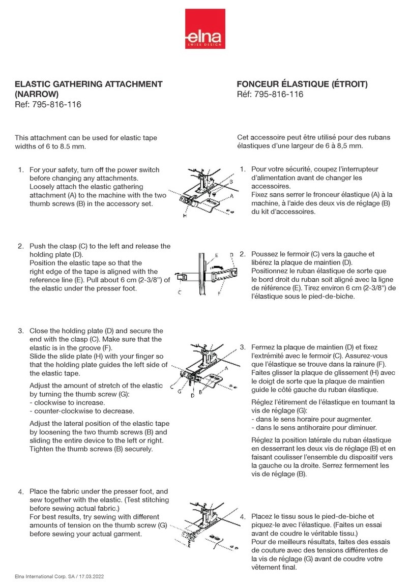
5.1 Installing the I/O Expansion Unit
(1) Turn off the power.
(2) Remove the circuit board cover as shown in Figure 1. (This cover is not used after the I/O
Expansion Unit attached.)
(3) Disconnect the extension cable for the power supply and signals of the circuit board.
(4) Disconnect the connector mounting plate. (This mounting plate is not used after the I/O Expansion
Unit attached.)
(5) Remove the connector "SEN 1" , "CON L" and "CON M" from the connector mounting plate as
shown in Figure 1.
(6) Remove the two hexagon socket head cap screws shown in Figure 2.
(7) Attach the Fig.No.110 bracket using the screw holes of the previous section by screws "M4"
provided.
(8)Attach the connector "CON L" and "CON M" to the Fig.No.102 connector mounting plate.
(9) Attach the connector "CON N" on the I/O Expansion Unit shown in Figure 2 to the Fig.No.102
connector mounting plate.
(10) Attach the Fig.No.102 connector mounting plate to the sewing machine by the screws "M4"
provided.
(11) Connect the connector "SEN 2" of the I/O Expansion Unit and the connector "SEN 1".
(12) Connect the connector "CON 2" of the circuit board and the signal line of the I/O Expansion Unit.
(13) Attach the extension board assembly consisting of Fig.No.106 to the Fig.No.102 connector
mounting plate by the screws "M4" provided.
(14) Connect the extension cable for the power supply to the connector "CON N". Connect the
extension cable for the signals to the circuit board.
(15) Attach the Fig.No.101 cover to the sewing machine by the screw "M4" provided.
★When installing removal of parts, please go to turn off the power before. In addition,
qualified personnel of electrical work, please be performed by wiring work.
