JUKI MP-G10-TH User manual

INDUSTRIAL SEWING MACHINE
MODEL
MP-G10-TH
TECHNICAL MANUAL
Upper Thread-Holding Device
A181E018P01
Attachment


FOR SAFE USE
Before the installation, operation, and inspection for this product, read the “FOR SAFE USE” and the technical
manuals carefully. Also read the other technical manuals, “Sewing Machine Head”, “Control Unit” and
“Operation Panel” describing some instructions, which are not in this manual, and use the sewing machine
properly.
SAFETY INDICATIONS
CAUTION
Indicates that incorrect handling may cause hazardous conditions, resulting in
medium or slight personal injury or physical damage. Note that CAUTION level
may lead to a serious consequence according to the circumstances. Always
follow the instructions of both levels because they are important to personal
safety.
CAUTION INDICATIONS
No.
Caution indication
Description
1
Precaution for sewing machine operation:
Indicates that removing the safety and operating the sewing machine
for some other purposes with power-on are prohibited.
⚫Please do not operate the sewing machine without protective
equipment such as a needle guard, an eye guard, a belt cover
or the others.
⚫Please turn off the power switch when threading, changing a
needle and a bobbin, cleaning, and lubricating.
2
Caution for fingers injury:
Indicates a possibility of fingers (hands) injury in a certain condition.
3
Caution for squeezing fingers:
Indicates a possibility of squeezing fingers in a certain condition.

- 1 -
1. Features
Upper Thread-Holding Device will improve the
quality of the sewing start point. By gripping the
upper thread after thread trimming sewing end,
to prevent the thread fall out at the sewing start
point.
2. Applicable models
PLK-G1010
3. Specifications
Upper thread holding stroke
:23mm
Control power supply
:DC24V
Drive source air pressure
Primary side
:0.5 MPa(5 kgf /cm2)or more
Secondary side
:0.4 MPa(4 kgf /cm2)
Fig.1
Mounting example of
the upper thread holding mechanism
Trouble such as operation errors could occur if the secondary pressure is set too high.
Use within the range of 0.4 MPa (4 kgf /cm2).
CAUTION

- 2 -
4. Configuration
The Fig. numbers in the drawing correspond to the part numbers given in the following explanations. When
ordering service parts, please specify in the Parts No. (M********).
4.1 Upper thread holding mechanism
4.1 Upper thread holding mechanism (Parts list)
Fig
部品コード
品名
Description
数量
No.
Parts No.
Amt. Req.
101
MB10H0429
ササエイタ
Support plate
1
102
MB10H0751
トリツケブロック
Installation block
1
103
M90859004
SW-PW プラマイナベネジ M3X6
Screw M3X6
3
104
MB10H0700
ホジバネ
Holding spring
1
105
MB10H0477
ストッパ
Stopper
1
106
ML30A0181
イトサバキ
Thread distributor
1
107
MA20A9571
ワンタッチツギテ
One-touch coupling
2
108
ME25H0434
エアシリンダ
Air cylinder
1
4.2 Pneumatic pressure control unit
107A
An example of a
mounting bracket
(Not included)
103
Fig.2
Upper thread holding mechanism
108
107B
101
105
102
103
106
104

- 3 -
4.2 Pneumatic pressure control unit (Parts list)
Fig
部品コード
品名
Description
数量
No.
Parts No.
Amt. Req.
201
MH25A1601
デンジベントリツケイタ
Valve mounting plate
1
202
M91066004
SW-PW プラマイナベネジ M4X25
Screw M4X25
4
203
ME10X0599
デンジベンクミタテ
Solenoid valve assy
1
204
M90511050
ザガネ 5
Washer 5
2
205
M95003017
セフティソケット M5X8
Safety socket bolt M5X8
2
206
MH10A8508
セツゾクデンセンクミタテ
Cable assy
1
207
MB10K4567
エアチューブクミタテ(A)
Air tube assy (A)
1
208
MB10K5567
エアチューブクミタテ(B)
Air tube assy (B)
1
209
M91035089
サイレンサ
Muffler
2
210
MB20P1567
エアチューブ
Air tube
1
211
ME40A0963
フィルタレギュレータ
Filter regulator
1
212
MA20A8571
Lガタワンタッチツギテ
L-type quick joint
3
213
MA30A0964
レジューサ
Reducer
2
4.3 Accessories
4.3 Accessories (Parts list)
Fig
部品コード
品名
Description
数量
No.
Parts No.
Amt. Req.
301
MF06A1620
ケッソクバンド
Cable tie
4
302
M91010089
ロッカクソケット
Socket
1
303
MA30A0571
ワンタッチツギテ
Quick joint
1
304
MS06A0567
エアチューブ
Air tube
1
305
M90409041
マルモクネジ 4.5X20
Screw 4.5X20
2
301
305
302
303
304

- 4 -
5. Assembly procedures
5.1 Installing the upper thread holding mechanism
(1) Make a bracket for mounting the upper thread holding mechanism.
(Shows an example in Figure 2.)
★Please consult sewing machine shop for the fabrication of bracket.
The mounting of the upper thread holding mechanism, you can use the mounting holes of the wiper
mechanism, to or attached to the face cover. Attach a position that does not interfere with the holding jig
to position the sewing material, consider including the sewing pattern and workability.
(2) Remove the wiper mechanism from the machine arm. Is not only part of the wiper drive, please remove
the connection wires from the sewing machine.
★Can not be shared with the wiper mechanism and Upper Thread-Holding Device.
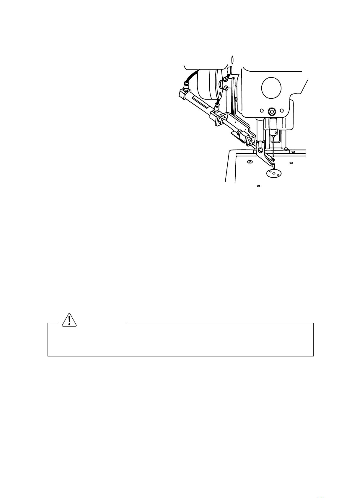
(3) Attach the upper thread holding mechanism to the machine arm. Please adjust the position of the upper
thread holding mechanism so that the thread distributor Fig.No.106 scoop a thread between the presser
foot and the needle, as shown in Figure 1.
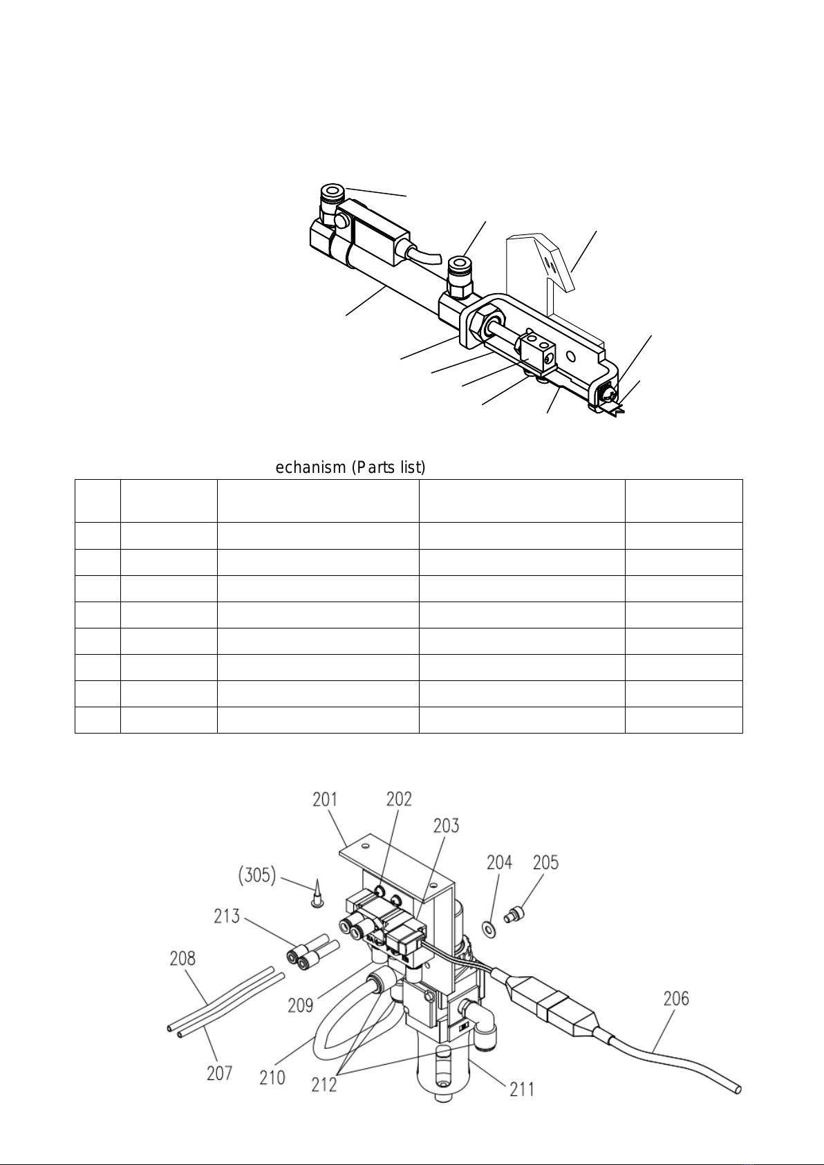
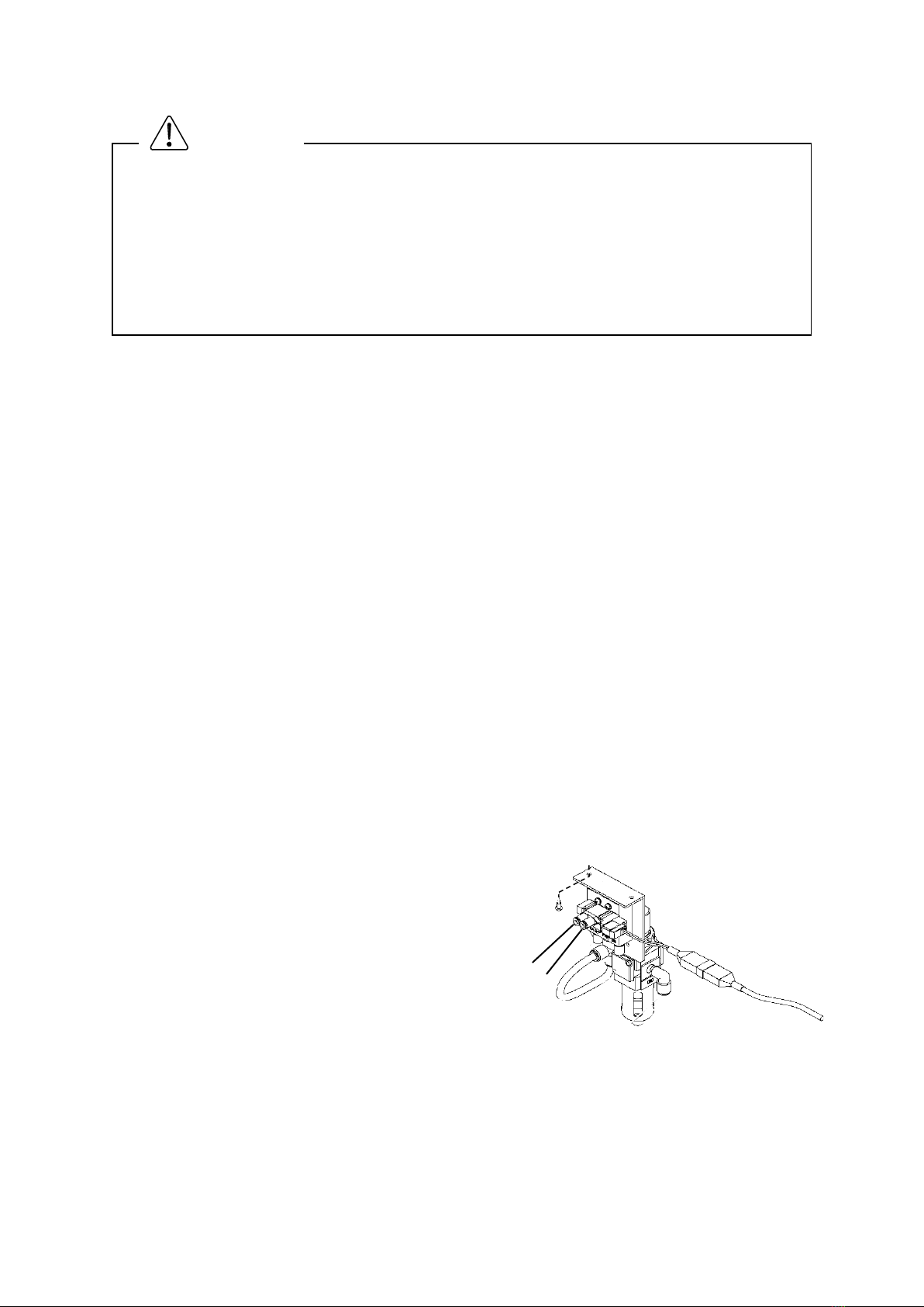
5.2 Installing the pneumatic pressure control related parts and piping
Please connect the pipes so that the state of the air cylinder rod is returned when the power is turned off. If
the rod is advanced, please replace the pipe to the joint A and B of the solenoid valve after the removal of
the air pressure to stop the air.
(1) Please fix with two wood screws provided
the pneumatic pressure control unit of sewing
machine table underside as shown in Figure
3.
(2) Insert to match the symbols A and B of the
air tubes "Fig.No.207 and 208" into the ports
"Fig.No.107A and 107B" of the upper thread
holding mechanism.
(3) Pass the air tubes through the notched
section on the side of the sewing machine
unit's motor cover, and lead the tubes to the
bottom of the table from the square hole on
the table.
(4) Insert to match the symbols A and B of the
air tubes into the ports "A and B" of the
solenoid valve.
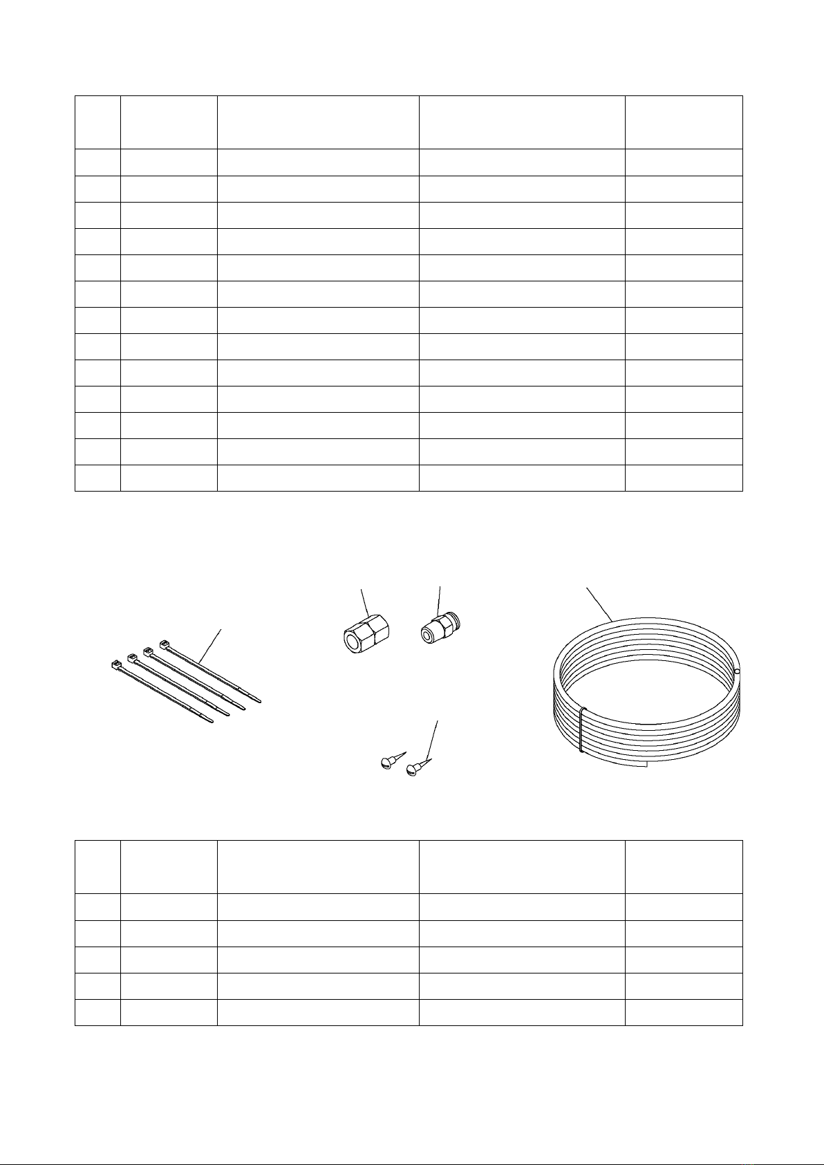
(5) Bind the air tubes appropriately with the
enclosed Fig.No.301 Cable ties.
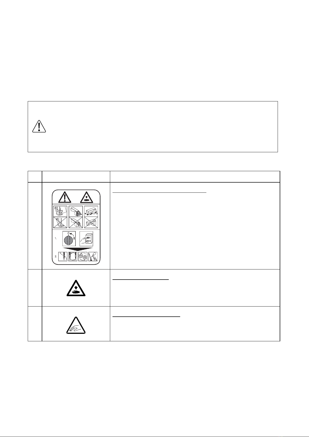
★To work in the presence of residual pressure in the pneumatic circuit It is dangerous. Please
work after you remove the residual pressure always. The method of removing the residual
pressure, and pull up the handle of the pressure regulating filter regulator, can be done by turning
counter-clockwise until the pressure gauge shows 0.
★When installing removal of parts, please go to turn off the power before. In addition, qualified
personnel of electrical work, please be performed by wiring work.
CAUTION
Fig.3
B
A

- 5 -
5.3 How to setup and cable connection
(1) Remove the circuit board cover on the back of the sewing machine.
(2) Disconnect the cable connector of the wiper connected to CON11 on the circuit board.
(3) Connect the connector of Fig.No.203 cable assy to CON11 on the circuit board.
(4) Connect the connector of sensor of the air cylinder to CON9 on the circuit board.
(5) Install the circuit board cover removed.
Output (CON 11)
Printed character
Signal
Pin No.
W
O2
Upper thread holding
1
-
-
2
+24V
DC24V
3
Input (CON 9)
Printed character
Signal
Pin No.
FSW
+12V
DC12V
1
I7
S6
(Thread trimming protection signal)
2
GND
Ground
3
5.4 How to setup and cable connection
(1) Press the on the standard screen to open the MENU mode.
(2) Press the in the menu icon. The Input/Output setting mode screen is displayed.
(3) Press the on the Input/Output setting mode, and enter a password.
Input Customize Setting screen, press the button on the lower side of the physical input RAM "I7".( Input
signal is displayed on the button, the default is "NO".) The Function Section screen will open.
(4) Select input signal "S6" by pressing the button .
(5) Press the and display the screen of the Detailed Setting.
(6) Change the "reversed" from the "normal" a logical setting by pressing the button ,
press the button .
(7) Press the .
(8) Press the and return to standard screen.
The settings will be changed to the table shown next by the above operation.
For details, refer to the clause [14] Input/output setting mode of the technical manual “Operation Panel”.
Please ask the dealer about a password.
DETAILED
SETTING
USUAL

Default value
After changing the setting
Input signal
NO
S6
Signal name
--
Thread trimming protection signal
Logical setting
normal
reversed
6. Operation
(1) Pull up on the handle of the filter regulator, adjust to 0.4MPa(4kgf/cm2) air pressure by turning in a
clockwise direction.
(2) Upper Thread-Holding Device will work in the program of the wiper.
For the timing adjustment of the operation, refer to the clause of the technical manual “Control Unit”.
7. Upper thread holding mechanism outline drawing
Assembly of this device is completed, please check your work once again.
Because there is a case to unexpected behavior, please away from the sewing machine when the
power is turned on and the air pressure.
CAUTION
2-M4 Internal thread
23str

MEMO


Printed in Japan
Table of contents
Other JUKI Sewing Machine Accessories manuals

JUKI
JUKI DDL-7000A-7 Series User manual

JUKI
JUKI MP-G20R-TH User manual

JUKI
JUKI JaNets JT Simple User manual

JUKI
JUKI MP-G50-TE User manual

JUKI
JUKI AK-121 User manual

JUKI
JUKI IP-200 User guide

JUKI
JUKI IP-420 User manual

JUKI
JUKI DLU-5494N-7/IP-110C User manual

JUKI
JUKI AE-9 User manual

JUKI
JUKI IP-410 User manual
Popular Sewing Machine Accessories manuals by other brands

Quilt EZ
Quilt EZ BUTLER Assembly instructions

Bernette
Bernette Snap Hoop Monster manual

Baby Lock
Baby Lock BLRG20ST Instruction and reference guide

DURKOPP ADLER
DURKOPP ADLER 550-867 Additional instructions

Newlong
Newlong DS-9 Instruction manual & parts list

Baby Lock
Baby Lock GALLANT BLGT15-RH installation instructions