JUKI PS800-8045 User manual

CAUTION :
This Instruction Manual provides instructions for the active tension. When you want to use
your sewing machine with this product attached, refer to the “Safety precautions” in the In-
struction Manual for your sewing machine carefully until you fully understand the included
precautions in prior.
PS-800-8045
Active tension
INSTRUCTION MANUAL

i
CONTENTS
1. List of parts ............................................................................................................................1
2. Assembling the parts ............................................................................................................ 3
3. Wiring (miscellaneous cover components of the sewing machine) ................................. 5
4. Wiring (inside the electrical equipment rack) ..................................................................... 6
5. Method for adjusting the AT ................................................................................................. 8
5-1. Setting of the parameters ............................................................................................................8
5-2. Adjusting the projection amount of the plunger........................................................................9
6. Method for using the AT...................................................................................................... 10
6-1. Method for setting the AT thread tension.................................................................................10
6-2. Method for changing the thread tension during sewing.........................................................12
6-3. Method for deleting the changes in thread tension setting during sewing ..........................13

– 1 –
1. List of parts
Active tension (asm.)
No. Part number Part name Qty
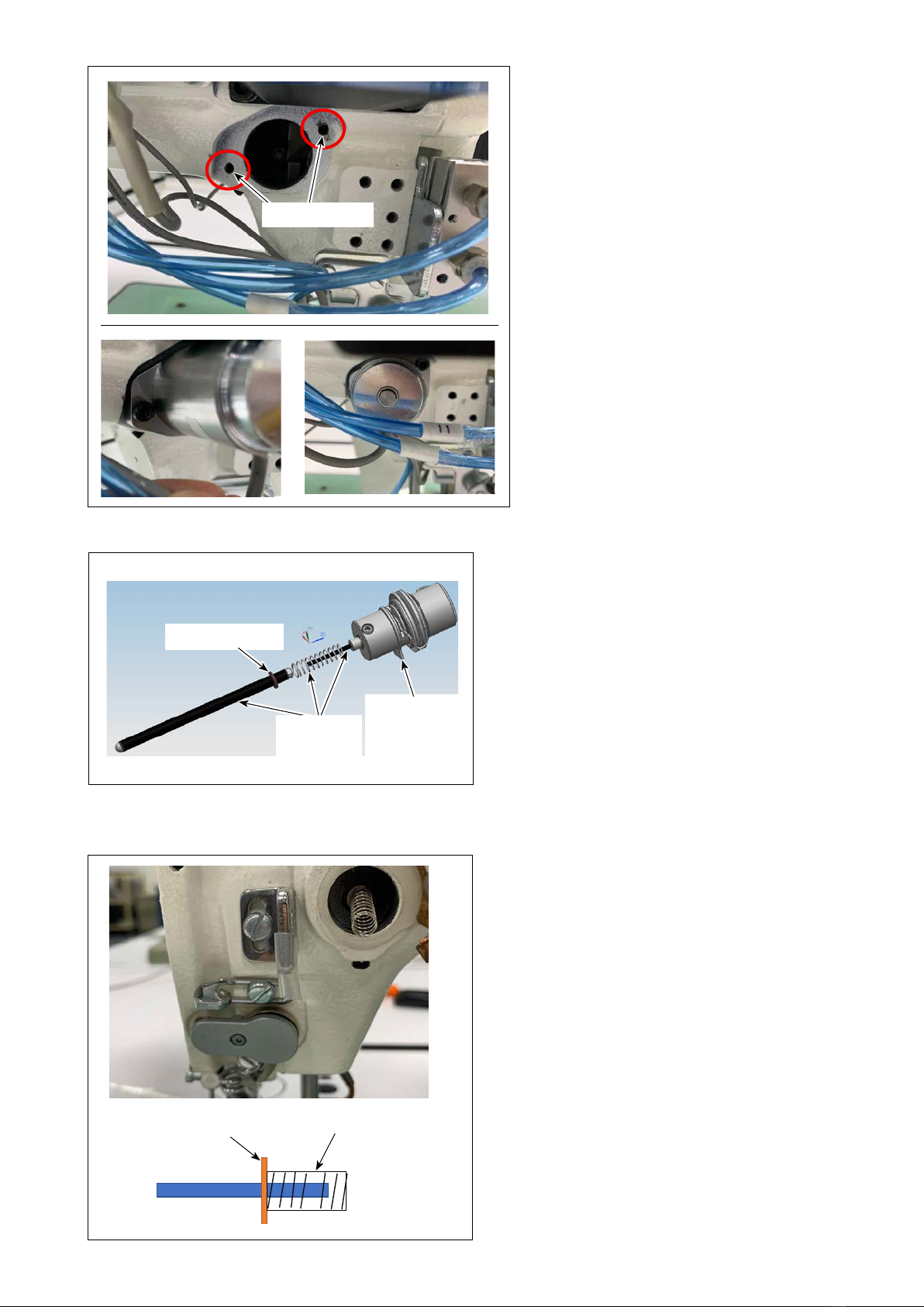
①40244934 Tension release auxiliary shaft (asm.) 1
①-1 40236683 Tension release auxiliary shaft (1)
①-2 40236685 Tension release auxiliary pin (1)
①-3 26201004 Guide pin (1)
①-4 RE0320000K0 E retaining ring (1)
②40244974 AT solenoid asm. 1
②-1 40236465 Solenoid (1)
②-2 RE0500000K0 E retaining ring (1)
②-3 NM6040000SN Hexagonal nut M4 1 type (1)
②-4 40236686 Solenoid screw (1)
②-5 40236680 Solenoid mounting plate (1)
②-6 40236681 Left AT shaft bushing (1)
②-7 SM1850600SP Countersunk head screw (2)
②-8 SM6040802TP Bolt screw (2)
①40244934 Tension release auxiliary shaft
①-2
①-1
①-4 ①-3
②40244974 AT solenoid
②-4
②-3
②-2
②-1 ②-5
②-6
②-7
②-8
WARNING :
In order to prevent accidents caused by a sudden start of the sewing machine, the following proce-
dure has to be carried out after turning OFF the power supply and air supply to the sewing machine.

– 2 –
③④⑤
No. Part number Part name Qty
③40172470 Thread tension controller (asm.) 1
④40243919 AT spring 1
⑤SM6041402TP Bolt M4 L=14 2
⑥40243045 AT SOL PCB asm. 1
⑦40243046 AT SOL cable asm. A 1
⑧40243047 AT SOL cable asm. B 1
⑨KX000000210 Cable tie mount 2
⑩SM4051601SC Countersunk head screw M5 x 0.8 L=10 2
⑪HX002940000 Fixation base 1
⑫SM6041002TN Bolt M4, L=10 1
⑬EA9500B0200 Cable clip band 6
⑥
⑦
⑧
⑨ ⑪

– 3 –
1) Loosen screw ❶. Detach tension release
solenoid ❷.
2. Assembling the parts
❷❷
3) Detach the face plate. Take out tension disc
releasing solenoid tension release auxiliary
shaft asm. ❺from the solenoid mounting hole.
❹❹
❺❺
❶❶
❸❸
2) Loosen screw ❸. Detach thread tension con-
troller ❹.
Tension disc releasing solenoid
tension release auxiliary shaft asm.
Pull the auxiliary shaft in the direction
of the arrow until it comes off.
WARNING :
In order to prevent accidents caused by a sudden start of the sewing machine, the following proce-
dure has to be carried out after turning OFF the power supply and air supply to the sewing machine.

– 4 –
4) Secure AT solenoid asm ②in the
mounting hole with screws ⑤ (two
pieces).
6) Put the end Aof tension release auxiliary
shaft asm. ①into the thread tension con-
troller mounting hole.
Put spring ④on the end Bof the tension
release auxiliary shaft asm.
Mounting hole
End A End B
E retaining ring Spring
E retaining ring
Retaining ring
of the thread
tension con-
troller asm.
Grease
application
points
5) Put a little amount of grease (white) sup-
plied in the accessory bag on a piece of
cloth. Then, apply a thin coat of the grease
to the AT shaft, reseat spring and tension
release pin with that cloth.

– 5 –
3. Wiring (miscellaneous cover components of the sewing machine)
1) Wire AT solenoid ca-
ble ②along the route
indicated with the red
dotted line as shown
in the figure on the
left.
During this proce-
dure, change the
existing screw with
screw ⑫. Then,
secure fixing base ⑪
with it. Then, secure
the cable with cable
clip band ⑬.
2) Wire AT solenoid ca-
ble ②along the route
indicated with the red
dotted line as shown
in the figure on the
left.
During this proce-
dure, loosen the
screw and tighten
fixing base ⑨. Then,
secure the cable with
cable clip band ⑬.
7) Pressing the retaining spring of the AT
thread tension controller asm. against
the end surface of the tension controller
mounting hole, secure it with screw ❸at
a position where the stroke of the thread
take-up spring becomes 4 to 5 mm.
If you cannot press the retaining
spring of the thread tension con-
troller asm. against the end sur-
face of the mounting hole, loosen
bracket screw ❻of the AT thread
tension controller.
After pressing the retaining spring
against the end surface of the
mounting hole, temporarily tighten
bracket screw ❻.
⑪⑫⑬⑪⑫⑬
②②
⑨⑬
❸❸
4~5mm
❻❻

– 6 –
4. Wiring (inside the electrical equipment rack)
3) Pull AT solenoid cable ②into the electrical
equipment rack through cable entrance of the
rack.
Cable entrance
1) Connect AT solenoid cable ②and AT SOL cable asm. A ⑦to the AT SOL PCB asm. ⑥in the elec-
trical equipment rack.
[Standard type and the laser type]
⑥⑥
②②⑥⑥⑦⑦
GND
LOOSE
24V
2) Insert the pin contact of the black wire (GND) of AT SOL cable asm. A ⑦into IN6/IN7 connector pin
No. 4.
3) Connect AT SOL cable asm. A connector ⑦to the loose line / LOOSE connector of the electrical
control box.
Pin No. 4
Loose thread
IN6/IN7

– 7 –
⑬⑬
[ Rotary knife type ]
⑥⑥
②②⑥⑥⑧⑧
GND
LOOSE
24V
5) Connect AT solenoid ②cable and AT SOL cable asm. B ⑧to AT SOL PCB asm. ⑥in the electrical
equipment rack.
6) Connect terminals of AT SOL cable asm. B ⑧
to the IO PCB.
Refer to the table shown below for the connec-
tion destinations of the respective terminals.
Color of line Cable Connection desti-
nation
Brown -24V +24V
Gray LOOSE Loose thread -
Black GND GND
7) Put the cables together in the duct.
Loose thread -
+24V
GND
4) Put the cables together in the duct. Secure the
PCB with cable clip band ⑬.
PCB

– 8 –
5. Method for adjusting the AT
1) Press button A.
5-1. Setting of the parameters
2) Press button B.
In the default state, the password that has
been factory-prepared at the time of delivery is
provided.
The factory-provided password is "11111111".
3) Press button C.
A
B
C
E
D F
4) When you want to enable the AT function,
change the setting of Dfrom "Tension disk
release" to "Thread clamp".
In the case of the sewing machine for light-
weight materials, set correction value Fto
"-10". After you have set the correction value,
press button E.

– 9 –
5-2. Adjusting the projection amount of the plunger
1) Press plunger ❶of the solenoid into the so-
lenoid. Measure projection amount ❷of the
plunger.
2) Loosen screw ❸of the thread tension control-
ler bracket. Adjust the longitudinal position of
the bracket so that projection amount ❷of the
plunger becomes 1.5 ± 0.1 mm. Then, tighten
screw ❸.
❸❸
❶❶
❷❷

– 10 –
6. Method for using the AT
1) Select the sewing pattern thread tension for
which you want to set.
2) Press presser foot/thread tension setting but-
ton A.
6-1. Method for setting the AT thread tension
3) The tension can be set by pressing default
tension B. Input any set value you desire and
carry out trial stitching.
Observing the stitches produced by trial stitch-
ing, confirm the appropriate tension set value.
4) Press return button Cto return to the main
screen.
A
C B

– 11 –
5) Press the reset button Don the main screen
to return to the origin.
6) Press in the same way as in step 2) to en-
ter the tension setting screen, and enter the
tension setting value confirmed in step 3) into
tension 1E.
Set the default tension Bto "1".
30
Thread tension 1 at the start of sewing : 30
1. The default tension and tension
1 settings are valid from 1 to
100 (integers only).
2. To set the default tension, just
check the appropriate tension
by trial sewing, and set tension
1 during production.
D
B
E

– 12 –
6-2. Method for changing the thread tension during sewing
1) Set the thread tension in the entry field of
"Thread tension 1" at a midpoint of the stitch-
ing line at which you want to change the
thread tension.
2) If you want to change the thread tension again
during sewing, set the thread tension in the
entry field of "Thread tension 1" at a desired
midpoint of the stitching line.
The thread tension set in the entry
field of "Thread tension 1" remains
the same until the sewing is com-
pleted.
Thread tension setting method in the case of the
picture shown on the left
30 60
Thread tension 1 at the start of sewing : 30
Thread tension from the changing point -
(To the end of sewing) : 60
Thread tension setting method in the case of the
picture shown on the left
30 30
Thread tension 1 at the start of sewing : 30
Thread tension from the rst changing point - : 60
Thread tension from the second changing point -
(To the end of sewing) : 30
60
Change the
thread tension
Be sure to set the thread tension in this
entry eld when you want to change the
thread tension during sewing.

– 13 –
6-3. Method for deleting the changes in thread tension setting during sewing
1) If you press "Tension 1 button" Aand "delete
button" B, individual thread tension settings
you have set in a sewing pattern will be totally
deleted.
2) If you wan to delete the individual thread
tension settings separately, move cross mark
cursor ( ) to the target thread tension setting
position and press delete button B.
B
A
Other manuals for PS800-8045
2
Table of contents
Other JUKI Sewing Machine Accessories manuals

JUKI
JUKI AK-121 User manual

JUKI
JUKI IP-200 User guide

JUKI
JUKI DDL-7000A-7 Series User manual

JUKI
JUKI DLU-5494N-7/IP-110C User manual

JUKI
JUKI JaNets JT Simple User manual

JUKI
JUKI MP-G20R-TH User manual

JUKI
JUKI AE-9 User manual

JUKI
JUKI MP-G10-TH User manual

JUKI
JUKI PS-800SB-2850 Series User manual

JUKI
JUKI IP-410 User manual