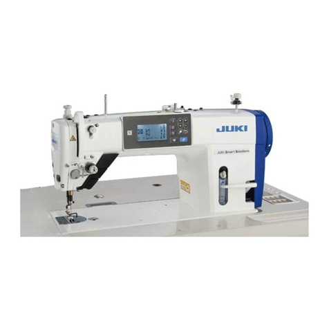
JUKI DDL-9000B User manual

No.01
40089324
DDL-9000B
取扱説明書
INSTRUCTION MANUAL
BETRIEBSANLEITUNG MANUEL D’UTILISATION
MANUAL DE INSTRUCCIONES
MANUALE D’ISTRUZIONI
使用说明书
KULLANMA KILAVUZU
ИНСТРУКЦИЯ ПО ЭКСПЛУАТАЦИИ
注意: このたびは、当社の製品を、お買い上げいただきまして、有難うございました。
安全に使用していただくために、使用前に必ずこの取扱説明書をお読みください。
また、いつでもすぐに読めるように、この取扱説明書を保管してください。
NOTE : Read safety instructions carefully and understand them before using.
Retain this Instruction Manual for future reference.
HINWEIS :
Lesen Sie die Sicherheitsanweisungen aufmerksam durch, um sich mit ihnen vertraut zu
machen, bevor Sie diese Maschine in Betrieb nehmen. Bewahren Sie diese Bedienungsanleitung
für spätere Bezugnahme auf.
NOTE : Avant d’utiliser la machine, lire attentivement toutes les consignes de sécurité.
Conserver ce manuel pour pouvior le consulter en cas de besoin.
NOTA : Antes de comenzar a usar esta máquina lea con detención hasta comprender todas las
instrucciones de sequridad. Conserve este Manual de instrucciones a mano para futuras
consultas.
NOTA : Leggere attentamente e compredere tutte le istruzioni per la sicurezza prima di inziare l’ uso
di questa macchina. Conservare questo Manuale d’Instruzioni per pronto riferimento.
注意 : 为了安全地使用,请您在使用之前一定阅读本使用说明书。
另外,请您注意保管本使用说明书,以便随时查阅。
NOT : Güvenlik talimatını dikkatle okuyun ve makineyi kullanmadan önce tümüyle öğrenin.
Gelecekte de yararlanmak için, bu kullanma kılavuzunu muhafaza edin.
ЗАМЕЧАНИЯ : Внимательно прочитайте и усвойте правила техники безопасности перед использованием
швейной машины. Сохраните эту инструкцию по эксплуатации для того, чтобы обращаться к
ней и в будущем.


ENGLISH
ENGLISH


i
ENGLISH
1• There is the possibility that slight to serious injury or death may be caused.
• There is the possibility that injury may be caused by touching moving part.
2• To perform sewing work with safety guard.
• To perform sewing work with safety cover.
• To perform sewing work with safety protection device.
3• Be sure to turn the power OFF before carrying out "machine-head threading," "needle changing," "bobbin
changing" or "oiling and cleaning."
For the sewing machine, automatic machine and ancillary devices (hereinafter collectively referred to as
"machine"), it is inevitable to conduct sewing work near moving parts of the machine. This means that there
is always a possibility of unintentionally coming in contact with the moving parts. Operators who actually
operate the machine and maintenance personnel who are involved in maintenance and repair of the
machine are strongly recommended to carefully read to fully understand the following Safety precautions
before using/maintaining the machine. The content of the Safety precautions includes items which are not
containedinthespecicationsofyourproduct.
Theriskindicationsareclassiedintothefollowingthreedifferentcategoriestohelpunderstandthemeaning
of the labels. Be sure to fully understand the following description and strictly observe the instructions.
TO ENSURE SAFE USE OF YOUR SEWING MACHINE
(
!
) Explanation of risk levels
This indication is given where there is a potentiality for death or serious injury if the person in charge or any third
party mishandles the machine or does not avoid the dangerous situation when operating or maintaining the machine.
This indication is given where there is an immediate danger of death or serous injury if the person in charge or any third
party mishandles the machine or does not avoid the dangerous situation when operating or maintaining the machine.
This indication is given where there is a danger of medium to minor injury if the person in charge or any third party
mishandles the machine or does not avoid the dangerous situation when operating or maintaining the machine.
DANGER :
WARNING :
CAUTION :
(
@
)
Explanation of pictorial warning indications and warning labels
Pictorial
warning
indication
There is a risk of injury
if contacting a moving
section.
There is a risk of
entanglement in the belt
resulting in injury.
There is a risk of
electrical shock if
contacting a high-voltage
section. Indication
label
The correct direction is
indicated.
There is a risk of a burn
if contacting a high-
temperature section.
Connection of a earth
cable is indicated.
3
2
1
1
23
Items requiring special attention

ii
Turning the power off: Turning the power switch off, then removing the power plug from the outlet. This
applies to the following.
SAFETY PRECAUTIONS
1.
When it is necessary to open the control box containing electrical parts, be sure to turn the power off and
wait for ve minutes or more before opening the cover in order to prevent accident leading to electrical
shock.
CAUTION
Basic precaution
1. Be sure to read the instruction manual and other explanatory documents supplied with accessories
of the machine before using the machine. Carefully keep the instruction manual and the explanatory
documents at hand for quick reference.
2. The content of this section includes items which are not contained in the specications of your product.
3. Be sure to wear safety goggles to protect against accident caused by needle breakage.
4. Those who use a heart pacer have to use the machine after consultation with a medical specialist.
Safety devices and warning labels
1. Be sure to operate the machine after verifying that safety device(s) is correctly installed in place and
works normally in order to prevent accident caused by lack of the device(s).
2. If any of the safety devices is removed, be sure to replace it and verify that it works normally in order to
prevent accident that can result in personal injury or death.
3. Be sure to keep the warning labels adhered on the machine clearly visible in order to prevent accident
that can result in personal injury or death. If any of the labels has stained or come unstuck, be sure to
change it with a new one.
Application and modication
1.
Never use the machine for any application other than its intended one and in any manner other than that
prescribed in the instruction manual in order to prevent accident that can result in personal injury or death.
JUKI assumes no responsibility for damages or personal injury or death resulting from the use of the
machine for any application other than the intended one.
2.
Never modify and alter the machine in order to prevent accident that can result in personal injury or death.
JUKI assumes no responsibility for damages or personal injury or death resulting from the machine
which has been modied or altered.
Education and training
1. In order to prevent accident resulting from unfamiliarity with the machine, the machine has to be used
only by the operator who has been trained/educated by the employer with respect to the machine
operation and how to operate the machine with safety to acquire adequate knowledge and operation
skill. To ensure the above, the employer has to establish an education/training plan for the operators and
educate/train them beforehand.
Items for which the power to the machine has to be turned off
Accident means "to cause
personal injury or death or
damage to property."
1. Be sure to immediately turn the power off if any abnormality or failure is found or in the case of power
failure in order to protect against accident that can result in personal injury or death.
2. To protect against accident resulting from abrupt start of the machine, be sure to carry out the following
operations after turning the power off. For the machine incorporating a clutch motor, in particular, be
sure to carry out the following operations after turning the power off and verifying that the machine
stops completely.
2-1. For example, threading the parts such as the needle, looper, spreader etc. which have to be
threaded, or changing the bobbin
2-2. For example, changing or adjusting all component parts of the machine.
2-3. For example, when inspecting, repairing or cleaning the machine or leaving the machine
3. Be sure to remove the power plug by holding the plug section instead of the cord section in order to
prevent electrical-shock, earth-leakage or re accident.
4. Be sure to turn the power off whenever the machine is left unattended between works.
5. Be sure to turn the power off in the case of power failure in order to prevent accident resulting of
breakage of electrical components.
DANGER
PRECAUTIONS TO BE TAKEN IN VARIOUS OPERATION STAGES
Transportation
1. Be sure to lift and move the machine in a safe manner taking the machine weight in consideration. Refer
to the text of the instruction manual for the mass of the machine.

iii
ENGLISH
2. Be sure to take sufcient safety measures to prevent falling or dropping before lifting or moving the
machine in order to protect against accident that can result in personal injury or death.
3. Once the machine has been unpacked, never re-pack it for transportation to protect the machine against
breakage resulting from unexpected accident or dropping.
Unpacking
1. Be sure to unpack the machine in the prescribed order in order to prevent accident that can result in
personal injury or death. In the case the machine is crated, in particular, be sure to carefully check nails.
The nails have to be removed.
2. Be sure to check the machine for the position of its center of gravity and take it out from the package
carefully in order to prevent accident that can result in personal injury or death.
Installation
(!)Table and table stand
1. Be sure to use JUKI genuine table and table stand in order to prevent accident that can result in
personal injury or death. If it is inevitable to use a table and table stand which are not JUKI genuine
ones, select the table and table stand which are able to support the machine weight and reaction force
during operation.
2. If casters are tted to the table stand, be sure to use the casters with a locking mechanism and lock
them to secure the machine during the operation, maintenance, inspection and repair in order to prevent
accident that can result in personal injury or death.
(@)Cable and wiring
1. Be sure to prevent an extra force from being applied to the cable during the use in order to prevent
electrical-shock, earth-leakage or re accident. In addition, if it is necessary to cable near the operating
section such as the V-belt, be sure to provide a space of 30 mm or more between the operating section
and the cable.
2. Be sure to avoid starburst connection in order to prevent electrical-shock, earth-leakage or re accident.
3. Be sure to securely connect the connectors in order to prevent electrical-shock, earth-leakage or re
accident. In addition, be sure to remove the connector while holding its connector section.
(#)Grounding
1. Be sure to have an electrical expert install an appropriate power plug in order to prevent accident
caused by earth-leakage or dielectric strength voltage fault. In addition, be sure to connect the power
plug to the grounded outlet without exceptions.
2. Be sure to ground the earth cable in order to prevent accident caused by earth leakage.
($)Motor
1. Be sure to use the specied rated motor (JUKI genuine product) in order to prevent accident caused by
burnout.
2. If a commercially available clutch motor is used with the machine, be sure to select one with an
entanglement preventive pulley cover in order to protect against being entangled by the V-belt.
Before operation
1. Be sure to make sure that the connectors and cables are free from damage, dropout and looseness
before turning the power on in order to prevent accident resulting in personal injury or death.
2. Never put your hand into the moving sections of the machine in order to prevent accident that can result
in personal injury or death.
In addition, check to be sure that the direction of rotation of the pulley agrees with the arrow shown on pulley.
3. If the table stand with casters is used, be sure to secure the table stand by locking the casters or with
adjusters, if provided, in order to protect against accident caused by abrupt start of the machine.
During operation
1. Be sure not to put your ngers, hair or clothing close to the moving sections such as the handwheel,
hand pulley and motor or place something near those sections while the machine is in operation in order
to prevent accident caused by entanglement that can result in personal injury or death.
2. Be sure not to place your ngers near the surround area of the needle or inside the thread take-up lever
cover when turning the power on or while the machine is in operation in order to prevent accident that
can result in personal injury or death.
3. The machine runs at a high speed. Never bring your hands near the moving sections such as looper,
spreader, needle bar, hook and cloth trimming knife during operation in order to protect your hands
against injury. In addition, be sure to turn the power off and check to be sure that the machine
completely stops before changing the thread.
4. Be careful not to allow your ngers or any other parts of your body to be caught between the machine
and table when removing the machine from or replacing it on the table in order to prevent accident that
can result in personal injury or death.
5.
Be sure to turn the power off and check to be sure that the machine and motor completely stop before
removing the belt cover and V-belt in order to prevent accident caused by abrupt start of the machine or motor.
6.
If a servomotor is used with the machine, the motor does not produce noise while the machine is at rest.
Be sure not to forget to turn the power off in order to prevent accident caused by abrupt start of the motor.
7. Never use the machine with the cooling opening of the motor power box shielded in order to prevent re
accident by overheat.
iv
Lubrication
1. Be sure to use JUKI genuine oil and JUKI genuine grease to the parts to be lubricated.
2.
If the oil adheres on your eye or body, be sure to immediately wash it off in order to prevent inammation or irritation.
3. If the oil is swallowed unintentionally, be sure to immediately consult a medical doctor in order to
prevent diarrhea or vomiting.
Maintenance
1. In prevention of accident caused by unfamiliarity with the machine, repair and adjustment has to be
carried out by a service technician who is thoroughly familiar with the machine within the scope dened
in the instruction manual. Be sure to use JUKI genuine parts when replacing any of the machine parts.
JUKI assumes no responsibility for any accident caused by improper repair or adjustment or the use of
any part other than JUKI genuine one.
2. In prevention of accident caused by unfamiliarity with the machine or electrical-shock accident, be
sure to ask an electrical technician of your company or JUKI or distributor in your area for repair and
maintenance (including wiring) of electrical components.
3. When carrying out repair or maintenance of the machine which uses air-driven parts such as an air
cylinder, be sure to remove the air supply pipe to expel air remaining in the machine beforehand, in
order to prevent accident caused by abrupt start of the air-driven parts.
4. Be sure to check that screws and nuts are free from looseness after completion of repair, adjustment
and part replacement.
5. Be sure to periodically clean up the machine during its duration of use. Be sure to turn the power off
and verify that the machine and motor stop completely before cleaning the machine in order to prevent
accident caused by abrupt start of the machine or motor.
6. Be sure to turn the power off and verify that the machine and motor stop completely before carrying out
maintenance, inspection or repair of the machine. (For the machine with a clutch motor, the motor will
keep running for a while by inertia even after turning the power off. So, be careful.)
7. If the machine cannot be normally operated after repair or adjustment, immediately stop operation and
contact JUKI or the distributor in your area for repair in order to prevent accident that can result in
personal injury or death.
8.
If the fuse has blown, be sure to turn the power off and eliminate the cause of blowing of the fuse and replace
the blown fuse with a new one in order to prevent accident that can result in personal injury or death.
9. Be sure to periodically clean up the air vent of the fan and inspect the area around the wiring in order to
prevent re accident of the motor.
Operating environment
1. Be sure to use the machine under the environment which is not affected by strong noise source
(electromagnetic waves) such as a high-frequency welder in order to prevent accident caused by
malfunction of the machine.
2. Never operate the machine in any place where the voltage uctuates by more than "rated voltage±10 %"
in order to prevent accident caused by malfunction of the machine.
3. Be sure to verify that the air-driven device such as an air cylinder operates at the specied air pressure
before using it in order to prevent accident caused by malfunction of the machine.
4.
To use the machine with safety, be sure to use it under the environment which satises the following conditions:
Ambient temperature during operation 5℃ to 35℃
Relative humidity during operation 35 % to 85 %
5.
Dew condensation can occur if bringing the machine suddenly from a cold environment to a warm one.
So, be sure to turn the power on after having waited for a sufcient period of time until there is no sign of
water droplet in order to prevent accident caused by breakage or malfunction of the electrical components.
6. Be sure to stop operation when lightning ashes for the sake of safety and remove the power plug in
order to prevent accident caused by breakage or malfunction of the electrical components.
7. Depending on the radio wave signal condition, the machine may generate noise in the TV or radio. If this
occurs, use the TV or radio with kept well away from the machine.
8. For the worker who is involved in the work to be done in the environment relevant to "noise value in the
working environment is 85 dB or more and less than 90 dB", be sure to take appropriate measures, as
required, such as the use of ear protection or the like to protect against health hazard. In addition, for the
worker who is involved in the work to be done in the environment relevant to "noise level in the working
environment is 90 dB or more," be sure to instruct him/her to wear ear protection without exceptions in
order to protect against health hazard, and display a sign explaining how to use the ear protection at an
easily viewable location for the worker.

v
ENGLISH
FOR SAFE OPERATION
1. For the safety, never operate the sewing machine with the ground wire for the power
supply removed.
2. Be sure to turn OFF the power switch in prior when connecting/disconnecting the power
plug.
3. When thunders occurs, stop the work for the safety and disconnect the power plug.
4. When the sewing machine is suddenly moved from a cold place to a warm place, there
is a case where dew condensation may occur. Turn ON the power after there is no worry
of the drop of water.
5. To prevent res, periodically draw out the power plug from the plug socket and clean
the root of the pins and the space between pins.
6. The hook rotates at a high speed while the machine is in operation.
To prevent possible injury to hands, be sure to keep your hands away from the vicinity
of the hook during operation. In addition, be sure to turn OFF the power to the machine
when replacing the bobbin.
7. The motor does not produce noise while the machine is at rest.
To avoid possible accidents due to abrupt start of the machine, be sure to turn OFF the
power to the machine.
8. Be careful of handling this product so as not to pour water or oil, shock by dropping, and
the like since this product is a precision instrument.
9. When tilting or returning the sewing machine to the home position, hold the upper side of
the machine head with both hands and perform the work quietly so that ngers or the like
are not caught in the machine.
10. Never lower the needle bar when the picker is brought close to the bobbin. The picker
may be damaged by the needle, causing a stitching failure.
11. When the sewing machine is used for the rst time after delivery or after an extended
time of disuse, remove rubber plug from the frame cover and apply a few drops of oil
to the needle bar. If the sewing machine is used with no oil added to the needle bar, the
needle bar may be seized due to abrasion of the needle bar or intrusion of dust.
1. To avoid personal injury, never put your ngers under the needle when you turn ON the
power switch or operate the sewing machine.
2. To avoid personal injury, never put your ngers into the thread take-up cover while the
sewing machine is in operation.
3.
To avoid personal injury, turn OFF the power switch when you tilt the machine head.
4. To prevent possible personal injury caused by being caught in the machine, keep your
ngers, head and clothes away from the handwheel and the thread take-up while the
sewing machine is in operation. In addition, place nothing around it.
5. To avoid personal injury, never operate the sewing machine with the nger guard
removed.
6. To avoid personal injury, be careful not to allow your ngers in the machine when tilting
the machine head.
7. Be sure to mount the machine head support bar on the machine table so that its height
from the table surface becomes 55 to 60 mm. For the sewing machine provided with
the AK device, be sure to mount the support bar on the table so that its height from the
table surface becomes 38 to 43 mm.

vi
CAUTION BEFORE OPERATION
• Remove the air-vent cap (red color) attached to the sewing machine bed.
• Clean the sewing machine thoroughly before using it for the rst time.
• Remove all dust collected on the sewing machine during the transportation.
• Conrm that the voltage and phase are correct.
• Conrm that the power plug is properly connected.
• Never use the sewing machine in the state where the voltage type is different from the
designated one.
• The direction of rotation of the sewing machine is counterclockwise as observed from the
handwheel side. Be careful not to rotate it in reverse direction.
• Do not tilt the machine head toward this side since oil leakage or parts breakage occurs.
• A safety switch is installed so that the sewing machine cannot be operated with the machine
head tilted.
• When operating the sewing machine, turn ON the power switch after properly setting the head
on the table.
• Before starting a test run, remove the bobbin case and the needle thread from the machine.
• Operate the handwheel after the sewing machine has totally stopped.
WARNING :
To avoid malfunction and damage of the machine, conrm the following.

vii
ENGLISH

viii
CONTENTS
SPECIFICATIONS.................................................................................................................................................................................................1
1. INSTALLATION..........................................................................................................................................................................................1
2. ADJUSTING THE HEIGHT OF THE KNEE LIFTER .................................................................................................................................2
3. INSTALLING THE THREAD STAND.........................................................................................................................................................2
4. LUBRICATION (DDL-9000B-S , -M ).....................................................................................................................................................2
5. ATTACHING THE NEEDLE .......................................................................................................................................................................3
6. SETTING THE BOBBIN INTO THE BOBBIN CASE.................................................................................................................................3
7. ADJUSTING THE AMOUNT OF OIL (OIL SPLASHES) IN THE HOOK (DDL-9000B-S , -M ) ............................................................3
8. ADJUSTING THE AMOUNT OF OIL IN THE HOOK (DDL-9000B-S , -M ) ..........................................................................................4
9. THREADING THE MACHINE HEAD .........................................................................................................................................................4
10. THREAD TENSION....................................................................................................................................................................................5
11. WINDING THE BOBBIN THREAD ............................................................................................................................................................5
12. PRESSER FOOT PRESSURE...................................................................................................................................................................5
13. ADJUSTING THE STITCH LENGTH ........................................................................................................................................................6
14. THREAD TAKE-UP SPRING AND ADJUSTING THE THREAD TAKE-UP STROKE..............................................................................6
15. ADJUSTING THE NEEDLE STOP POSITION ..........................................................................................................................................7
16. PEDAL PRESSURE AND PEDAL STROKE.............................................................................................................................................7
17. ADJUSTMENT OF THE PEDAL ...............................................................................................................................................................8
18. PEDAL OPERATION .................................................................................................................................................................................8
19. NEEDLE-TO-HOOK RELATIONSHIP........................................................................................................................................................9
20. ONE-TOUCH TYPE REVERSE FEED STITCHING CHANISM.................................................................................................................9
21. ADJUSTING THE POSITION OF THE WIPER (DDL-9000B- -WB, -0B)..........................................................................................10
22. COUNTER KNIFE .................................................................................................................................................................................... 11
23. HEIGHT AND TILT OF THE FEED DOG ................................................................................................................................................ 11
24. ADJUSTING THE FEED TIMING.............................................................................................................................................................12
25. THREAD TENSION RELEASE RELEASING MECHANISM...................................................................................................................12
26. MICRO-LIFTING MECHANISM OF THE PRESSER FOOT....................................................................................................................13
27. SEWING CONDENSED STITCHES ........................................................................................................................................................13
28. FEED CONVERSION SPRING MECHANISM (DDL-9000B-S , -M )...................................................................................................14
29. CARE........................................................................................................................................................................................................14

– 1 –
ENGLISH
SPECIFICATIONS
S : Micro-quantity lubrication
M :
Semi-dry
D :
Dry
S : Medium-weight materials
H :
Heavy-weight materials
A :
Light weight materials
• The sewing speed will vary depending on the sewing conditions. The sewing speed preset at the time of shipping is 4,000sti/min. The thread trimming
speed can be changed within the range of ( ). The thread trimming speed preset at the time of shipping is 500sti/min.
* 1 : When stitch length exceeds 4 mm or more, set the max. sewing speed to 4,000 sti/min or less for use.
* 2 : Needle used depends on the destination.
*3 : MA type is for light-weight materials. In the case the sewing machine is used with its speed of stitch set at 4,000 sti/min or higher, the presser
regulating spring and thread tension spring should be changed with S type ones.
DDL-9000B-
-SS
-MS
-DS -SH -MA
*3
Max. sewing speed
5,000 sti/min 4,000 sti/min 4,500 sti/min 5,000 sti/min
Thread trimming speed
500 sti/min (100 to 500sti/min)
Stitch length 5mm *1 4mm
Presser foot lift
(by knee lifter)
10 mm (standard) 15 mm (max.)
Needle*2 134 #65 to #110
DP×5 #65 to #110
134 #125 to #160
DP×5 #125 to #160
134 #60 to #75
DP×5 #60 to #75
DB×1 #9 to #18
DB×1 #9 to #18
DB×1 #20 to #23
DB×1 #20 to #23
DB×1 SAN10 #8 to #11
DB×1 SF #8 to #11
Lubricating oil
JUKI NEW DEFRIX OIL No. 1 or JUKI MACHINE OIL #7 - JUKI NEW DEFRIX OIL No. 1 or JUKI MACHINE OIL #7
Noise SS,MS,MA;
'- Equivalent continuous emission sound pressure level (LpA) at the workstation:
A-weightedvalueof77dBA;(IncludesKpA=2.5dBA);accordingtoISO10821-C.6.2-ISO11204GR2at4,000sti/min.
SH;
'- Equivalent continuous emission sound pressure level (LpA) at the workstation:
A-weightedvalueof77dBA;(IncludesKpA =2.5dBA);accordingtoISO10821-C.6.2-ISO11204GR2at4,000sti/min.
DS;
'- Equivalent continuous emission sound pressure level (LpA) at the workstation:
A-weighted value of 79 dBA;(IncludesKpA=2.5dBA);accordingtoISO10821-C.6.2-ISO11204GR2at4,000sti/min.
1. INSTALLATION 1) 2)
8)
23.5 mm 19.5 mm
1
2
4
3
A B
3)
4) 5)
1) Carrythesewingmachinewithtwopersonsasshowninthegureabove.
(Caution) Do not hold the handwheel.
2) Do not put protruding articles such as the screwdriver and the like at the location where the sewing machine is placed.
3) The under cover should rest on the four corners of the machine table groove. Mount rubber hinge seat 8onthetableandxitonthetablewithanail.
4) Fix two rubber seats 1on side A(operator’s side) using nails 2as illustrated above. Fix two cushion seats 3on side B(hinged side) using a rubber-based adhesive. Then place
under cover 4onthexedseats.
5) Remove air vent cap 5attached to the machine bed.
(Caution)
1. If the sewing machine is operated without removing air vent cap 5, oil leakage from gear box portion C may occur.
2. Be sure to attach cap 5when transporting the machine head in the state that the machine head is removed from the machine table.
6) Fit knee lifter pressing rod 6. Fit hinge 7intotheopeninginthemachinebed,andtthemachineheadtotablerubberhinge8before placing the machine head on cushions 9on
the four corners.
7) Securely attach head support rod !0 to the table until it goes no further. Regarding the control panel !1,removetwosideplatexingscrews!2, place the rubber packing !3, which is
one of the accessories of the control panel !1, between the head section and control panel !1,thenxthemtogether.
(Caution)
1. Do not use the screws supplied as accessories of control panel !1.
2.
Be sure to mount the machine head support bar on the machine table so that its height from the table surface becomes 55 to 60 mm. For the sewing machine provided with
the AK device, be sure to mount the support bar on the table so that its height from the table surface becomes 38 to 43 mm.
8) Bundle cable clip band !4 supplied as accessories of the machine head at the root of the cable.
9) Check to be sure that the table and the safety switch arm !5 are engaged with each other by 2.0 mm to 3.5 mm, with the sewing machine slightly tilted.
(Caution) If the engagement between the table and the safety switch arm is 2 mm or less, Error 302 may occur at the time of startup. Or, if the aforementioned engagement is
3.5 mm or more, safety switch arm !5 may break.
10) If the engagement between the table and safety switch arm !5 is outside the range of 2.0 mm and 3.5 mm, loosen safety switch mounting screw !6 and tilt safety switch !7 in the
direction of the arrow to adjust the engagement of safety switch arm !5 with the table.
9
7
6
4!0
!1
!2 !2
!1
!3
!2
7
8
6),7)
C5
!4
11
3
3
8
6)
9) 10)
!5
2.0 to 3.5 mm
!6
!7

– 2 –
2. ADJUSTING THE HEIGHT
OF THE KNEE LIFTER
3. INSTALLING THE THREAD STAND
3
2
2
1
The standard height of the presser foot lifted using the knee lifter is 10 mm.
You can adjust the presser foot lift up to 15 mm using knee lifter adjust screw
1.
(Caution)
1. Do not operate the sewing machine in the state that the preser foot 3is lifted by 10 mm or more since the needle bar 2comes in contact with the
presser foot 3.
2. Knee lifter initial position
If the adjustment screw 4is over tightened, the sewing machine will operate in a state where the presser foot is lifted up, causing defective
sewing or noise.
1) Assemble the thread stand unit, and insert it in the hole in the machine table.
2) Tighten nut 1.
3) For ceiling wiring, pass the power cord through spool rest rod 2.
1
4
4. LUBRICATION (DDL-9000B-S , -M )
WARNING :
1. Do not connect the power plug until the lubrication has been completed so as to prevent accidents due to abrupt start of the sewing
machine,
2. To prevent the occurrence of an inammation or rash, immediately wash the related portions if oil adheres to your eyes or other parts of your
body.
3. If oil is mistakenly swallowed, diarrhea or vomitting may occur. Put oil in a place where children cannot reach.
Fill the oil tank with oil for hook lubrication before operating the sewing machine.
1) Remove oil hole cap
1
andlltheoiltankwithJUKINEWDEFRIXOILNo.1(PartNo.:MDFRX1600C0)orJUKIMACHINEOIL#7(PartNo.:
MML007600CA) using the oiler supplied with the machine.
2) Fill the oil tank with the oil until the top end of oil amount indicating rod
3
comes between the upper engraved marker line Aand the lower engraved
marker Bline of oil amount indicating window
2
.
Iftheoilislledexcessively,itwillleakfromtheairventholeintheoiltankorproperlubricationwillbenotperformed.Inaddition,whentheoilis
vigorouslylled,itmayoverowfromtheoilhole.So,becareful.
3) Whenyouoperatethesewingmachine,relloilifthetopendofoilamountindicatingrod
3
comes down to the lower engraved marker line of oil amount
indicating window
2
.
(Caution)
1
. When you use a new sewing machine or a sewing machine after an extended period of disuse, use the sewing machine after performing
break-in at 2,000 sti/min or less.
2. For the oil for hook lubrication, purchase JUKI NEW DEFRIX OIL No. 1 (Part No. : MDFRX1600C0) or JUKI MACHINE OIL #7 (Part No. :
MML007600CA).
3. Be sure to lubricate clean oil.
4. Do not operate the machine with the oil hole cap
1
removed. Never remove cap
1
from the oil inlet in any case other than oiling. In addition,
take care not to lose it.
A : Upper engraved marker line
B : Lower engraved marker line
3
1
A
2
B

– 3 –
ENGLISH
5. ATTACHING THE NEEDLE
6.
SETTING THE BOBBIN INTO THE BOBBIN CASE
WARNING :
Turn OFF the power before starting the work so as to prevent accidents caused by abrupt start of the sewing machine.
Usethespeciedneedleforthemachine.Usetheproperneedleinaccordancewiththethicknessofthreadusedandthekindsofthematerials.
1) Turn the handwheel until the needle bar reaches the highest point of its stroke.
2) Loosen screw 2, and hold needle 1with its indented part Afacing exactly to the right in direction B.
3) Insert the needle fully into the hole in the needle bar in the direction of the arrow until the end of hole is reached.
4) Securely tighten screw 2.
5) Check that long groove Cof the needle is facing exactly to the left in direction D.
(Caution) When polyester lament thread is used, if the indented part of the needle is tilted toward operator's side, the loop of thread becomes
unstable. As a result, hangnail of thread or thread breakage may occur. For the thread that such phenomenon is likely to occur, it is effective to
attach the needle with its indented part slightly slanting on the rear side.
1
2
C
DB
A
1) Install the bobbin in the bobbin case so that the thread wound direction is clockwise.
2) Pass the thread through thread slit A, and pull the thread in direction C. By so doing, the thread will pass under the tension spring and come out from notch B.
3) Check that the bobbin rotates in the direction of the arrow when thread is pulled.
A
B
C
(1) How to conrm the amount of oil (oil splashes)
7.ADJUSTING THE AMOUNT OF OIL (OIL SPLASHES) IN THE HOOK (DDL-9000B-S , -M )
WARNING :
Be extremely careful about the operation of the machine since the amount of oil has to be checked by turning the hook at a high speed.
* When carrying out the procedure described below in 2), conrm the state that the needle thread from the thread take-up lever to the needle
and the bobbin thread are removed, the presser foot is lifted and the slide plate is removed. At this time, take extreme caution not to allow your
ngers to come in contact with the hook.
1) Ifthemachinehasnotbeensufcientlywarmedupforoperation,makethemachinerunidleforapproximatelythreeminutes.(Moderateintermittent
operation)
2) Placetheamountofoil(oilsplashes)conrmationpaperunderthehookwhilethesewingmachineisinoperation.
3) Conrmthatoilexistsintheoiltank.
4) Conrmationoftheamountofoilshouldbecompletedinveseconds.(Checktheperiodoftimewithawatch.)
2 Position to conrm the amount of oil (oil splashes)
Closely t the paper against
the wall surface of the bed.
Hook
Hook driving shaft front bushing
Bed
Oil splashes conrmation paper
3 - 10 mm
* Place the amount of oil (oil splashes) conrmation paper under the
hook and keep it from the hook by 3 to 10 mm to conrm the amount.
1 Amount of oil (oil splashes) conrmation paper
* Use any paper available regardless of the material.
Approx. 70 mm
Approx. 25 mm

– 4 –
(2) Sample showing the appropriate amount of oil
Splashes of oil from the hook
Appropriate amount of oil (small)
1) Thestategiveninthegureaboveshowstheappropriateamountofoil(oilsplashes).Itisnecessarytonelyadjusttheamountofoilinaccordancewiththesewing
processes. However, do not excessively increase/decrease the amount of oil in the hook. (If the amount of oil is too small, the hook will be seized (the hook will be hot). If
the amount of oil is too much, the sewing product may be stained with oil.)
2) Check the oil amount (oil splashes) three times (on the three sheets of paper), and adjust so that it should not change.
• DDL-9000B-SS, -M : 0.5 - 1 mm
• DDL-9000B-SH : 1 - 3 mm
Appropriate amount of oil (large)
Splashes of oil from the hook
• DDL-9000B-SS, -M : 1 - 1.5 mm
• DDL-9000B-SH : 2 - 4 mm
WARNING :
Turn OFF the power before starting the work so as to prevent accidents caused by abrupt start of the sewing machine.
Tighten (turn clockwise) oil amount adjustment screw 1to increase the amount of oil in the hook, or loosen (turn counterclockwise) to decrease it.
(Caution)
[When using RP hook (hook for dry head) for S or -M type]
1. Remove hook driving shaft oil wick setscrew 2and attach hook driving shaft stopper screw 3(Part No. : 11079506) and rubber ring 4(Part No. :
R0036080200).
2. Loosen oil amount adjustment screw 1up to the minimum so as to reduce the oil amount in the hook. However, do not completely stop the oil
and be careful not to allow oil adjustment screw 1to come off.
3. Never drain the oil in the oil tank even when RP hook (hook for dry head) is used.
A= Decrease
B= Increase
AB
1
2
4
3
WARNING :
Turn OFF the power before starting the work so as to prevent accidents caused by abrupt start of the sewing machine.
9. THREADING THE MACHINE HEAD
1
2
5
4
3
6
7
8
!0
!1
!2
!3 A
(Note) Do not pass
this thread
through
section A.
8. ADJUSTING THE AMOUNT OF OIL IN THE HOOK (DDL-9000B-S , -M )
9

– 5 –
12. PRESSER FOOT PRESSURE
WARNING :
Turn OFF the power before starting the work so as to prevent accidents caused by abrupt start of the sewing machine.
1) Loosen nut 2. As you turn presser spring regulator 1clockwise (in direction A), the presser foot pressure will be increased.
2) As you turn the presser spring regulator counter-clockwise (in direction B), the pressure will be decreased.
3) After adjustment, tighten nut 2.
The standard value of the addition Cof the height of presser spring regulator is as follows :
• S type : 31.5 to 29 mm (Approximately 40 to 45N/4 to 4.5kg)
• H type : 31.5 to 28 mm (Approximately 50 to 60N/5 to 6kg)
•
A type : 22 mm (Approximately 20N/2kg)
A
B
C
1
2
ENGLISH
10. THREAD TENSION
(1) Adjusting the needle thread tension
Turn thread tension No. 1 nut 1clockwise (in direction
A
), to shorten the thread length remaining on the needle after thread trimming or counterclockwise (in
direction
B
), to lengthen the thread length.
2)
Turn thread tension nut 2clockwise
(in direction
C
)
to increase or counterclockwise (in direction
D
) to reduce the needle thread tension.
(2) Adjusting the bobbin thread tension
1)
Turn tension adjusting screw
3
clockwise
(in direction
E
)
to increase or counterclockwise
(in direction
F
)
to reduce the bobbin thread tension.
1
2
A
B
3
EF
1) Insert the bobbin deep into the bobbin winder spindle 1until it will go no further.
2) Passthebobbinthreadpulledoutfromthespoolrestedontherightsideofthethreadstandfollowingtheorderasshowninthegureontheleft.Then,wind
clockwise the end of the bobbin thread on the bobbin several times.
(In case of the aluminum bobbin, after winding clockwise the end of the bobbin thread, wind counterclockwise the thread coming from the bobbin thread tension
several times to wind the bobbin thread with ease.)
3) Press the bobbin winder trip latch 2in the direction of Aand start the sewing machine. The bobbin rotates in the direction of Cand the bobbin thread is wound
up. The bobbin winder spindle 1automaticallyassoonasthewindingisnished.
4) Remove the bobbin and cut the bobbin thread with the thread cut retainer 3.
5) When adjusting the winding amount of the bobbin thread, loosen setscrew 4and move bobbin winding lever 2to the direction of Aor B. Then tighten setscrew 4.
To the direction of A: Decrease
To the direction of B: Increase
6) In case that the bobbin thread is not wound evenly on the bobbin, remove the handwheel, loosen screw 5and adjust the height of bobbin thread tension 8.
• It is the standard that the center of the bobbin is as high as the center of thread tension disk 6.
• Adjust the position of thread tension disk 6to the direction of Dwhen the winding amount of the bobbin thread on the lower part of the bobbin is excessive and
to the direction Ewhen the winding amount of the bobbin thread on the upper part of the bobbin is excessive.
After the adjustment, tighten screw 5.
7) To adjust the tension of the bobbin winder, turn the thread tension nut 7.
(Caution)
1. When winding the bobbin thread, start the winding in the state that the thread between the bobbin and thread tension disk 6is tense.
2. When winding the bobbin thread in the state that sewing is not performed, remove the needle thread from the thread path of thread take-up and remove
the bobbin from the hook.
3. There is the possibility that the thread pulled out from the thread stand is loosened due to the inuence (direction) of the wind and may be entangled in
the handwheel. Be careful of the direction of the wind.
D
E
B3
1
6
7
6
5
6
A
4
C
8
11.
WINDING THE
BOBBIN THREAD
C
D
2

– 6 –
13.
ADJUSTING THE STITCH LENGTH
* The dial calibration is in millimeters.
1) Turn stitch length dial 1in the direction of the arrow, and align the desired number to marker dot Aon the machine arm.
2) When you want to decrease the stitch length, turn stitch length dial 1while pressing feed lever 2in the direction of the arrow.
3) If the stopper 3is turned in the arrow Bdirection, the stitch length dial 1willbexed.
4) If the stitch length dial 1isnottobexed,turnthestopper3in the arrow Cdirection and leave it in that state.
C
B
3
2
1
A
14.
ADJUSTING THE THREAD TAKE-UP SPRING AND THE THREAD TAKE-UP STROKE
(1) Adjusting the stroke of thread take-up spring 1
1) Loosen setscrew 2.
2) Turn tension post 3clockwise (in direction
A
), the stroke of the thread take-up spring will be increased, and turn the post 3 counterclockwise (in direction
B
),
the stroke will be decreased.
(2) Adjusting the pressure of thread take-up spring 1
1) Loosen setscrew 2, and remove thread tension (asm.) 5.
2) Loosen tension post setscrew 4.
3) Turn tension post 3clockwise (in direction A), the pressure will be increased, and turn the post 3counterclockwise (in direction B), the pressure will be de-
creased.
* Standard state of the thread take-up spring
The engraved marker line
6
on the machine arm is almost aligned with the top of thread take-up spring.
(It is necessary to adjust in accordance with materials and processes.)
(Caution) For the Model DDL-9000B- DS, the fully-dry hook is adopted. Comparing with the sewing machine using the existing hook, the sewing machine
tends to be affected by the adjustment of the thread take-up spring. If the thread take-up spring does not work sufciently, thread running increases. As a
result, thread breakage, balloon stitching, etc. may occur.
To check how the thread take-up spring works, draw out the needle thread in direction F after having adjusted the thread take-up spring pressure
to check whether the thread take-up spring exerts force to the thread up to the last moment (state G) just before the thread comes out from E. If the
spring fails to exert force to the spring until the last moment (state H), decrease the thread take-up spring pressure. In addition, the stroke of the
thread take-up spring is excessively small, the spring does not work properly.
For the general fabrics, a stroke of 10 to 13 mm is proper.
(3) Adjusting The Thread Take-up Stroke
1) When sewing heavy-weight materials, move thread guide 8to the left (in direction C) to increase the length of thread pulled out by the thread take-up.
2) When sewing light-weight materials, move thread guide 8to the right (in direction D) to decrease the length of thread pulled out by the thread take-up.
* Standard state of the thread guide
・- S, -MA: Marker line 9on the thread guide aligns with the center of the setscrew.
・-SH: Marker line 9on the thread guide aligns with the center of the marker line on the machine arm.
5
1
4
GH
FE
D
C
A
B
61
3
9
8
[DDL-9000B- S, -MA] [DDL-9000B-SH]
2
A
B
61
3
2
9
8

– 7 –
ENGLISH
WARNING :
1. Turn OFF the power before starting the work so as to prevent accidents caused by abrupt start of the sewing machine.
2. Do not perform switch operations other than those described in the following explanations.
3. Be sure to re-turn the power switch ON after one second or more has passed. If the power is turned ON immediately after turning it OFF, the sewing
machine may not work normally. In this case, turn ON the power again.
(1) Stop position after thread trimming
1) The standard needle stop position is obtained by aligning marker dot Aon the pulley cover with white marker dot Bon the handwheel
* For the details, refer to the Instruction Manual for the control box together.
(2) Adjusting procedure of the needle up/down stop position
* When the panel other than CP-18 is used, refer to the explanation of each panel.
1) Turn OFF the power to the machine.
2) Turn the power ON while pushing the switch 5on the operation panel.
3) The screen display Eindicates the setting No. 96 and Findicates the number of revolution.
(When the screen display is not changed, operate again steps 1) and 2).
4) Update the setting No. by switch 1or switch 2.
Setting No. 121 : Needle UP stop position
Setting No. 122 : Needle DOWN stop position
5) Specify the setting contents F within the range of -15 to 15 with switch 3or switch 4.
(Standard is "0". The numeric of set value indicates the approximate rotating angle. (When the numeric is set to the "+" direction, the needle UP stop
position is lowered. (Direction C)
When the numeric is set to "–" direction, the needle UP stop position is raised. (Direction D)
6) After completion of the setting, press switch 1or switch 2to determine the updated value. (When turning OFF the power to the machine before
performing this work, the contents are not updated.)
7) After completion of the operation, turn OFF the power to the machine. The normal operation can be performed by turning ON the power to the machine again.
15. ADJUSTING THE NEEDLE STOP POSITION
B
A
C
D
16. PEDAL PRESSURE AND PEDAL STROKE
WARNING :
Turn OFF the power before starting the work so as to prevent accidents caused by abrupt start of the sewing machine.
(1) Adjusting the pressure required to depress the front part of the pedal
1) When the pedal pressure spring 1is hooked to the lower side, the pedal pressure will decrease, and when hooked to the upper side, the pedal pressure
will increase.
(2) Adjusting the pressure required to depress the back part of the pedal
1) The pressure increases as you turn reverse depressing regulator screw 2in, and decreases as you turn the screw out.
(3) Adjusting the pedal stroke
1) The pedal stroke decreases when you insert connecting rod 3into the left hole 4.
3
2
1
EF
54
3
1
4
2Lower side
Upper side

– 8 –
17. ADJUSTMENT OF THE PEDAL
WARNING :
Turn OFF the power before starting the work so as to prevent accidents caused by abrupt start of the sewing machine.
(1) Installing the connecting rod
1) Move pedal 3to the right or left as illustrated by the arrows so that motor control lever 1 and connecting rod 2are straightened.
(2) Adjusting the pedal angle
1) The pedal tilt can be freely adjusted by changing the length of the connecting rod.
2) Loosen adjust screw 4, and adjust the length of connecting rod 2.
18. PEDAL OPERATION
The pedal is operated in the following four steps:
1) The machine runs at low sewing speed when you lightly depress the front part of the pedal. B
2) The machine runs at high sewing speed when you further depress the front part of the pedal. A
(If the automatic reverse feed stitehing has been preset, the machine runs at high speed after it completes reverse feed stitching.)
3) The machine stops (with its needle up or down) when you reset the pedal toits original position. C
4) The machine trims threads when you fully depress the back part of the pedal. E
* When the auto-lifer (AK device) is used, one more operating switch is provided between the sewing machine stop switch and thread trimming switch.
The presser foot goes up when you lightly depress the back part of the pedal D, and if you further depress the back part, the thread trimmer is actuated.
When starting sewing from the state that the presser foot has been lifted with the Auto-lifter and you depress the back part of the pedal, the presser foot
only comes down.
• If you reset the pedal to its neutral position during the automatic reverse feed stitching at seam start, the machine stops after it cornpletes the reverse feed
stitching.
• The machine will perform normal thread trimming even if you depress the back part of the pedal immediately following high or low speed sewing.
• The machine will completely perforrn thread trimming even if you reset the pedal to its neutral position immediately after the machine started thread
trimming action.
A
C
E
D
B
2
4
2
1
3
Other manuals for DDL-9000B
3
Table of contents
Other JUKI Sewing Machine manuals

JUKI
JUKI DDL-9000B User manual

JUKI
JUKI MO-654DE User manual

JUKI
JUKI MO-644 User manual

JUKI
JUKI APW-896N/IP-420 Assembly instructions

JUKI
JUKI LK-1850 Series User manual

JUKI
JUKI LS-341N User manual

JUKI
JUKI MO-1000 User manual

JUKI
JUKI LH-3528A User manual

JUKI
JUKI LZ-2290CS User manual

JUKI
JUKI DLU-5490N User manual