– 4 –
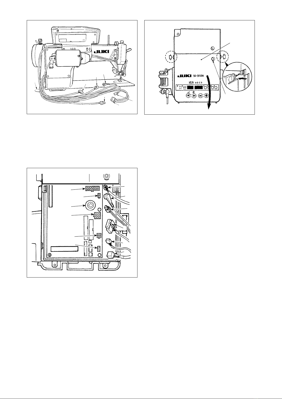
Following connectors are prepared on the front face of SC-910N. Connect the connectors coming from the
machine head to the corresponding places so as to t the devices mounted on the machine head.
1CN30 Synchronizer : it detects the needle bar
position.
2 CN35 CP-170 panel : Various kinds of
programmed sewing can be executed.
(Refer to the Instruction Manual for each
panel for the details of functions.)
3CN31 Machine head connector 4P
4CN42 External input/output connector : input/
output of up/down detection signal, rotation
prohibition signal, etc. is prepared.
5CN48 Safety switch (standard) : When tilting the
sewing machine without turning the power
OFF, the operation of the sewing machine is
prohibited so as to protect against danger.
Optional switch : by changing over the
internal functions, 6 kinds of functions can
be selected.
6CN40 Presser foot lifter solenoid. (For automatic
presser foot lifter type only)
7CN46
Machine head solenid : Thread trimming, reverse-
stitching solenoid, touch-back switch, etc.
8CN47 Optional circuit board connection connector
: Required when using JUKI standard
bobbin thread remaining amount detection
sensor, etc.
9CN39 Motor signal connector
!0 CN32 Standing machine pedal : JUKI standard
PK-70, etc. Sewing machine can be
controlled with the external signal.
!1CN34 IP-110 panel (LCD panel) : Various kinds of
programmed sewing can be executed.
!2 CN45 Material end detection sensor ED-5, etc.
!3 CN43 Fan
* By adding the optional unit A, the following optional
devices of JUKI standard can be connected.
1CN128 Left/right needle detection
2CN127 Thread holding, thread suction, thread
drawing
3CN122 Needle cooler (bottom fan)
4CN121 Bobbin thread remaining amount detection
5CN120 +24V external power source
6CN123 Needle/bobbin thread remaining amount
detection sensor
7CN125 External interface I/F D/A Input
8 CN126 Left/right lock SW, LED
9CN129 Thread holding, thread suction, thread
drawing, bobbin thread remaining amount
detection.
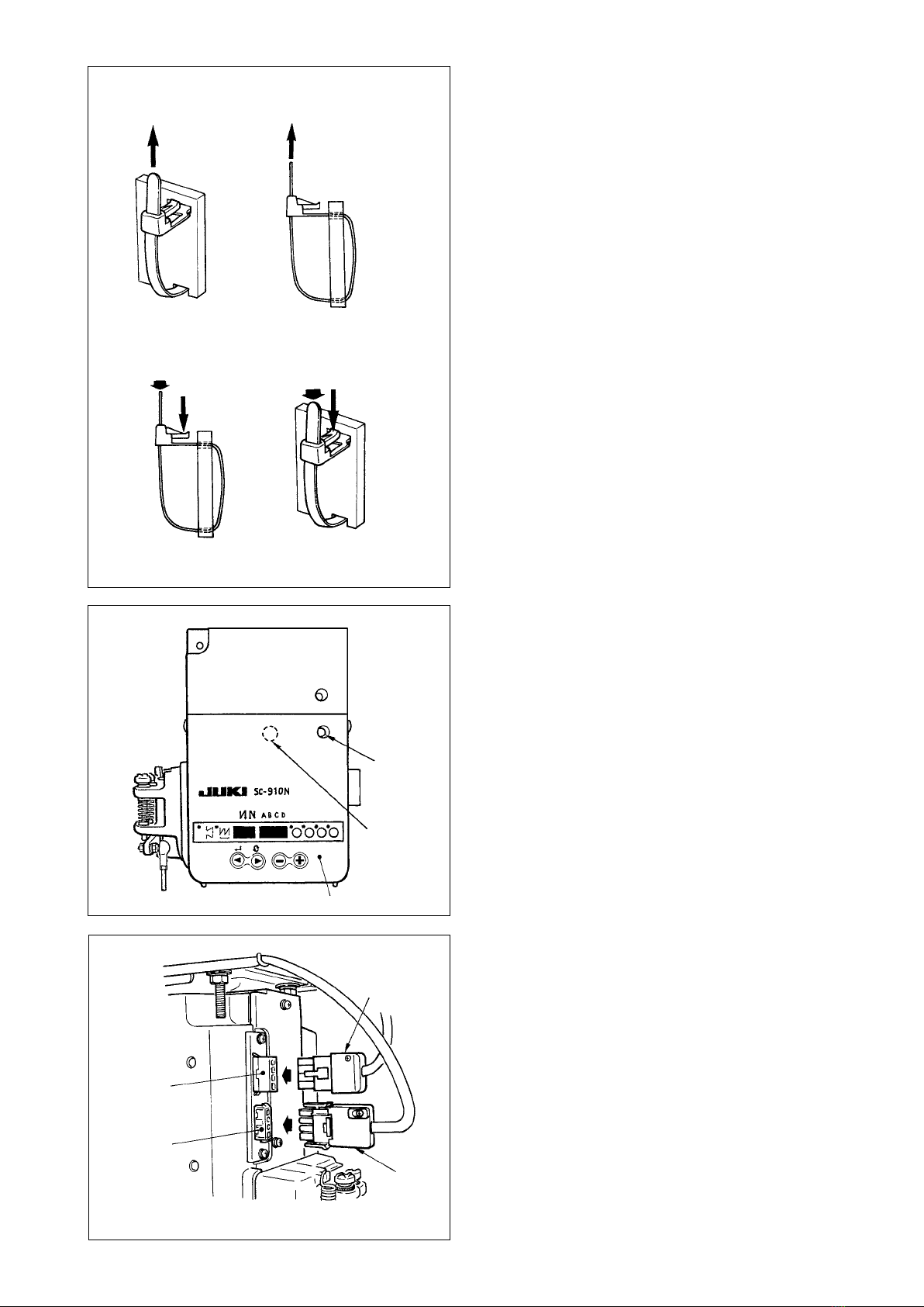
WARNING :
• To prevent personal injury caused by abrupt start of the sewing machine, carry out the work after
turning OFF the power switch and a lapse of 5 minutes or more.
• To prevent damage of device caused by maloperation and wrong specifications, be sure to
connectallthecorrespondingconnectorstothespeciedplaces.
• To prevent personal injury caused by maloperation, be sure to lock the connector with lock.
• As for the details of handling respective devices, read carefully the Instruction Manuals supplied
with the devices before handling the devices.
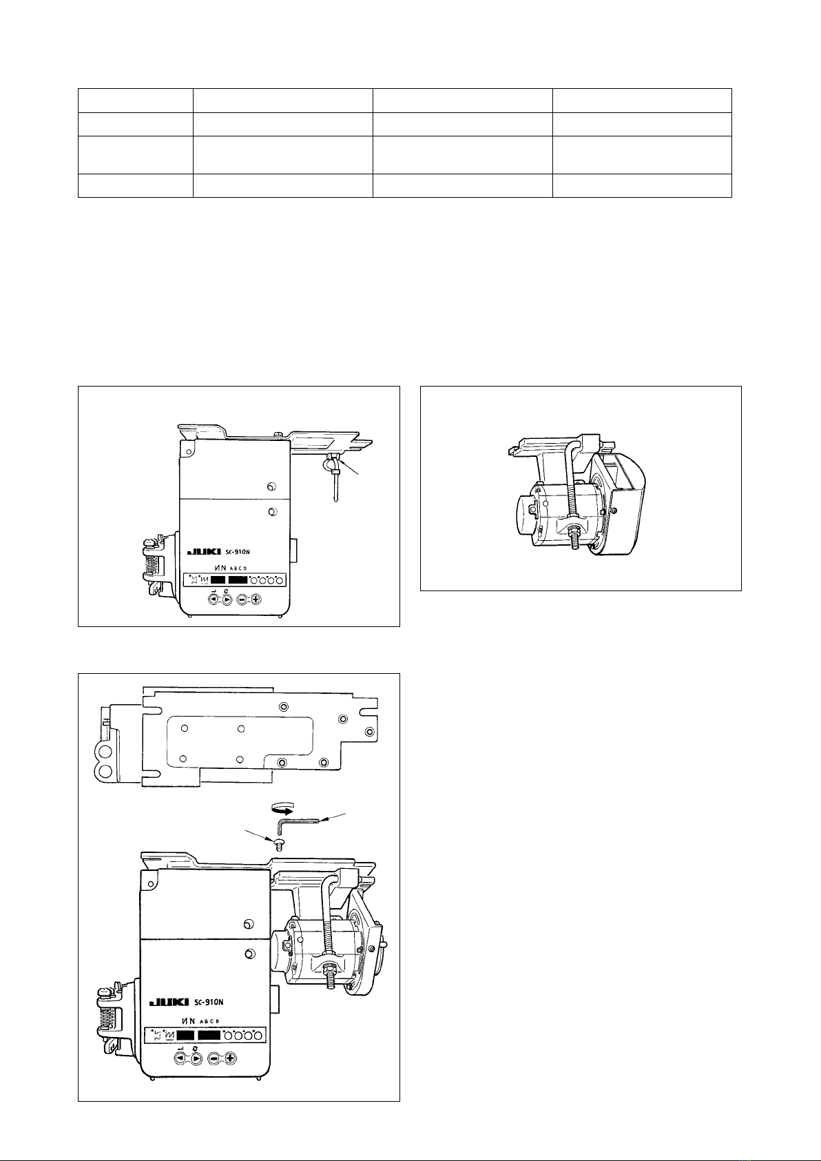
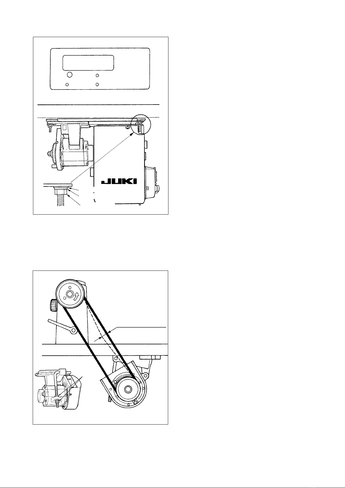
5. Connecting the cords
Optional unit A
1
2
3
4
5
6
7
8
9
1
7
2
6
3
4
5
9
!0
8
!2
!3
!1