manuals.online logo
Brands
  1. Home
  2. •
  3. Brands
  4. •
  5. JVC
  6. •
  7. Radio
  8. •
  9. JVC NIVICO 8500E User manual

JVC NIVICO 8500E User manual

5
5
mssza8
%nnnon
z
WZ
dcncncndcn
'?
b
n
(dm
2
nnnn
'0m-o-C
C
C
C
C
2
G G
G
.-.
2
OdN
dNCqc4+10WbWr3ddd
"~"~~P
E
E
E5
xxx xxxxxxxxx
ncl4mmm
NOTICE
The main difference between model 8500 and 8500E is of AC input voltage.
V30235
V11036 6 Pocket Cover
Plate V10561-2
Handle
VlOO10
Back Cover
53689-3
Antenna Jack Q03970-2
Jack
Ass'y
~30.234 V40180-6
Battery Cover Plate
Fig.
I
TO REMOVE
CHASSIS
1.
Remove five screws on the Back Cover.
2.
Open the Battery Cover pushing it downward and remove a screw on the battery case.
3. Remove eight screws on the bottom of the cabinet.
4.
Remove three front knobs and side knob.
5. Remove two nuts
"A"
as indicated in Fig. 2.
6.
Disconnect the white lead wire which is connected to the
rod
antenna.
7.
Pull up the rod antenna,
8.
Pull out the chassis from the right side.
Fig. 2
-2-
525KHz Standard L210
1
Maximum Capacity
1
l65OKHz
1
C209
Loop Antenna
1
Minimum Capacity
I
Repeat step 9,10
I
620KHz
/
Standard
1
L202,217
I
620KHz Signal
1
140KHz
Antenna
1
C206,216
I
1
1400KHz Signal
(
Repeat step 12,13
2. OMHz
1
Maximum Capacity
%
1
4. OMHz
1
Minimum Capacity
Repeat step 15,16
2. OMHz
1-
I
L203,218
1
2. OMHz Signal
%
--
I
4. OMHz C206,217
1
4.OMHz Signal
I
Repeat step 18,19
1
10.OMHz Signal
21
22
23
24
Repeat step 24,25
L213
I
Maximum Capacity
%
12.2MHz
ll.
5MHz
I
1
C212
1
Minimum Capacity
SW 3 Repeat step 27,28
1
1
11.8MHz
1
%
1
L205,220
1
11.8MHz Signal
SW 2
--
11
I/
21.6MHz
I
%
/
L208,223
I
21.6MHz Signal
%
Through Dummy Antenna (Fig. 5), connect to the white lead wire which is connected to rod antenna.
Note
:
For each band of SW3,4,5,6 the local oscillation frequency must be aligned lower than signal
4.6MHz
10.5MHz
L214
1
Maximum Capacity
%
1
C213
1
Minimum Capacity
31
I
I
14.9MHz
13b
frepuency by 455KHz, and when alignment of SW1,2,3,4,5,6, the rod antenna must be disconnected.
L212
1
Maximum Capacity
%
1
C2ll
1
Minimum Capacity
--
32
Repeat step 21,22
4.7MHz
I
1
L204,219
)
4.7MHz Signal
15.8MHz
SW 6
33
34
35
36
37
38
21. OMHz
22.3MHz
SW 4
SW 5
-
--
Repeat step 31,32
-
--
15.3MHz
%
I
L209,221
1
15.3MHz Signal
i
L216
1
Maximum Capacity
5%
-
1
C215
7
Minimum Capacity
17.3MHz
18.4MHz
--
pp
Repeat step 39,40
-
L215
/
Maximum Capacity
%
1
C214
1
Minimum Capacity
-
Repeat step 35,36
---
--
17.8MHz
1
%
I
L207,222
I
17.8MHz Signal
I
RI
I
R2
C
I
I
'
DUMMY
I
I
I
ANTENNA:
Fig. 5
4. FM IF Alignment
Volume Control
:
Minimum
1)
Connect the out clip of
T.
V. sweep generator's IF/RF OUTPUT lead to the local oscillator terminal
of
V.
Cap. and also the other clip to the earth.
2) Connect the scope terminal of
T.
V. sweep generator to H. input of oscilloscope, and also the ground
terminal to earth of the H. Input.
3) IF Alignment
(a) Give the output from emitter side of X8 to V. Input of oscilloscope.
(
b
)
Give the unmodulated 10.7MHz marker of S. S. G. to the set.
(
c
)
Align L105,106, 1,2so that the maximum sensitivity and symmetrical wave mode will be obtained,
setting the 10.7MHz marker on the peak.
4) Discriminator Alignment
(
a
)
Give the output from detector transformer to
V.
INPUT of oscilloscope.
(b) Give the 10.7MHz marker of 50-60 db output modulated to 30~60%by AM from S.S.G. to set.
(c
)
Align L4 so that the sign wave appearing on the flyback line of 'IS" curve will disappear.
(d) Align L3 so that the response of the "SNcurve will become maximum and symmetry.
5) Repeat that step 3), 4), and make sure that IF peak and center point of the "SNcurve will exactly
coincide with 10.7MHz marker.
5. FM RF Alignment
Volume Control
:
Maximum
Input Signal
:
Use 75Q terminal of S. S. G.
400Hz modulation, 22.5KHz deviation.
a
White lead wire which is connected to rod antenna.
-5-
Input
Frequency
1
It is given to Places to be aligned Position of
V.
Cap.
86.5MHz
2
I
109MHz
L103
1
Maximum Capacity
33
1
C103
I
Minimum Capacity
3
1
Repeat step 1.2
9OMHz
5
I
106MHz
6
1
Repeat step 4,s
33
L101,102
1
9OMHz Signal
C104,105
1
106MHz Signal
Parts No.
Capacitors
(203438-1
Q03667-5
QO3667-6
aQ03103-
sQ03104
sQ03105
sQ03106-
aQ03107-
sQ03108-
Q03246-103
Q03246-223
Q03246-333
Q03246-104
Q03263-331
Q03263-102
Q03263-152
Q03263-202
Q03263-322
Q03263-392
QO4062-1000
Q04062-5000
Q04062-01
Q04062-02
s46961-
%Q04305-
%Q04335-
Q00402-10CH
Q00402-150CH
Q04423-18PH
Q04223-24PH
Q04423-51PH
Note
:
When
unit is
pF
more than O.01pF and
PF
less than O.01pF) in addition to the head number.
The List
of
Main Parts
for
Replacement
--
Parts Name Symbol
I
Description
I
-
6V
t1Z%
6V
+I50% 1OV
-
10
:I;;% lOV
"3%
15V
il:$j 15V
-t-
20%
4
20%
4
20%
4
20%
-
+
5%
-
+
5%
5%
+-
5%
Variable Capacitor
Adjustable Capacitor
II
II
Electrolytic Capacitor
II
II
II
II
II
II
II
II
II II
Mylar Capacitor
II II
II II
II
II
Polystyrol Capacitor
II II
II II
II
II
II 11
ClOl-103,201-203
C104, 105,106
C2O-l-218
C41-43,45,39
C22,36
C32
C37,44,239
C49
C48
C224,225,236,245,246,46,74
C21
C16
C40
C238
C14,27
C231
C5
C237
II
11
Ceramic Capacitor
II
11
II
11
II
11
II
11
II
II
11 11
II
II
11
II
II II
N
I/
II II
C232
+
57b
C1,30,31
I?
5%
+
80
-
20%
C33
+
80
-
20%
C9,20,34,35,38, 108,109,110,119,120,
+
80%
123,124
-
20
C2,6,10,19,24,52
+
800,
-
20'0
C112,229,230
-
+
3%
C3, 11,23,25. 26,51,111, 112,113, 115,
4
10%
116,125,223,233,234,235,243,244,247
219,226
C7, 12,17,114,118,121
-
+-
5%
C117
4
5%
C229
4
5%
C240
4
5%
C221,228,242
+
5%
C220,227,241
4
5%
I
-
you request the capacitors marked with
s,
inscribe capacitance value (of which
Parts No.
Resistors
Q03862-1
Q04834-2
Q04850-1
Q04845-1
Q04802-
sQ04793-
sQ04092-
Q04802-4.7
Parts Name Symbol
1
Description
I
Note
:
When you request the resistors marked with
s,
inscribe resistance value in addition to
210% %W
210%
xw
-
+lo% 1W
210%
xw
I
Variable Resistor
11 11
11 11
11 11
Carbon Resistor
11 11
Composition Resistor
Carbon Resistor
LlOl
L224,225,226,227
L102
L103
L104
L201,202
L203
L204
L205
L206
L207
L208
L209
L210
L211
L212
L213
L214
L215
L216
L217
L218
L219
L220
L221
L222
L22.1
L105
L106, C119
L1,4, C4,13
L3
L4, C29
L5
L6, C8
L7, C15
the head
Coils
&
Transformers
VO3066-5
VO3047-14
VO3041-10
VO3041-20
03226-1
VO2001-68
03205-7
03205-8
03205-9
03203-10
03205-1 1
03205-12
03184-19
03184-20
03184-21
03184-28
03184-28
03184-29
03184-25
03184-30
031b5-6
03185-7
03185-8
03185-9
03185-10
03185-11
03185-12
03130-33
03130-34
03130-35
03130-41
03130-42
03064-48
03064-46
03064-47
R29, S9,10
R28
R102
R203
R1-16,31-40,101-110,201,202,204-210
R17,30,41,46, 211,212,213,214
R44,45
R43
number.
Antenna Coil (FM)
Antenna Coil (Trap)
RF Coil (FM)
Oscillator Coil (FM)
IF Trap Coil
Bar Antenna Ass'y
Antenna Coil (SW1)
11 11
(SW2)
11 11
(SW3)
I/
/I
(SW4)
11 I/
(SW5)
11 11
(SW6)
Oscillator Coil (LW)
11 I/
(MW)
I/ /I
(SW1)
I/ I/
(SW2)
I/ 11
(SW3)
I/ 11
(SW4)
11 11
(SW5)
I/ 11
(SW6)
RF Coil (M
W)
/I 11
(SWl)
I/ 11
(SW2)
11 11
(SW3)
11 11
(SW4)
11 11
(SW5)
/I 11
(SWE)
I.
F.T. (FM 1st)
11 11
11
(FM 2nd
&
3rd)
11
(FM Det.)
11 11
11
(AM 1st)
/I I/
11
(AM 2nd)
Reauirement to Customers
For the purpose of prompt supply of service parts, inscribe parts number,
parts name, and model name correctly when you order.
0
If possible please give an order for spare cabinet in early opportunity
since it is very difficult to remanufacture cabinet case after production of
the set was discontinued.
Description
Parts No.
I
Parts Name
03064-46
1
I.
F.
T.
03064-49
11
(AM, 3rd)
03079-8 Input Transformer
03096-22 Output Transformer
03218-16 Power Transformer
Speaker
SK-2055B 4"
x
6" Speaker
Jack
&
Plug
Q03948-1 Earphone Jack Ass'y
41537-E Jack Ass'y
Symbol
--
L8, C18
L8, C28
T1
T2
T3
J3,
4
J2
A03004-H
53689-3
Power Cord with Plug
I
I
Antenna Jack
I
J1
I
(Note
:
-4s to cabinet parts, refer to the picture in front page.)
Switches
I
I
Q03746-2 Slide Switch
I
S8
S1--7
V20280-B Rotary Switch Ass'y
Dial
Parts
V41040-B Needle Ass'y (Band)
V41041-B
11
N
(Tuning)
903989-A Dial Drum Ass1y (Band)
V40030-A
VO3020-3
Q04967-2
11
N
11
(Tuning)
Tuning Indicator
Pilot Lamp
Q30110-A P. Lamp Socket Ass'y
Others
V40354-A
'
Rod Antenna
47380-C Antenna Tip

Other JVC Radio manuals

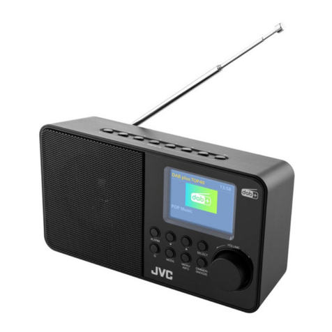
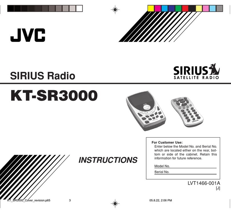
JVC Sirius KT-SR3000 User manual

JVC

JVC Sirius KT-SR3000 User manual

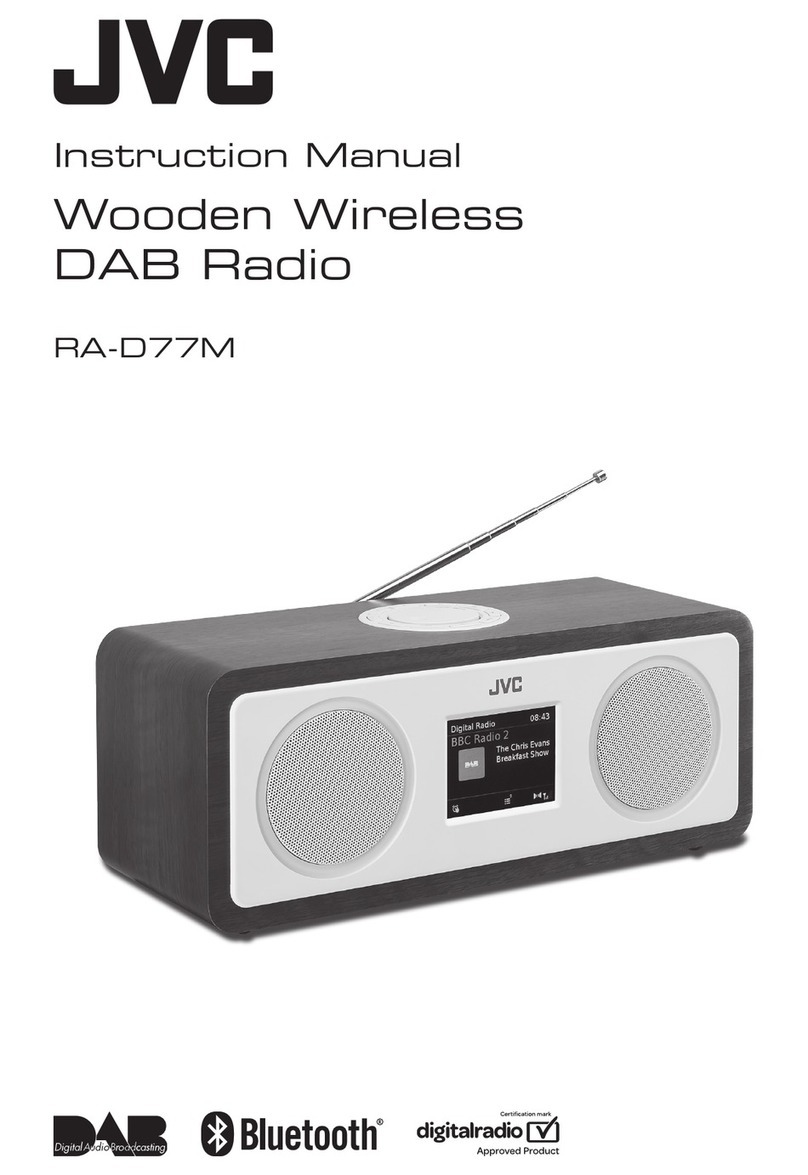
JVC RA-D77M User manual

JVC

JVC RA-D77M User manual

JVC KT-HDP1 - HD Radio Tuner User manual

JVC

JVC KT-HDP1 - HD Radio Tuner User manual

JVC KT-HD300 - Add-On HD Radio Tuner Works User manual

JVC

JVC KT-HD300 - Add-On HD Radio Tuner Works User manual

JVC RA-E431B User manual

JVC

JVC RA-E431B User manual

JVC RA-E611B-DAB User manual

JVC

JVC RA-E611B-DAB User manual

JVC FR-DS100 User manual

JVC

JVC FR-DS100 User manual

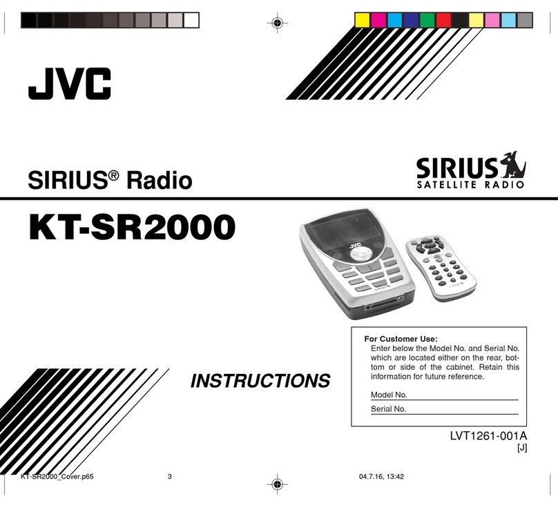
JVC KT-SR2000 - Sirius Satellite Radio Tuner User manual

JVC

JVC KT-SR2000 - Sirius Satellite Radio Tuner User manual

JVC KT-SR1000 User manual

JVC

JVC KT-SR1000 User manual

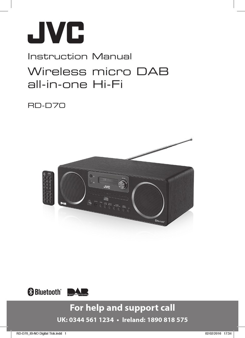
JVC RD-D70 User manual

JVC

JVC RD-D70 User manual

JVC RA-D58B User manual

JVC

JVC RA-D58B User manual

JVC RA-E731B-DAB User manual

JVC

JVC RA-E731B-DAB User manual

JVC RA-E411B User manual

JVC

JVC RA-E411B User manual

JVC RA-D51 User manual

JVC

JVC RA-D51 User manual

JVC KT-HDP1 - HD Radio Tuner Operation manual

JVC

JVC KT-HDP1 - HD Radio Tuner Operation manual

JVC RA-D58B User manual

JVC

JVC RA-D58B User manual

Popular Radio manuals by other brands

Sangean DT-200VX Specification sheet

Sangean

Sangean DT-200VX Specification sheet

Blaupunkt PP15DAB owner's manual

Blaupunkt

Blaupunkt PP15DAB owner's manual

auna multimedia 10027024 manual

auna multimedia

auna multimedia 10027024 manual

LENCO 8711902066156 user manual

LENCO

LENCO 8711902066156 user manual

Tivoli Audio NetWorks Speaker owner's manual

Tivoli Audio

Tivoli Audio NetWorks Speaker owner's manual

Milwaukee 2790-20 Operator's manual

Milwaukee

Milwaukee 2790-20 Operator's manual

Hyundai RTC 1028 RIP instruction manual

Hyundai

Hyundai RTC 1028 RIP instruction manual

Medion MD 44100 user manual

Medion

Medion MD 44100 user manual

Alcatel-Lucent 9500 MPR user manual

Alcatel-Lucent

Alcatel-Lucent 9500 MPR user manual

SOUNDMASTER Highline TR-18 USB manual

SOUNDMASTER

SOUNDMASTER Highline TR-18 USB manual

E.F. Johnson Company 5300 ES Series operating manual

E.F. Johnson Company

E.F. Johnson Company 5300 ES Series operating manual

Radioddity DB25-D extended manual

Radioddity

Radioddity DB25-D extended manual

Midland GXT760 series manual

Midland

Midland GXT760 series manual

Imperial DABMAN i500 quick start guide

Imperial

Imperial DABMAN i500 quick start guide

Panasonic RF-2400 Service manual

Panasonic

Panasonic RF-2400 Service manual

Audiovox Sirius SIR-PNP3 user guide

Audiovox

Audiovox Sirius SIR-PNP3 user guide

nedis RDFM5000BN manual

nedis

nedis RDFM5000BN manual

Trevi RC 832 user guide

Trevi

Trevi RC 832 user guide

manuals.online logo
manuals.online logoBrands
  • About & Mission
  • Contact us
  • Privacy Policy
  • Terms and Conditions

Copyright 2025 Manuals.Online. All Rights Reserved.