manuals.online logo
Brands
  1. Home
  2. •
  3. Brands
  4. •
  5. Kärcher
  6. •
  7. Scrubber
  8. •
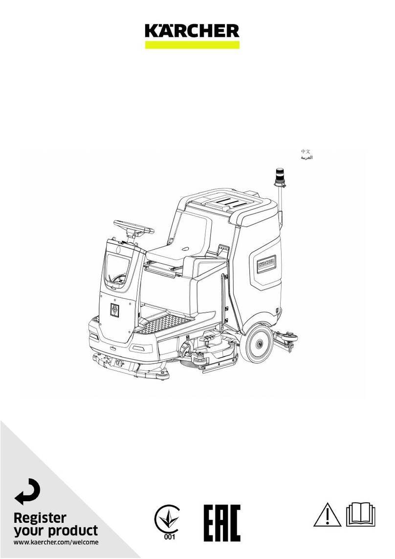
  9. Kärcher BR 75/140 R Series Owner's manual

Kärcher BR 75/140 R Series Owner's manual

New Unit Information 03.2004
BR/BD 75/140 R
BR/BD 90/140 R
1.246- . . .
New Unit Information
5.905-888
Technical Features BR/BD 75/140 R, BR/BD 90/140 R
Page 2 / 71 New Unit Information 03.2004
Drive unit system
– 3-wheel running gear with front wheel steering
and front wheel-hub motor with electro-magne-
tic brake.
– Forwards and reverse drive unit with one drive
pedal, changeover with selector button on the
instrument panel.
– Machine brakes automatically, if the driver
moves away (removes weight) from the seat
(seat contact switch) or if the drive pedal is
released. The brake function takes place with
approx. 1.5 seconds delay.
– When not in operation, an electromagnetic
brake on the wheel-hub motor prevents the
unit from rolling away.
Brush system
– Brush head with two brush rollers or two disc
brushes (two drive motors each).
– Brush rollers rotate from below towards; each
other disc brushes rotate together at the front.
– Coarse dirt pan for coarse dirt picked up at the
brush head (BR version only).
– Brush head contact pressure is adjustable.
– Brushes can be changed without tools.
– Brush head with lateral sealing strips to limit
water distribution.
Water system
– Fresh-water tank in the front of the unit hou-
sing.
– Dirty water tank at the rear with float switch.
– Water feed to brush head with water pump.
– Water flow control with electric metering val-
ve, 10 positions.
– Air bleeder valve for quick bleeding of the wa-
ter hose at the brush head (only BR head).
Vacuum system
– Suction motor (long life) vacuums the dirty
water into the dirty water tank.
– If the dirty water tank is full the electric float
switch switches off the suction motor with a
time delay between 15-20 seconds.
– Suction bar available in a straight or curved
version.
– On switching the suction motor On/Off the
suction bar is lowered/raised. When raised the
suction motor continues running for approx.
10 seconds.
– Rubber strips on the suction bar can be repla-
ced without tools.
– The inclination of the suction bar can be adju-
sted without tools.
Electrics
– The main control printed circuit board is loca-
ted behind the metal cover to the left next to the
footrest.
– The instrument panel printed circuit board is
located underneath the control panel.
Battery
– 24 Volt block battery, 400 Ah, low-maintenance
with filling system.
– Battery monitoring with exhaustive discharge
protection.
Note:
Various things have been changed in the
version of the unit. They are
identified in this document with .
The most important change concerns the
new printed circuit board 2.816-067, which
will be installed as of manufacturing number
10800.
REVISED
REVISED
BR/BD 75/140 R, BR/BD 90/140 R Unit Functions
Page 3 / 71
New Unit Information 03.2004
1 Steering wheel
2 Control panel
3 Cap, fresh-water tank
4 Fresh-water tank
5 Cover, main control printed circuit board
6 Central battery connector (X1)
7 Drive unit pedal
8 Front wheel, wheel hub motor
9 Lateral sealing strip, spring-loaded
10 Brush head, BR version
11 Coarse dirt pan (BR version only)
12 Seat
View from front (BR-Version)
1
3
4
6
7
8
9
12
2
5
10
11
Page 4 / 71
Unit Functions BR/BD 75/140 R, BR/BD 90/140 R
New Unit Information 03.2004
1
3
2
4
6
7
8
9
10
11
12
1 Cover, main control printed circuit board
2 Brush head, BR version
3 Lateral sealing strip, spring-loaded
4 Coarse dirt pan (BR version only)
5 Supporting castor for suction bar, optional
6 Suction bar, straight version
7 Deflector wheel, suction bar
8 Drain hose, dirty water tank
9 Suction hose
10 Dirty water tank
11 Cover, dirty water tank
12 Control panel
View from rear (BR-Version)
5
BR/BD 75/140 R, BR/BD 90/140 R Unit Functions
Page 5 / 71
New Unit Information 03.2004
Suction bar
1 Drain hose, dirty water tank
2 Suction hose
3 Deflector wheel with star handle for
replacing/rotating the rubber strips
4 Star handle, for installing the suction bar
5 Rubber strip
6 Wing nut, for adjustment of suction bar
inclination
7 Bracket, suction bar
8 Lifting motor (M30) for lowering and
raising the suction bar
Note:
As a standard, the front rubber strip is
grooved and the rear one is smooth. In case
of wear, both rubber strips can be rotated to
extend their application life.
1
8
6
7
5
4
3
2
Page 6 / 71
Unit Functions BR/BD 75/140 R, BR/BD 90/140 R
New Unit Information 03.2004
1 Tank cover
2 Fluff strainer, air intake suction motor
3 Float switch (S17)
4 Seal, tank cover
Dirty water tank
1
2
4
3
BR/BD 75/140 R, BR/BD 90/140 R Unit Functions
Page 7 / 71
New Unit Information 03.2004
Brush head (BR-Version)
1 Brush head (BR version)
2 Front wing nut, for securing the mounting
plate
3 Deflector wheel
4 Spring for lateral sealing strip mounting
plate
5 Lateral sealing strip
6 Mounting plate for sealing strip, spring-
loaded
7 Adjusting screw, brush pattern
8 Rear wing nut, for securing the mounting
plate
9 Cover for brush drive unit assembly
1
2
3
45
6
7
8
9
Page 8 / 71
Unit Functions BR/BD 75/140 R, BR/BD 90/140 R
New Unit Information 03.2004
Brush head (BD-Version)
1 Brush head (BD version)
2 Deflector roller
3 Disc brush
4 Side sealing strip, spring loaded
5 Brush head bracket
1
2
3
4
5
BR/BD 75/140 R, BR/BD 90/140 R Unit Functions
Page 9 / 71
New Unit Information 03.2004
1 Connecting terminal minus pole
2 Connecting terminal plus pole
3 Connection cable
4 Battery (G1)
5 Central battery connector (X1)
= EMERGENCY STOP
6 Air outlet hose, suction motor
7 Suction motor (M3, EC long life)
8 Dirty water tank
Battery
–
1
2
3
4
5
6
7
8
+
Note:
The dirty water tank (8) can only be lifted if
the dirty water has been drained.
ORIGINAL
Page 10 / 71
Unit Functions BR/BD 75/140 R, BR/BD 90/140 R
New Unit Information 03.2004
1 Connecting terminal minus pole
2 Connecting terminal plus pole
3 Connection cable
4 Battery (G1)
5 Central connector (X1) = EMERGENCY
STOP
6 Filling hose
7 Suction motor (M3, EC long life)
8 Dirty water tank
Battery
1
2
3
5
4
8
7
6
REVISED
Note:
The dirty water tank (8) can only be lifted if
the dirty water has been drained.
BR/BD 75/140 R, BR/BD 90/140 R Unit Functions
Page 11 / 71
New Unit Information 03.2004
Central battery connector
1 Connection cable from the block battery
2 Connection cable (auxiliary contact S32)
to the control panel
to the main control printed
circuit board
3 Connection cable with the main control
printed circuit board (A1)
4 Central connector (X1) - lower section
5 Central connector (X1) - upper section
with handle
EMERGENCY STOP function
All the unit’s electrical components are connec-
ted to the block battery via the central connector.
If the upper section (5) is pulled off, the whole unit
becomes isolated and the electromagnetic bra-
ke is activated in the front wheel and the unit is
braked.
4
1
5
and
ORIGINAL
REVISED
Note:
An external battery charger is connected to
the central connector-upper section (5).
2
3
ORIGINAL
REVISED
Page 12 / 71
Unit Functions BR/BD 75/140 R, BR/BD 90/140 R
New Unit Information 03.2004
Battery charger
1 Central connector (X1) - upper section
with handle
2 Plug for connection with the battery
charger
3 Battery charger
4 Central connector (X1) - lower section
5 Mains cable, battery charger
1
2
3
4
5
BR/BD 75/140 R, BR/BD 90/140 R Unit Functions
Page 13 / 71
New Unit Information 03.2004
Control panel
1
2
3
4
5
6
7
8
9
10
11
12
13
14
15
16
17
18
19
20
21
22
23
24
25
26
27
28
29
and
ORIGINAL
REVISED
Page 14 / 71
Unit Functions BR/BD 75/140 R, BR/BD 90/140 R
New Unit Information 03.2004
Control panel (up to software version 2.5)
ORIGINAL
Item Name Function
1 Indicator light (green) Lights up when warning beacon light is switched on.
2 Indicator light (green) Lights up if working lights are switched on.
3 "Working light" push-button
(optional)
Switches working light ON/OFF.
4 "Warning beacon light" button
(optional)
Switches warning beacon light ON/OFF.
5 Indicator light (red) Lights up if brush pressure too high, brushes are
switched off after 4 sec.
6 Indicator light (red) Lights up if dirty water tank is full.
Suction motor switches off after approx. 15 sec.
7 "Suction motor" push-button – Switches the suction motor ON/OFF and
simultaneously lowers/ raises the suction bar.
– Suction motor continues to run for approx.
10 sec after being switched off.
8 "Increase brush pressure" push-
button
Increases the brush pressure.
9 "Brush motor" push-button Activates the brush motors.
The brush motors only start up if the drive pedal is
pressed.
10 Indicator light (green) – Flashes if brush motors are activated.
– Lights up if brush motors are running.
11 "Reduce brush pressure" push
button
Reduces the brush pressure.
12 "Memo" push-button Starts/ends pre-selected functions of brush motors,
suction motor, water pump.
13 "Forward drive" push-button Activates forward movement.
14 Indicator light (green) Lights up if forward movement is activated.
15 Indicator light (green) Lights up if reverse movement is activated.
16 "Horn" push-button Acoustic alarm sound signal.
17 "Reverse drive" push-button Activates reverse movement.
18 Key switch Activates the unit's power supply.
19 "Info" push-button Shown in display:
– Current operating voltage.
– Hours-run meter (hh.mm).
As soon as the operating hours counter starts a
"+" symbol appears behind the minute display.
20 "Reduce water flow" push-button Reduces the quantity of water by adjusting the
metering valve.
BR/BD 75/140 R, BR/BD 90/140 R Unit Functions
Page 15 / 71
New Unit Information 03.2004
Control panel (up to software version 2.5)
ORIGINAL
Item Name Function
21 Indicator light (green) – Flashes if water function is activated.
– Lights up if water pump is running and metering
valve is open.
22 "Water pump" push-button Activates water pump and metering valve.
The water pump does not start unless the drive
pedal has first been pressed and the brush
motors are activated.
23 Display 2-line, 16 characters/line.
24 "Increase water flow" push-button Increases the quantity of water by adjusting the
metering valve.
25 Indicator light (green) – Lights up if suction motor is running.
– Flashes during the after-running time.
26 Indicator light (red) Lights up if magnet brake is activated.
27 Indicator light (red) – Flashes, if battery voltage has fallen to 1 Volt
above the set end-point voltage. In addition,
a one-time acoustic alarm signals.
– Lights up, if battery voltage has dropped below
the deep-discharge protection voltage.
28 "Wall-Floor-Ceiling Nozzle" push-
button
Switches water pump and suction motor on for
wall-ceiling-floor nozzle. Function can only be
selected when unit is at a standstill.
29 Indicator light (green) Lights up if push-button 28 is activated.
– Drive pedal, forward drive If the drive pedal is pressed the following
functions are activated (if pre-selected):
– Brush motors are switched on.
– Brush head lowers.
– Suction motor is switched on.
– Suction bar lowers.
– Water pump is switched on.
– Metering valve opens.
– Indicator lights (10), (14), (21) and (25)
continuously light up.
Note: The suction motor remains active
irrespective of the drive pedal.
– Drive pedal, reverse drive If the drive pedal is pressed the following
functions are activated (if pre-selected):
– Suction bar rises.
– Indicator lights (10), (15), (21), (25) continuously
light up.
– Acoustic alarm sound signal.
Note: The suction motor remains active
irrespective of the drive pedal.
Page 16 / 71
Unit Functions BR/BD 75/140 R, BR/BD 90/140 R
New Unit Information 03.2004
Control panel (from display software version V1.0)
REVISED
Item Name Function
1 Indicator light (green) Lights up when warning beacon light is switched on.
2 Indicator light (green) Lights up if working lights are switched on.
3 "Working light" push-button
(optional)
Switches working light ON/OFF.
4 "Warning beacon light" button
(optional)
Switches warning beacon light ON/OFF.
5 Indicator light (red) Lights up if brush pressure too high, brushes are
switched off after 4 sec.
6 Indicator light (red) Lights up if dirty water tank is full.
The suction motor switches off after approx. 15 sec.
If "empty" is recognised again, the LED continues to
flash for one minute. During this time period it is not
possible to switch on the suction motor using the
"memo" function or the Wall-Floor-Ceiling-Nozzle
function.
7 "Suction motor" push-button – Switches the suction motor ON/OFF and
simultaneously lowers/ raises the suction bar.
– Suction motor continues to run for approx.
10 sec after being switched off.
8 "Increase brush pressure" push-
button
Increases the brush pressure.
9 "Brush motor" push-button Activates the brush motors.
The brush motors only start up if the drive pedal is
pressed.
10 Indicator light (green) – Flashes if brush motors are activated.
– Lights up if brush motors are running.
11 "Reduce brush pressure" push
button
Reduces the brush pressure.
12 "Memo" push-button Starts/terminates preselected brush motor, suction
motor and water pump functions and automatically
switches the components ON/OFF at defined time
intervals.
13 "Forward drive" push-button Activates forward movement.
14 Indicator light (green) Lights up if forward movement is activated.
15 Indicator light (green) Lights up if reverse movement is activated.
16 "Horn" push-button Acoustic alarm sound signal.
17 "Reverse drive" push-button Activates reverse movement.
18 Key switch Activates the unit's power supply.
BR/BD 75/140 R, BR/BD 90/140 R Unit Functions
Page 17 / 71
New Unit Information 03.2004
Control panel (from display software version V1.0)
REVISED
Item Name Function
19 "Info" push-button Appears on the display:
– Battery status (bar diagram).
– Temperature of the main control printed circuit
board.
– Drive motor temperature (bar diagram).
– Version numbers of the individual micro
controllers.
– Type of floor cleaner.
20 "Reduce water flow" push-button Reduces the quantity of water by adjusting the
metering valve.
21 Indicator light (green) – Flashes if water function is activated.
– Lights up if water pump is running and metering
valve is open.
22 "Water pump" push-button Activates water pump and metering valve.
The water pump does not start unless the drive
pedal has first been pressed and the brush
motors are activated.
23 Display 2-line, 16 characters/line.
24 "Increase water flow" push-button Increases the quantity of water by adjusting the
metering valve.
25 Indicator light (green) – Lights up if suction motor is running.
– Flashes during the after-running time.
26 Indicator light (red) Lights up if magnet brake is activated.
27 Indicator light (red) – Flashes, if battery voltage has fallen to 1 Volt
above the set end-point voltage. In addition,
a one-time acoustic alarm signals.
– Lights up, if battery voltage has dropped below
the deep-discharge protection voltage.
28 "Wall-Floor-Ceiling Nozzle" push-
button
Switches water pump and suction motor on for
wall-floor-ceiling nozzle. Function can only be
selected when unit is at a standstill.
Page 18 / 71
Unit Functions BR/BD 75/140 R, BR/BD 90/140 R
New Unit Information 03.2004
Control panel (from display software version V1.0)
REVISED
Item Name Function
29 Indicator light (green) Lights up if push-button 28 is activated.
– Drive pedal, forward drive When the drive pedal is pressed the following
functions are activated (if pre-selected):
– Brush motors are switched on.
– Brush head lowers.
– Suction bar lowers.
– Water pump is switched on.
– Metering valve opens.
– Indicator lights (10), (14), (21) and (25)
continuously light up.
Note: The suction motor remains active
irrespective of the drive pedal!
– Drive pedal, reverse drive When the drive pedal is pressed the following
functions are activated (if pre-selected):
– Suction bar rises.
– Indicator lights (10), (15), (21), (25) continuously
light up.
– Acoustic alarm sound signal.
– When in pre-set of the Setup menu the warning
beacon light switches on during reverse drive.
Note: The suction motor remains active
irrespective of the drive pedal!
BR/BD 75/140 R, BR/BD 90/140 R Unit Functions
Page 19 / 71
New Unit Information 03.2004
Control panel printed ciruit board, view reverse side
1 Connection cable, to main control printed
circuit board
2 Control panel printed circuit board (A2)
3 Key switch (S1)
4 Flat cable, connection to plastic foil con-
trol panel
1
2
3
4
ORIGINAL
Page 20 / 71
Unit Functions BR/BD 75/140 R, BR/BD 90/140 R
New Unit Information 03.2004
Control panel printed ciruit board, view reverse side
1 Connection cable, to main control printed
circuit board
2 Control panel printed circuit board (A2)
3 Key switch (S1)
4 Flat cable, connection to plastic foil con-
trol panel
3
1
2
4
REVISED

This manual suits for next models

19

Other Kärcher Scrubber manuals

Kärcher BD 50/70 R Bp Classic User manual

Kärcher

Kärcher BD 50/70 R Bp Classic User manual

Kärcher B 260 User manual

Kärcher

Kärcher B 260 User manual

Kärcher BD 50/70 R Classic Bp Pack 80Ah Li User manual

Kärcher

Kärcher BD 50/70 R Classic Bp Pack 80Ah Li User manual

Kärcher BD Trike BAT User manual

Kärcher

Kärcher BD Trike BAT User manual

Kärcher B 60/10 C User manual

Kärcher

Kärcher B 60/10 C User manual

Kärcher BR 4.300 User manual

Kärcher

Kärcher BR 4.300 User manual

Kärcher CS26 LI User manual

Kärcher

Kärcher CS26 LI User manual

Kärcher Windsor Chariot 2 iScrub 20 User manual

Kärcher

Kärcher Windsor Chariot 2 iScrub 20 User manual

Kärcher BD 70/75 W Classic Bp User manual

Kärcher

Kärcher BD 70/75 W Classic Bp User manual

Kärcher BDS 43/150 C Classic User manual

Kärcher

Kärcher BDS 43/150 C Classic User manual

Kärcher VP6 User manual

Kärcher

Kärcher VP6 User manual

Kärcher KIRA B 50 User manual

Kärcher

Kärcher KIRA B 50 User manual

Kärcher BR 45/22 C User manual

Kärcher

Kärcher BR 45/22 C User manual

Kärcher Windsor Chariot 3 iScrub 26 User manual

Kärcher

Kärcher Windsor Chariot 3 iScrub 26 User manual

Kärcher BD 70/75 W Classic Bp Pack 80 Ah Li User manual

Kärcher

Kärcher BD 70/75 W Classic Bp Pack 80 Ah Li User manual

Kärcher BD 75/120 R Classic Bp User manual

Kärcher

Kärcher BD 75/120 R Classic Bp User manual

Kärcher BD 43/25 C Bp User manual

Kärcher

Kärcher BD 43/25 C Bp User manual

Kärcher BD 40/12 C User manual

Kärcher

Kärcher BD 40/12 C User manual

Kärcher HD 9/20-4 S User manual

Kärcher

Kärcher HD 9/20-4 S User manual

Kärcher BDS 33/190 C User manual

Kärcher

Kärcher BDS 33/190 C User manual

Kärcher BR 100/250 User manual

Kärcher

Kärcher BR 100/250 User manual

Kärcher B 300 RI D User manual

Kärcher

Kärcher B 300 RI D User manual

Kärcher B 150 R User manual

Kärcher

Kärcher B 150 R User manual

Kärcher KM 85/50 R Bp User manual

Kärcher

Kärcher KM 85/50 R Bp User manual

Popular Scrubber manuals by other brands

Powr-Flite PX1300 series Operators manual and parts lists

Powr-Flite

Powr-Flite PX1300 series Operators manual and parts lists

Nederman MagnaTrack HS Original user manual

Nederman

Nederman MagnaTrack HS Original user manual

Abicor Binzel FEC Operating	 instruction

Abicor Binzel

Abicor Binzel FEC Operating instruction

Weller Zero Smog TL Translation of the original instructions

Weller

Weller Zero Smog TL Translation of the original instructions

Triple S Ultron 18BA owner's manual

Triple S

Triple S Ultron 18BA owner's manual

Ewbank FP1000 Care and use instructions

Ewbank

Ewbank FP1000 Care and use instructions

Hakko Electronics FA-400 quick start guide

Hakko Electronics

Hakko Electronics FA-400 quick start guide

Tornado Floorkeeper 28 TD/99128D Operation & maintenance manual

Tornado

Tornado Floorkeeper 28 TD/99128D Operation & maintenance manual

Viper AS380/15B-AU user manual

Viper

Viper AS380/15B-AU user manual

Comet Spa CPS 36 ADVANCE instructions

Comet Spa

Comet Spa CPS 36 ADVANCE instructions

COMAC C130B manual

COMAC

COMAC C130B manual

Powr-Flite Predator Automatic Scrubber 40 PAS40R Operators manual and parts lists

Powr-Flite

Powr-Flite Predator Automatic Scrubber 40 PAS40R Operators manual and parts lists

Matrix CHF611 Manual for installation, use and maintenance

Matrix

Matrix CHF611 Manual for installation, use and maintenance

Ankom XT10 Operator's manual

Ankom

Ankom XT10 Operator's manual

Electrolux Professional Clarus WH6-8CV installation manual

Electrolux Professional

Electrolux Professional Clarus WH6-8CV installation manual

Nikro PS600 instruction manual

Nikro

Nikro PS600 instruction manual

Pacific Floorcare S-24 Parts & operating manual

Pacific Floorcare

Pacific Floorcare S-24 Parts & operating manual

Pts EUREKA E81 Operator's guide

Pts

Pts EUREKA E81 Operator's guide

manuals.online logo
manuals.online logoBrands
  • About & Mission
  • Contact us
  • Privacy Policy
  • Terms and Conditions

Copyright 2025 Manuals.Online. All Rights Reserved.