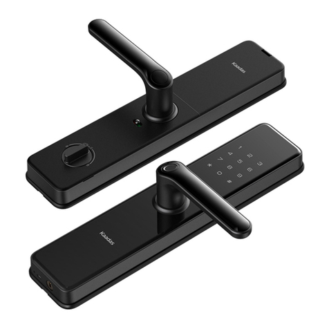
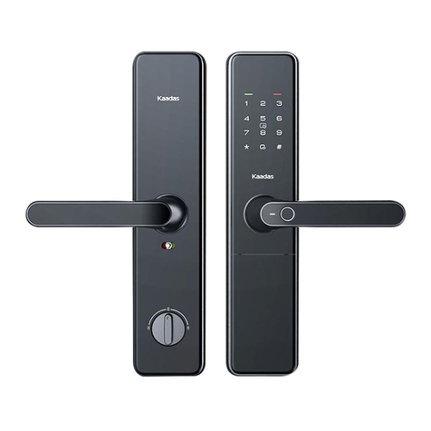
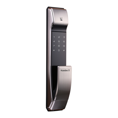
Kaadas K8-T User manual

K8-T
User Manual
www.kaadasgroup.com

This section contains important information to ensure the user's safety and
prevent potential damage to property. Please, read this section carefully and use
the product accordingly.
1CAUTIONS
1. Master PIN Code: Default Master PIN code is [12345678],please modify it immediately.
2. User PIN Code: It can be 6~12 digits number. You can register and up to 10 users.
3. Card: It is optional. Maximum capacity is 100 with user number [00-99].
4. Fingerprint: Maximum capacity is 100 with user number [00-99]
5. Be sure to correctly match the poles (+/-) when installing the batteries. Install the batteries
with the correct poles (+/-).
6. Replace all batteries immediately after they run out of power, and never mix new batteries
with used ones.
CAUTION
User Number User Type
Notes
00 - 04 Normal User
* Permanent
05 - 08
Temporary User * Invalid after using one time or in safety mode
09
Duress User
* Working with wireless module when duress event occurs
Overview
Outside escutcheon Inside escutcheon
Safe handle
switch
Battery cover
Close/Open
button
Touch
keypad
Fingerprint
sensor
Card reader
area
Push pull
handle Push pull
handle
Bottom of outside
escutcheon
Mechanical key hole
Reboot button
Emergency power USB port

Lock body
Mechanical key
Deadbolt
Sensor latch
Latch
Shaft socket
bolt
Pictures of components above are just reference, please refer to the material object.
CAUTION

2 keys
2
Number Item name Quantity
Lock body
Inside escutcheon
Outside escutcheon
1
2
3
4
5
6
7
8
9
10
11
Remark
1
1
1
User manual
1
1
1
1
1
Screw pack
Warranty card
1
Key box
1
Strike plate and dust cover
Installation template
Mounting plate
2
RFID Card
Package C ontent and E xplos ive V iew
This described package content is for reference only, the real products should be
considered as final. If some components lost, please check with the sellers.
1. Battery cover (1 pc)
2. M6 upper connecting mounting screw (1 pc)
3. Inside escutcheon assembly (1 pc)
4. Square shaft (2 pcs)
5. M5 mounting plate screw (4 pcs)
6. Mortise lock (1 pc)
7. Mounting screw (4 pcs)
8. M5 connecting screw bolt (4 pcs)
9. M6 upper connecting screw bolt (1 pc)
10. Pressure spring (1 pc)
11. Outside escutcheon assembly (1 pc)
12. Mounting plate (1 pc)
13. M6 bottom mounting screw (1 pc)
14. Bottom cover (1 pc)

3Before Installation
Confirm open direction
This product can be installed on left-in, left-out,right-in, and right-out doors.
3.1
Change open direction
Please change position of screws according to open direction.
1.Please choose correct screw pack according to your door thickness.
2.Default screw pack is for door thickness 38-60mm, please contact our dealer if other
screw pack required.
Left-out
Right-out
Left-inRight-in
Inside escutcheon
Screw
Screw
Screw
Screw
Screw
Screw
Screw
Screw
Inside escutcheon Inside escutcheon
Inside escutcheon
3.2
Left opening
In door
Out door
In door
Out door
Left-in
Left-out
Right opening
In door
Out door
In door
Out door
Right-in
Right-out
CAUTION

Drill holes according to the installation
template, and put the mortise lock inside
the door.
Install the connecting screw bolt and fix
it on the outside escutcheon, put the
pressure spring and square shaft into
the hold.
Put the square shaft into the hole of
inside escutcheon.
Install batteries, battery cover, bottom
cover and strike plate.
Check if all functions are working
well, then installation is completed.
Put connecting cable through the
door, insert the shaft into hole on
mortise lock, and keep the outside
escutcheon
close to the
door, then fix
the inside
mounting
plate with
screws.
Insert the connecting cable and lock
case cable into the port on inside
escutcheon, then insert the shaft
of inside escutcheon into the hole on
the mortise
lock and keep
escutcheon
close to the
door, finally
fix two screws
from inside
escutcheon.
Fix mortise screws.
Note: Please make sure the dead bolt is inside of
mortise lock during
Note: Select the square shafts and screw bolts with
proper length according to door thickness range.
Screw bolt
Screw bolt
Square shaft
Square shaft
The bigger end
is downward
Connecting cable port
Battery cover
Bottom cover
Installation
Note: After installing the striker assembly, please check if
the lock works smoothly by opening/closing door.
Note: Test if mechanical key works smoothly after
installation.

1. Wake up touchscreen keypad with palm.
2. Press [*] twice, input master PIN code,
and press [#] to confirm.
3. Voice guide: Enter the Master Mode.
Note: Change master PIN code is required immediately for menu
operation.
5How to set up your product
5.2 Menu table
5.1 How to enter master mode
1.User Setting
2.System Setting
3.System Query
4.Function Extension
5.Bluetooth Setting
Press[1]
Press[2]
Press[3]
Press[5]
1 Enroll User PIN Code
2 Enroll Fingerprint
4 Delete User PIN Code
3 Enroll Card
5 Delete Fingerprint
6 Delete Card
7 Opening Mode Setting
9 Change Master PIN Code
3 Volume Setting
4 Language Setting
1 System Query
1 Connect Bluetooth
2 Disconnect Bluetooth
3 Disable Bluetooth
1. You can operate following the voice guide.
2. The length of both master PIN code and user PIN code is 6-12 digits.
3. Enter [400#] will get serials number.
CAUTION

User settings
Enroll User PIN Code
Access into master mode, press [1] for user
setting.Then press [1] to enroll user PIN code.
Enter 2 digital user number (00-09),
and confirm with [#] key.
Enter user PIN code (6-12 digits) , and confirm
with [#] key; Then repeat above operations .
Voice prompt of "settings succeed",
Refer to 1 Cautions.[00-04] : Normal User [05-08] : Temporary User [09] : Duress User
Enroll Fingerprint
Access into master mode, press [ 1] for user
setting.Then press [2] to enroll user
fingerprint.
Enter 2 digital user number (00-99),
and confirm with [#] key.
Place your finger on the fingerprint sensor,
then take away your finger after voice prompt
"Remove finger and scan again".
Repeat above steps multiple times until
voice prompt "settings succeed".
Refer to 1 Cautions.[00-94] : Regular fingerprint [95-99] : Duress fingerprint
Enroll Card
Access into master mode, press [1] for user
setting.Then press [3] to enroll user card.
Enter 2 digital user number (00-99),
and confirm with [#] key.
Place card on the card icon area until
beep sound and voice prompt
"settings succeed".
Notes
Notes

Delete User PIN Code
Access into master mode, press [1] for user
setting.Then press [4] to delete user PIN code.
Press [1] to delete single user
Enter 2 digital user number (00-09),
and confirm with [#] key
Voice prompt of "Deletion succeeded"
Press [2] to delete all users
Voice prompt of "Deletion succeeded"
Delete User Fingerprint
Access into master mode, press [1] for user
setting.Then press [5] to delete user fingerprint.
Press [1] to delete single user
Enter 2 digital user number (00-99),
and confirm with [#] key OR Place
the related finger on the fingerprint
sensor to delete until one beep sound.
Voice prompt of "Deletion succeeded"
Press [2] to delete all users
Voice prompt of "Deletion succeeded"
Delete User Card
Access into master mode, press [1] for user
setting.Then press [6] to delete user card.
Press [1] to delete single user
Enter 2 digital user number (00-99),
and confirm with [#] key OR Place
the related RF card on the card icon
area to delete until one beep sound.
Voice prompt of "Deletion succeeded"
Press [2] to delete all users
Voice prompt of "Deletion succeeded"

7
9
Notes
Opening Mode Setting
Press [1] for normal mode (single
verification) ,which means opening
by PIN code or fingerprint or card.
Press [2] for security mode (double
verification) ,which means opening
by PIN code+fingerprint or PIN code
+card or fingerprint+card
In security mode, to delete all users is prohibited
Change Master PIN Code
Access into master mode, press [1] for user
setting.Then press [9] to change master PIN code.
Enter new master PIN code (6-12 digits) and
confirm with [#] key.Then repeat above
operations.
Voice prompt of "settings succeed"
Notes
Change master PIN code is required immediately after installation.
System Setting
Volume Setting
Access into master mode, press [2] for system
setting. Then press [3] for volume setting.
Press [1] for voice mode.
Press [2] for mute mode, excluding
alarm and menu operation.
Access into master mode, press [1] for user
setting.Then press [7] for opening mode setting.

Bluetooth Setting
Access into master mode, press [5] for
bluetooth setting.
Press [1] to connect bluetooth.
Press [2] to disconnect bluetooth.
Press [3] to disable bluetooth. After
that, press [1] to enable bluetooth.
System Query
Language Setting
Access into master mode, press [2] for
system setting.Then press [4] for
language setting.
Press [1] for Chinese Voice.
Press [2] for English Voice.
Access into master mode, press [3] for
system query.
Press [1] to get unique Serials Number.

6How to use your lock
6.1 Normal Mode
6.1.1 PIN code opening
6.1.2 Fingerprint opening
6.2 Security mode
6.1.3 Card opening
CARD
1. Touch pad screen by palm to lighten keypad
2. Enter the enrolled PIN code with end of [#].
Voice prompt “door opened”
3. Push or Pull handle to open the door
1. Place the enrolled finger properly on the
fingerprint sensor area until one beep sound
and voice prompt “door opened”
2. Push or Pull handle to open the door
1. Place the enrolled card properly on the
card icon area until one beep sound
and voice prompt “door opened”
2. Push or Pull handle to open the door
1. PIN Code + Fingerprint
2. PIN Code + Card
3. Fingerprint + Card
The random numbers can be added before and after
the real PIN code, this prevents the user PIN code from
being exposed. The maximum length is 32 digits.
In security mode, double verification is required for opening door.
Notes

6.3
6.4
6.5
Mechanical cylinder
Open door by mechanical key override
In case of forgetting PIN code, battery run out or system error;
Mechanical key is used to open door as backup mode.
Auto /Manual Mode
In manual mode, once the door is closed, please verify user fingerprint /PIN code / card
to lock the door from outside.
Insert the key into key hole and rotate it with
proper angles. Then push or pull handle to
open the door.
Notes
CLOSE button
1.Click [CLOSE] button to lock the door.
2.Double click [CLOSE] button to open
the door.
3.Long press [CLOSE] button to double
lock the door. The privacy mode will be
enabled,only Master PIN code and key
can open the door from outside.User
PIN code /Fingerprint /Card is
prohibited.
1. Taking out battery cover to find the A/M
switch.
2. [A ] means auto mode: when door is
closed, the deadbolt will be drived out
automatically,then door will be in
locked status.
3. [M] means manual mode: when door is
closed, the deadbolt will not be drived
out,then the door will be in unlocked
status.

6.6 Locking Operation
6.6.1 Auto locking
In auto mode, door will be locked automatically in 1.5 seconds
after closing. Voice prompts "door closed"
6.6.2 Manual locking
In manual mode, click [CLOSE] button to lock the door from inside
or verify user fingerprint /PIN code / card to lock the door from
outside. Voice prompts "door closed"
6.6.3 Double locking
When door is locked, long press [CLOSE] button to double lock the
door.Voice prompts “Inside deadlock enabled”
Notes
Defense Mode
1. Enable: After door is locked, press [ ]
button to enable defense mode. Voice
prompt “Defense mode enabled ”. In
this
mode,when the door is unlocked from
inside, the alarm will be triggered.
2. Disable: Once the door is opened
properly from outside, the defense mode
will be disabled.
Defense Button
6.7
If incorrect fingerprint/PIN code/card are attempted 5 times within 5 minutes, the
system will be in an invalid state for 100 seconds.

6.8 Safe Handle Feature
1.Enable: move the safe handle switch to display
‘red’mark. Once safe handle feature is enabled, the
indoor handle will be locked.
2.Disable: move the safe handle switch to
display‘green’mark. The indoor handle can be
pushed or pulled freely.
Safe Handle
Switch
6.9 Mute/Voice Switch
Voice > Mute : When default setting is voice mode,
longpress [#] button to enable mute mode. After the
lock go back to sleeping status, mute mode will be
disabled automatically.
Mute > Voice : When default setting is mute mode,
long press [#] button to enable voice mode. After the
lock go back to sleeping status, voice mode will be
disabled automatically.
Restore To Factory Setting
Reset
Button
Long press [RES] button for 5 seconds to make
the lock restore to factory setting. Voice prompt
“Restored to factory settings.Change master
PIN code.”After that, all user information and
settings will be cleared.
After the lock is restored to factory setting, all users and settings will be
cleared.The master PIN code will be changed into [12345678] and required for
changing immediately.
Notes
6.10
6.11
Emergency Power Supply
When the battery voltage is too low to open the lock
from outside, you can use 5V power bank to charge
the door lock via Micro USB port. After the door is
unlocked, please replace all batteries immediately.
Emergency
Power Port
When battery voltage is lower than 4.8V, voice prompts “Low battery,please
replace all batteries” at each unlocking. Please replace all batteries immediately,
and do not mix old batteries and new batteries together in replacement.
Notes

Door frame Door
6.12
Replace Battery
1.5V AA Alkaline Battery is required.Total is 8 pcs,
divided into 2 groups.
One group is ok for power supply, two groups
is used for longer time.
6.13
Reboot Button
Press the reboot button to restart the lock, when the
system is unresponsive. No user data is deleted.
When closing the door, please mind the gap between door frame and Push-Pull
handle. Do not jam your hand.
Notes
Reboot
button
Table of contents
Other Kaadas Door Lock manuals
Popular Door Lock manuals by other brands

BURG-WACHTER
BURG-WACHTER TSE 5011 Assembly and user's manual

SFS intec
SFS intec Dynamic 2D-F Fitting and adjustment instructions

LockState
LockState LS-S100 user manual

Dormakaba
Dormakaba Saffire LX-D installation guide

Xeeder
Xeeder stand-alone keycard lock L5118-M1 manual

DORIC
DORIC DS2006 installation guide