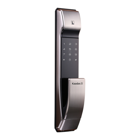
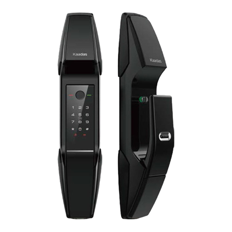
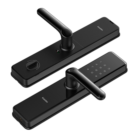
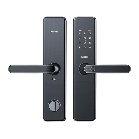
Kaadas S11-5W User manual

S110-5W
User Manual
www.kaadasgroup.com

Cautions
This section contains important information to ensure the user's safety and prevent potential damage to
property. Please, read this section carefully and use the product accordingly.
Content
1 How to install
Package Content
Explosive View
Before Installation
Installation Steps
2 Product Overview
Front Escutcheon
Back Escutcheon
3 How to set
Before set
Menu index
Access into master mode
Change master PIN code
Enroll user PIN code
Enroll fingerprint
Enroll card
Delete user PIN code
Delete fingerprint
Delete card
Opening Mode Setting
System Setting
System Query
Extension Function
4 How to use
Normal Mode
Open door by mechanical key override
Close door from outdoor/Close door from indoor/Double-lock from indoor
5 Other Features
Restore to Factory Setting
Reboot
Emergency Power Supply
Safe Handle Feature
Replace Battery

1 How to install
Package Content
This described package content is for reference only, the real products should be considered as final. If some
components lost, please check with the sellers.
Outside escutcheon
with rubber gasket
Inside escutcheon
with rubber gasket
Installation Template Mortise Strike Plate Assembly Mechanical Key
Mounting Plate RFID Card Screw pack User Manual Warranty card Micro-fiber Wiper
User manual
Screw pack
Warranty card

Explosive View
1. Back Cover
2. Connecting mounting screw(3pcs)
3. Inside escutcheon assembly
4. Pressure spring (2pcs)
5. Mounting plate
6. Mortise
7. Screw bolt (3pcs)
8. Outside escutcheon assembly
9. Square shaft (2pcs)
10. Fixed screw for key cylinder
11. Fixed screw (4pcs)
12. Key cylinder
13. Mechanical key cover
109 11 12 13
Please pressing the spring into the
end of the square shaft before
installing them
Caution:

Important Information
Safety instruction
•Read and understand all instructions before using this smart lock. Damages caused by failure to follow instructions is not
covered by the warranty.
•It is recommended to use the enclosures / accessories specified by the company.
•Use only alkaline batteries configured with this product.
•Do not forcibly disassemble this product in order to avoid alarm sound or damage to the product.
•Do not scratch the fingerprint reader with sharp objects, otherwise it may cause permanent damage.
•Do not expose the product to corrosive substances, so as not to damage the outer protective layer.
•Do not hand objects on the handle, so as not to affect the normal use of the door lock.
•When cleaning the product, please wipe it with a soft cloth.
•Do not disassemble the battery while the device is operating.
•Please choose a professional engineer to install the door lock and follow the company’s standard installation instruction,
and do not install it by yourself.
•After the door lock is installed, please modify the default master PIN code immediately and keep the mechanical key in
a safe place. Don’t disclosure PIN code to the unknown person.
•When low battery alarm is triggered, please replace all the batteries in time.
Warning
•Do not place battery closing to fire in case of explosion.
•Do not short-circuit the two poles of the battery lead with metal objects in case of explosion.
•Making sure replacement or maintenance are done by professional person authorized by Kaadas.
•Your warranty may invalidate if you used accessories produced by other manufacturer or not recommended by Kaadas.
Disposal of used battery and lock
•Please understand the local electronic product classification and collection system.
•Please follow the local regulations and do not discard used batteries into ordinary household garbage.
•Properly disposing of used products helps to avoid potential negative impacts on the environment and human health.

Before Installation
Check Door Open Direction
Right-out Right-in Left-out Left-in

Change latch bolt direction
1. Move the latch
both switcher to
the other end as
the arrow shows
2. Push the
latch bolt
inside the
mortise
3. Turn around
180 degree
4. Let the
latch bolt
eject
Make sure the position of directional screw is faced to the indoor direction, then fasten them properly.
Directional screw
Caution:

Change Handle Direction
Change Outside escutcheon Handle Direction
Screws
Positional
Component
Shield
Sleeve
Screws
Positional
Component
Shield
Sleeve
Taking out screws, positional
component and shield sleeve
in proper order.
Rotating the handle to the other
end.
Put the cable into the right end,
then place shield sleeve and
positional component on proper
order, and fasten the screws at
last.
Front panel
silicone pad
Front panel
silicone pad
Cable

Change Inside escutcheon Handle Direction
Taking out screws and positional
component in proper order.
Rotating the handle to the other
end.
Place positional component
and fasten the screws.
Default screw pack is for door thickness 38-60mm, please contact our dealer if other screw pack required.
Screws
Positional
Component
Shield
Sleeve
Screws
Positional
Component
Shield
Sleeve
Rear panel
silicone pad
Rear panel
silicone pad
Caution:

Installation Steps
1. Mark and drill bores by using the
installationtemplate first,then fix the
mortise into the doorframe and tighten
the screws to fix the mortiseon the door.
2. Put the key cylinder into the
corresponding position of the
mortise,then fasten it via tightening
the screw.
square shaft
Pressure spring
Connecting cable
for front panel
Do not make the mortise deadbolt come out.
3. Fix 3 screw bolts on the front panel,
place square shaft and pressure spring
into the bore.
Spring: the big end is downward.
Indoor
Connecting cable
for mortise
Connection screw bolts
Connection
screw bolts
Connection screw bolts
Caution: Caution:

4. Pass the connection wire through the bottom bore.
Then align and insert square into mortise to make the
front panel fit against the door closely.
5. Install the mounting plate with fixing
screws tightly against the door surface
to fix the front panel.
Connecting cable
for mortise
Mounting screw
Connecting cable
for mortise
Connecting cable
for front panel
Connecting cable
for front panel

6. Place pressure spring and square shaft in the back panel
in proper order. And insert the connecting cable of front
panel into related sockets of the back panel. Then align and
insert the square shaft and mechanical key pick into mortise
holes, make the back panel fit against the door closely. After
that, tighten the 2 screws.
7. Install the batteries and the battery cover. Then
install the striker assembly to finish the installation.
Please check handle, safe handle switch and
mechanical key if they are working properly.
According to the door thickness, cut the night latch key pick in
proper length.
1. After installing the striker assembly, please check if the
lock works smoothly by opening/closing door.
2. Test if mechanical key works smoothly after installation.
Connecting
mounting
screw
Connecting
mounting
screw
Square shaftSquare shaft
Pressure spring
Pressure spring
Connecting
cable
for mortise
Connecting
cable
for mortise
Connecting
cable
for front panel
Connecting
cable
for front panel
Caution: Caution:

2 Product Overview
Outside escutcheon Inside escutcheon
Touch keypad Back cover
Thumb turn
Safe handle switch
Card reader area
Fingerprint sensor
Emergency power USB port
Reset button
Pictures above are just for reference, please refer to the real product as final.
Caution:

3 How to set
Before set
There are normal mode and security mode in the product. The default mode is normal mode.
Security Mode Normal Mode
Master PIN code
User PIN code
Access to master mode Enter master PIN code Enter master PIN code
Fingerprint capacity
Card capacity
100
User number[00-99]
100
User number[00-99]
100
User number[00-99]
100
User number[00-99]
Yes
Default Master PIN code:12345678
6 groups
6-12 digits
[00-04] : Normal PIN code
[05-08] : One time PIN code(unavailable)
[09] : Duress Use
10 groups
6-12 digits
[00-04] : Normal PIN code
[05-08] : One time PIN code
[09] : Duress Use
Before setting to security mode, fingerprint, PIN code and Card, must be all enrolled or at least two different opening ways.
Yes
Default Master PIN code:12345678
Caution:

User Number
When you in security mode, you shall edit user number before enroll PIN code/fingerprint/card.
When you need to delete one user, you can enter the user number to delete.
You can fill your user information in below sheet for convenience
NO. Name PIN code Fingerprint Card

Menu index
1.There are voice prompts for the above operations, which can be operated according to the voice prompts
2.The user pin code and master pin code are 6-12 digits, and the default master pin code is 12345678.
Caution:
1. User setting
2. System setting
3. Record query
4. Functional extendsion
1. Add user pin code
2. Add user fingerprint
3. Add user card
4. Delete user pin code
5. Delete user fingerprint
6. Delete user card
7. Set the openning mode
9. Change master pin code
1. Volume setting
2. Language setting
1. System query
1. Join the network
2. Log off the network
Press【2】
Press【1】
Press【3】
Press【4】

Default master
PIN code is
12345678.
Access into master mode
Change master PIN code
1. Wake up touchscreen keypad with palm.
2. Press [*] twice, input master PIN code, and press [#]
to confirm.
3. Voice guide: Enter the Master Mode.
Note: Change default master PIN code is required
immediately for menu operation.
In master mode
Press 1 to user setting, then press 9 to change default
master PIN code.
Enter new master PIN code, press # to confirm. Reenter
the master PIN code, then press # to confirm. Voice
prompt of "Set up succeeded"
User Setting
Enroll user PIN code
Access into master mode
Enroll Fingerprint
Access into master mode
Enroll Card
Access into master mode
Press [1] for user setting.Then press [1] to enroll user
PIN code. Enter 2 digital user number (00-09), and
confirm with [#] key
Press [1] for user setting.Then press [2] to enroll user
fingerprint. Enter 2 digital user number (00-99), and
confirm with [#] key.
Place your finger on the fingerprint sensor, then take
away your finger after voice prompt "Remove finger
and scan again". Repeat above steps multiple times
until voice prompt "Enrollment succeed".
Enter user PIN code (6-12 digits), and confirm with [#]
key; Then repeat above operations .
Voice prompt of "Enrollment succeed"

Delete User PIN Code
Access into master mode
Delete User Fingerprint
Access into master mode
Delete User Card
Access into master mode
Opening Mode Setting
Access into master mode
Press [1] for user setting.Then press [3] to enroll user
card. Enter 2 digital user number (00-99), and confirm
with [#] key.
Press [1] for user setting.Then press [4] to delete user
PIN code. Press [1] to delete single user. Enter 2 digital
user number (00-09), and confirm with [#] key, Voice
prompt of "Deletion succeeded".
Press [1] for user setting.Then press [6] to delete user
card.Enter 2 digital user number (00-99), and confirm
with [#] key OR Place the related RF card on the card
icon area to delete until one beep sound.
Voice prompt of "Deletion succeeded"
Press [1] for user setting.Then press [7] for opening mode
setting.Press [1] for normal mode (single verification) ,which
means opening by PIN code or fingerprint or card.
Press [2] for security mode (double verification) ,which
means opening by PIN code+fingerprint or PIN code +card
or fingerprint+card.
Press [1] for user setting.Then press [5] to delete user
fingerprint. Press [1] to delete single user. Enter 2 digital
user number (00-99), and confirm with [#] key.OR Place
the related finger on the fingerprint sensor to delete until
one beep sound. Voice prompt of "Deletion succeeded"
Place card on the card icon area until beep sound and
voice prompt "Enrollment succeed".
Press [2] to delete all users
Voice prompt of "Deletion succeeded"
Press [2] to delete all users
Voice prompt of "Deletion succeeded"
Press [2] to delete all users.
Voice prompt of "Deletion succeeded"

OR
OR
OR OR OR OR
System Setting
Volume Setting
Access into master mode
Language Setting
System Query
Access into master mode
Extension Function
Access into master mode
Press [2] for system setting. Then press [1] for volume
setting.
Press [1] for voice mode.
Press [2] for mute mode, excluding alarm and menu
operation.
Press [4] for function extension.
Press [1] to join network.
Press [2] to log off network.
Press [2] for system setting.Then press [2] for language
setting.
Press [1] for Chinese Voice.
Press [2] for English Voice.
Press [3] for Spanish Voice.
Press [4] for Portuguese Voice.
Press [5] for Russian Voice.
Press [3] for system query.
Press [1] to get unique Serials Number.
System Query
Access into master mode

4 How to use
Open from outside
1. PIN code opening 2. Fingerprint opening 3. Card opening
Enter PIN code
Press the
handle to
open
Press the
handle to
open
Press the
handle to
open
Card reader area
Fingerprint sensor
Touch pad screen by palm to
lighten keypad ; Enter the
enrolled PIN code with end of [#].
Voice prompt “door opened” .
Press the handle to open the door.
Place the enrolled finger properly
on the fingerprint sensor area until
one beep sound and voice prompt
“door opened” Press the handle
to open the door.
Place the enrolled card properly on
the card icon area until one beep
sound and voice prompt
“door opened”. Press handle to open
the door.
Unlock by PIN code
Unlock by fingerprint
Unlock by card
In security mode, double verification is required for opening door.
1. PIN Code + Fingerprint
2. PIN Code + Card
3. Fingerprint + Card
Caution:
Table of contents
Other Kaadas Door Lock manuals
Popular Door Lock manuals by other brands

Abus
Abus wAppLoxx Pro Series Installation and operating instructions

Assa Abloy
Assa Abloy ESA500 Programming instructions

Longleaf Collection
Longleaf Collection PL/P-03C installation instructions

xpr
xpr HL1000-MF Installer manual

Dorex
Dorex 9500 Series installation instructions

Dato
Dato L-H300 user manual

LockNet
LockNet Sur-Lock I/O 2000L Series Appendix to the Installation Instructions

Salto
Salto WRDB0A4 K Series installation guide

Schlage
Schlage BE469 installation instructions

ACT
ACT ACTpro eLock User instruction manual

Allegion
Allegion Milre MI-5650 user manual

Kaba
Kaba SIMPLEX 3000 NARROW STILE installation instructions