Kallista P21650 User manual

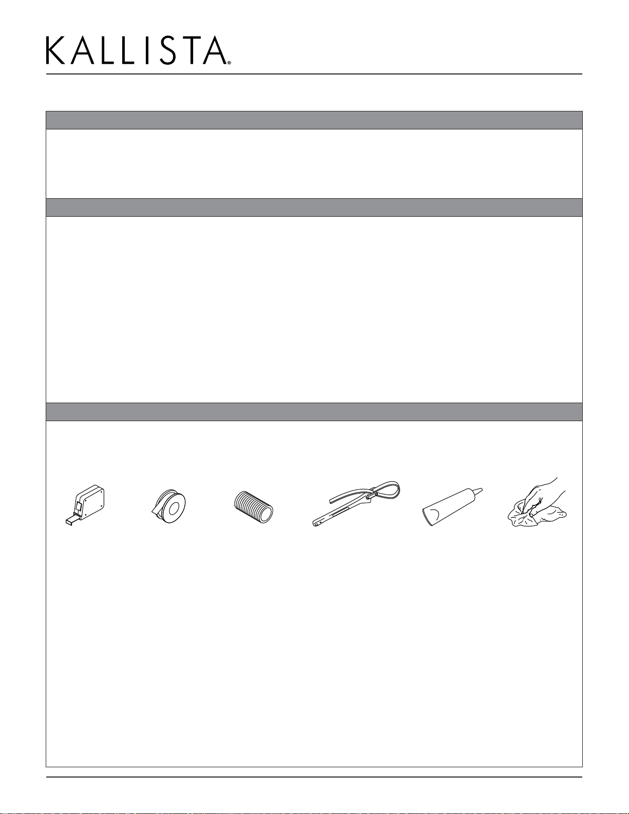
100% Silicone Sealant Sealant Tape Strap Wrench
Important Information
Follow all local plumbing and building
codes.
Shut off the water supply.
NOTICE: Choose an automatic
compensating valve with the appropriate
minimum flow rating, to assure your
valve will provide safety at the lowest
flow rates. For a showerhead with a
maximum flow rate of 1.75 gal/min (6.6
l/min), use with an automatic
compensating valve rated 1.5 gal/min
(5.7 l/min) or less.
IMPORTANT INSTRUCTIONS
Before using your shower, verify your
new showerhead is compatible with
your shower valve (located behind the
wall) by performing the following steps:
• While standing outside the shower,
turn on the shower valve. Do not step
into the shower.
• Adjust the water to your typical
showering temperature.
• Have someone flush the nearest toilet.
• With your hand, carefully check the
water temperature, from the
showerhead while the toilet is refilling.
• If the water becomes significantly
hotter, you will need to either replace
the shower valve with a compatible
KALLISTA valve or return your
showerhead.
CAUTION: Risk of scalding.
KALLISTA low-flow showerheads
are designed for use with compatible
KALLISTA valves. When installing a
low-flow product to an existing
showering system, verify compatibility
before showering. Do not use this
KALLISTA low-flow product with a
shower valve that allows the water
temperature to become too hot when
other plumbing products are used.
CAUTION: Risk of product
damage.
To avoid plugging the showerhead
spray outlets, use thread sealant tape
on the shower arm threads. Do not use
thread sealant compound (pipe dope).
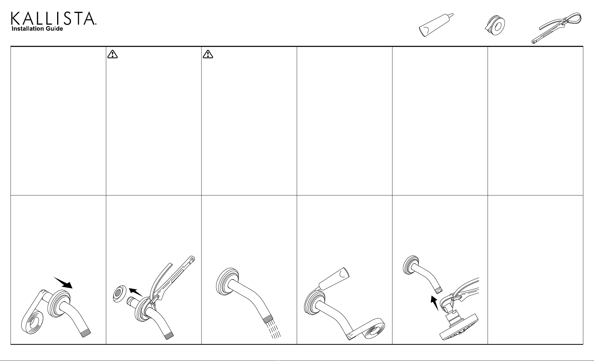
Record your model number.
5Use a clean strap wrench to secure
the showerhead to the arm.
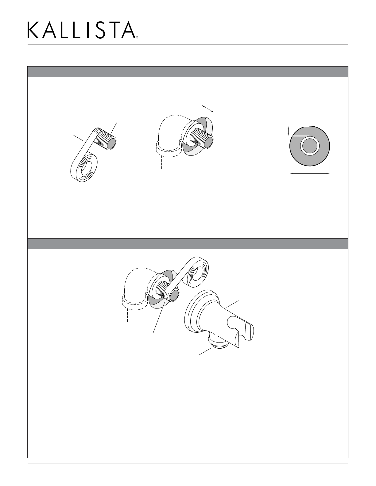
4Apply 100% silicone sealant around
the wall plate. Apply sealant tape to
the arm.
3Slide the plate against the wall. Run
water to flush debris.
2Install the arm. Tighten with a clean
strap wrench.
1Slide the wall plate onto the shower
arm. Apply sealant tape.
1333673-2-C

Questions? Problems? For additional assistance, please contact KALLISTA's
Customer Service Department at 1-888-4-KALLISTA (1-888-452-5547) or
kallista.com.
1333673-2-C© 2019 KALLISTA

INSTALLATION INSTRUCTIONS
Handshower, Hose
& HandshowerAccessories
1188577-2-FQuestions? Problems? For additional assistance, please contact KALLISTA’s Customer
Service Department at 1-888-4-KALLISTA (1-888-452-5547) or kallista.com
1 of 5
P21650, P21660, P24452, P24453,
P24454, P24456, P24743, P24745,
P24746, P24761, P24843
©2014 KALLISTA

INSTALLATION INSTRUCTIONS
Handshower, Hose
& HandshowerAccessories
1188577-2-E Questions? Problems? For additional assistance, please contact KALLISTA’s Customer
Service Department at 1-888-4-KALLISTA (1-888-452-5547) or kallista.com
2 of 5
THANK YOU FOR CHOOSING KALLISTA
We appreciate your commitment to KALLISTA quality products. Please take a moment to review this manual
before you install your KALLISTA product. If you encounter any installation or performance problems, please do
not hesitate to contact us at the phone number listed at the bottom of the page.
BEFORE YOU BEGIN
WARNING: Risk of scalding.High water temperature can cause severe burns. Set the water temperature
at or below 120°F (49°C) following the adjustment procedure in the valve Installation Instructions.
CAUTION: Risk of scalding. KALLISTAlow-flow showerheads/handshowers are designed for use with
compatible KALLISTAvalves. When installing a low-flow product to an existing showering system, verify
compatibility before showering. Do not use this KALLISTAlow-flow product with a shower valve that allows the
water temperature to become too hot when other plumbing products are used.
Prior to using your shower, verify your new showerhead/ handshower is compatible with your shower valve
(located behind the wall):
While standing outside the shower, turn on the shower valve. Do not step into the shower.
Adjust the water to your typical showering temperature.
Have someone flush the nearest toilet.
With your hand, carefully check the water temperature from the showerhead/handshower while the toilet is
refilling.
If the water becomes significantly more hot, you will need to replace the shower valve with a compatible
KALLISTAvalve or return your showerhead/handshower.
NOTE: Plumbing codes may require a vacuum breaker be installed in-line to handshowers. Please consult with
local plumbing codes.
Carefully plan the location of the wall supply elbow and fixed wall bracket to avoid the possibility of the
handshower hose interfering with the operation of any faucets and/or drains, etc.
Please read all instructions before you begin.
Observe all local plumbing and building codes.
Shut off the water supply.
Inspect the supply piping for damage. Replace as necessary.
KALLISTA reserves the right to make revisions in the design of products without notice, as specified in the
Price Book.

INSTALLATION INSTRUCTIONS
Handshower, Hose
& HandshowerAccessories
1188577-2-E Questions? Problems? For additional assistance, please contact KALLISTA’s Customer
Service Department at 1-888-4-KALLISTA (1-888-452-5547) or kallista.com
3 of 5
TOOLSAND MATERIALS
Adjustable WrenchDrill Pipe Wrench
Thread Sealant
Assorted Screwdrivers
Pencil Tape Measure Level Hex Wrench
.
1. INSTALL THE SUPPLY ELBOW (P24452)
O-Ring
Supply Elbow
Shower Ell
Apply thread sealant tape.
Adapter
Install a temporary nipple into the shower ell.
Run water through the system to flush out dirt and debris.
Remove the temporary nipple from the shower ell.
Apply several layers of sealant tape around the straight end of the threaded adapter.
Install the threaded adapter into the supply elbow.
NOTE: A hex wrench can be used to tighten the threaded adapter.
Apply several layers of sealant tape around the exposed tapered end of the threaded adapter.
Install the O-ring into the back of the supply elbow.
Thread the adapter and supply elbow onto the shower ell.
Turn on the water and allow water to flow through the supply elbow.
Check connection for leaks. Repair as needed.

INSTALLATION INSTRUCTIONS
Handshower, Hose
& HandshowerAccessories
1188577-2-E Questions? Problems? For additional assistance, please contact KALLISTA’s Customer
Service Department at 1-888-4-KALLISTA (1-888-452-5547) or kallista.com
4 of 5
2. INSTALL THE FIXED WALL BRACKET (P24453)
Screw
Press and hold
legs together.
Anchor
Fixed Wall Bracket
13/16"
(21 mm)
Drill holes using a 5/16" bit.
Determine the location for the fixed wall bracket.
Mark the hole locations for the wall anchors.
Drill the holes and install the wall anchors.
Attach the fixed wall bracket to the wall with the screws.
3. INSTALL THE HANDSHOWERAND HOSE
Handshower
Washer
Fixed Wall Bracket
Handshower Connector
Supply Elbow
Washer
Elbow Connector
Insert a washer into the elbow connector end of the shower hose.
Attach the shower hose to the supply elbow. Run cold and hot water through the shower hose to flush out
dirt and debris.
Insert the other washer into the threads of the handshower connector.
Thread the handshower into the shower hose. Tighten with an adjustable wrench.
Turn on the water. Check for leaks and smooth operation.
Place the handshower in the fixed wall bracket.

INSTALLATION INSTRUCTIONS
Handshower, Hose
& HandshowerAccessories
1188577-2-E Questions? Problems? For additional assistance, please contact KALLISTA’s Customer
Service Department at 1-888-4-KALLISTA (1-888-452-5547) or kallista.com
5 of 5
4. INSTALL THE OPTIONAL SLIDEBAR (P24456)
Cap
Setscrew
O-Ring
Coupling
Screw
Hub
Sleeve
Escutcheon
Anchor
Cap
Setscrew
O-Ring
Coupling
Tube
Handshower
Bracket
Drill a 5/16" hole
for the anchor.
Determine the location for the slidebar.
Mark the hole locations for the wall anchors.
Drill the holes and install the wall anchors.
Attach the escutcheons, sleeves, and hubs with the screws.
Slide the handshower bracket onto the tube.
Insert the couplings into the ends of the tube. Line up the holes in the tube with the holes in the couplings.
Place the tube over the sleeves.
Tighten the setscrews so they engage with the groove in the hubs.
Screw the caps onto the exposed ends of the setscrews.

INSTALLATION INSTRUCTIONS
Integrated Supply Elbow
1230883-2-B
1 of 3
Questions? Problems? For additional assistance, please contact KALLISTA’s Customer
Service Department at 1-888-4-KALLISTA (1-888-452-5547) or kallista.com.
Wall Bracket with
©2015 KALLISTA
P21652P21651

INSTALLATION INSTRUCTIONS
Integrated Supply Elbow
1230883-2-B
2 of 3
Questions? Problems? For additional assistance, please contact KALLISTA’s Customer
Service Department at 1-888-4-KALLISTA (1-888-452-5547) or kallista.com.
Wall Bracket with
THANK YOU FOR CHOOSING KALLISTA
We appreciate your commitment to KALLISTA quality products. Please take a moment to review this manual
before you install your KALLISTA product. If you encounter any installation or performance problems, please do
not hesitate to contact us at the phone number listed at the bottom of the page.
BEFORE YOU BEGIN
NOTE: Plumbing codes may require a vacuum breaker be installed in-line to handshowers. Please consult with
local plumbing codes.
Carefully plan the location of the wall bracket to avoid the possibility of the handshower hose interfering
with the operation of any faucets and/or drains, etc.
Please read all instructions before you begin.
Observe all local plumbing and building codes.
Shut off the water supply.
Inspect the supply piping for damage. Replace as necessary.
KALLISTA reserves the right to make revisions in the design of products without notice, as specified in the
Price Book.
TOOLSAND MATERIALS
1/2" NPT
Nipple
Sealant
Tape
Clear
Sealant
Strap
Wrench
Tape
Measure
Rags

INSTALLATION INSTRUCTIONS
Integrated Supply Elbow
1230883-2-B
3 of 3
Questions? Problems? For additional assistance, please contact KALLISTA’s Customer
Service Department at 1-888-4-KALLISTA (1-888-452-5547) or kallista.com.
Wall Bracket with
1. INSTALL THE PIPE NIPPLE
11/16" (17 mm) Beyond
Finished Wall
1/2" NPT
Nipple
Apply
sealant tape.
1-5/8" (41 mm) Max
3/8" (10 mm)
Max
Apply sealant tape to one end of a 1/2” NPT nipple.
Install the nipple to extend 11/16″(17 mm) beyond the finished wall.
Ensure the gap between the nipple and finished wall is no more than 3/8” (10 mm).
2. INSTALL THE WALL BRACKET
Outlet
Wall Bracket
Apply sealant tape.
Apply sealant tape to the exposed threads of the nipple.
Thread the wall bracket onto the nipple.
Using a clean strap wrench, tighten the bracket flush to the wall with the outlet oriented down.
Apply a bead of clear sealant around the perimeter of the bracket.
Turn on the water and allow water to flow through the bracket to flush out debris.
Check connection for leaks. Repair as needed.

INSTALLATION INSTRUCTIONS
Thermostatic Valve Trim
1048650-2-K
1 of 6 Questions? Problems? For additional assistance, please contact KALLISTA’s Customer
Service Department at 1-888-4-KALLISTA (1-888-452-5547) or kallista.com.
P23052-CR, P23052-LV, P23122-LV,
P23222-RK, P23222-LV, P24022-CL,
P24022-CR, P24022-KL, P24022-RB,
P24022-RL, P24122-CR, P24122-LV,
P24129-CR, P24129-LV, P24421-CR,
P24421-LV, P24422-CR, P24422-LV,
P24522-LV, P24522-TT, P24622-CR,
P24622-LV, P24722-LV
©2014KALLISTA

INSTALLATION INSTRUCTIONS
Thermostatic Valve Trim
1048650-2-K
2 of 6 Questions? Problems? For additional assistance, please contact KALLISTA’s Customer
Service Department at 1-888-4-KALLISTA (1-888-452-5547) or kallista.com.
THANK YOU FOR CHOOSING KALLISTA
We appreciate your commitment to KALLISTA quality products. Please take a moment to review this manual
before you install your KALLISTA product. If you encounter any installation or performance problems, please do
not hesitate to contact us at the phone number listed at the bottom of the page.
BEFORE YOU BEGIN
Please read all instructions before you begin.
Prior to installation, unpack the valve trim and inspect it for damage. Return it to the carton until installation.
Observe all local plumbing and building codes.
Shut off the water supply.
The appearance of your product may differ from what is shown in these instructions, however, the
installation procedure is the same.
KALLISTA reserves the right to make revisions in the design of products without notice, as specified in the
Price Book.
TOOLSAND MATERIALS
Assorted
Screwdrivers
Assorted
Hex Wrenches
Adjustable
Wrench

INSTALLATION INSTRUCTIONS
Thermostatic Valve Trim
1048650-2-K
3 of 6 Questions? Problems? For additional assistance, please contact KALLISTA’s Customer
Service Department at 1-888-4-KALLISTA (1-888-452-5547) or kallista.com.
1. INSTALL THE VALVE STEM ADAPTER
Spline Adapter
Select the correct valve
stem adapter and screw.
Valve Stem Adapter
NOTE: Check the finished wall surface as related to the graphics on the plaster guard.
Select the correct length valve stem adapter and screw for your application. Refer to the information
stamped on the plaster guard to verify the wall thickness.
Thin wall - 3/16” (5 mm) to 9/16” (14 mm): Use the 7/8” (22 mm) (short) valve stem adapter, stamped “3”
on the plaster guard, and the 1-3/8” (35 mm) screw.
Standard wall - 9/16” (14 mm) to 1-1/16” (27 mm): Use the 1-3/8” (35 mm) (medium) valve stem adapter,
stamped “1” on the plaster guard, and the 1-3/4” (44 mm) screw.
Thick wall - 1-1/16” (27 mm) to 1-9/16” (40 mm): Use the 1-7/8” (48 mm) (long) valve stem adapter,
stamped “2” on the plaster guard, and the 2-3/8” (60 mm) screw.
Remove and discard the plaster guard from the valve.
Place the spline adapter over the valve stem.
Set the valve stem adapter over the spline adapter. Do not completely press or screw the valve stem
adapter into place until instructed to do so.

INSTALLATION INSTRUCTIONS
Thermostatic Valve Trim
1048650-2-K
4 of 6 Questions? Problems? For additional assistance, please contact KALLISTA’s Customer
Service Department at 1-888-4-KALLISTA (1-888-452-5547) or kallista.com.
2. ADJUST THE HANDLEASSEMBLY
Valve Stem Adapter
Spline Adapter
Handle Assembly
Ensure the valve stem adapter is lightly placed over the spline adapter.
Place the handle assembly over the valve stem adapter.
Turn the handle clockwise until the stop is contacted. The valve will be in the full cold position. The handle
should be between 9 and 10 o’clock positions. To adjust the position of the handle, refer to the alignment
instructions below.
Rotate the handle assembly counterclockwise, through the detent, then to the high temperature limit stop.
Verify that the handle assembly is between the 3 and 4 o’clock position.
Rotate back to the 6 o’clock position.
Remove the handle assembly and set aside.
HandleAlignment Adjustments
NOTE: The spline adapter allows fine adjustment of the handle alignment.
Remove the handle assembly and the valve stem adapter.
Reposition the spline adapter.
Reinstall the handle assembly and the valve stem adapter.
Check the alignment.
Repeat until the handle alignment is satisfactory.

INSTALLATION INSTRUCTIONS
Thermostatic Valve Trim
1048650-2-K
5 of 6 Questions? Problems? For additional assistance, please contact KALLISTA’s Customer
Service Department at 1-888-4-KALLISTA (1-888-452-5547) or kallista.com.
3. INSTALL THE FRONT PLATE
Valve Stem
Adapter
7/16"
(11 mm)
MAX
Verify the seal covers the wall opening.
Nut
Screw
Stud
Ensure the valve stem adapter is firmly pressed onto the valve stem.
Secure the valve stem adapter to the valve with the correct length screw, as selected in the “Install the
Valve StemAdapter” section of this guide.
Thread the two studs into the threaded holes of the valve.
Place the front plate assembly over the studs.
Thread the nuts onto the studs to secure the front plate assembly to the wall. Do not overtighten the nuts.
NOTE: If the front plate assembly does not lay flat on the wall surface, loosen the nuts and adjust the threaded
studs, then retighten the nuts. Once properly installed, the threaded studs must not protrude more than 7/16”
(11 mm) through the front plate assembly.
Visually inspect the front plate assembly to ensure the foam seal is completely covering the wall opening. If
not, stop the installation and repair the wall opening.

INSTALLATION INSTRUCTIONS
Thermostatic Valve Trim
1048650-2-K
6 of 6 Questions? Problems? For additional assistance, please contact KALLISTA’s Customer
Service Department at 1-888-4-KALLISTA (1-888-452-5547) or kallista.com.
4. INSTALL THE TRIM
Escutcheon
Escutcheon Adapter
Ring
P24722-LV TrimAll other Trim
Setscrew
Front of Adapter Ring
NOTE: If installing the P24722-LV trim, proceed to the “For P24722-LV” section below.
Place the escutcheon on the wall with the drain notch located downward in the 6 o’clock position.
Thread the handle assembly onto the hub of the front plate assembly to secure the escutcheon in place.A
lever handle should point downward in the 6 o’clock position.
NOTE: If the handle does not engage the valve or the escutcheon does not tighten to the wall, replace the
valve stem adapter with an adapter of appropriate length.
For P24722-LV
Thread the adapter ring onto the hub of the front plate assembly.
Place the escutcheon on the wall with the drain notch located downward in the 6 o’clock position.
Place the handle assembly against the escutcheon by lining up the pins in the handle assembly with the
holes in the escutcheon. Make sure the handle is pointing down to the 6 o’clock position and the setscrew
hole is facing down.
Verify the setscrew will contact the front angle of the adapter ring. Thread the adapter ring in or out until
appropriate setscrew contact is achieved.
Tighten the setscrew with a hex wrench. Make sure the handle assembly is tight against the escutcheon.

Installation Guide
Thermostatic Mixing Valves
Français, page “Français-1”
Español, página “Español-1”
P29511, P29512
1170591-2-A

IMPORTANT INSTRUCTIONS
READ AND SAVE FOR THE
CONSUMER
WARNING: Risk of scalding or other severe injury.
CAUTION: Risk of scalding hazard. This device has been
calibrated at the factory to ensure a safe maximum water
temperature. Any variance in settings or water inlet
conditions from those used during factory calibration may
raise the discharge temperature above the safe limit, and may
present a scalding hazard.
•Before completing installation, the installer must set the
maximum water temperature setting of this valve to minimize the
risks associated with scalding hazards according to ASTM F 444.
The installer is responsible for adjusting the maximum water
temperature of this valve according to instructions.
This valve meets or exceeds ANSI A112.18.1 and ASSE 1016.
If you do not understand any of the temperature adjustment
instructions in this document, in the United States please contact our
Customer Care Center at 1-888-4-KALLISTA. Outside the U.S., please
contact your distributor.
IMPORTANT NOTICE: Please fill in the blanks on the valve label.
Retain this guide for future reference.
•The valve is calibrated to 104°F (40°C) at the first stop position,
and the maximum temperature limit stop is positioned so the
outlet water temperature does not exceed 120°F (49°C).
•Factory calibrated inlet conditions are:
Hot and cold water pressure = 43-1/2 psi (300 kPa)
Hot water supply temperature = 149°F (65°C)
Cold water supply temperature = 59°F (15°C)
•If inlet conditions differ from those used during factory
calibration, it may be necessary to re-calibrate the valve after
installation. The installer must check the mixed flow
temperature after installation, and adjust the valve as needed
according to the instructions.
1170591-2-A 2 Kallista

Tools
Before You Begin
WARNING: Risk of scalding or other severe injury. Before
completing installation, the installer must set the maximum
water temperature setting of this valve to minimize the risks
associated with scalding hazards according to ASTM F 444.
CAUTION: Risk of personal injury. If the water temperature
is set too high, scalding will occur. The water temperature
should never be set above 120°F (49°C).
CAUTION: Risk of scalding. This device has been calibrated
at the factory to ensure a safe maximum water temperature.
Any variance in settings or water inlet conditions from those
used during factory calibration may raise the discharge
temperature above the safe limit, and may present a scalding
hazard. Responsibility for installation and adjustment of this
device in accordance with these instructions lies with the
installer.
NOTICE: Risk of product damage. This valve contains plastic and
rubber components. Do not sweat or braze directly to the valve
body. Do not apply excessive heat to the valve body when you
make solder connections. Do not apply flux or acids directly to the
valve, as damage to the seals, plastic components, and trim finish
may result.
Thermometer
Solder
Hacksaw or
Tubing Cutter
10 mm
Hex Wrench
Propane
Torch
Adjustable
Wrench
Thread
Sealant
Assorted
Screwdrivers
Strap Wrench
Wrench and
1/2" (13 mm)
Hex Socket
Pipe
Wrench
Kallista 3 1170591-2-A

Before You Begin (cont.)
NOTICE: Risk of product damage. Do not apply petroleum-based
lubricants to the valve components, as damage may result.
NOTICE: Risk of product damage. Inlet and outlet threaded joint
connections should be made with plumbers PTFE tape or liquid
sealant. Oil-based, non-setting compounds should not be used.
NOTICE: Do not force the handle in any direction. Forcing the
handle will damage the valve.
Observe all local plumbing and building codes.
Shut off the main water supply.
Inspect the supply piping for damage. Replace as necessary.
The bottom port of the thermostatic mixing valve is intended for
use as a bath filler only. If a bath spout is not used with this
product, cap the bottom port.
The P29511 and P29512 thermostatic mixing valves do not contain
an integral volume control/shut-off valve. You must install a
separate volume control/shut-off valve (P29527 or P29528)
downstream of any used valve outlet.
The thermostatic mixing valves do not have an integral aspirator.
For installations that use a bath diverter spout, you must install a
twin ell with integral aspirator between the valve and the bath
spout. If these thermostatic mixing valves are installed without an
aspirator, it will cause water to flow from the shower and bath
spout at the same time.
Determine the correct drain size and capacity for your
installation. If two thermostatic mixing valves are used together,
water volumes between 18 and 30 gpm (60 and 114 lpm) or more
are possible, depending upon the water supply pressure.
Determine the correct water heater size and capacity for your
installation. A typical shower installation uses an approximate
mix of 75% hot water and 25% cold. A custom shower application
using three 2-1/2 gpm (9.5 lpm) showerheads can use about 45
gallons (170 liters) of hot water in 8 minutes. Choose a water
heater large enough for your installation.
The valve is calibrated to 104°F (40°C) at the first stop position.
The maximum temperature limit stop is positioned so the outlet
water temperature does not exceed 120°F (49°C).
1170591-2-A 4 Kallista
Other manuals for P21650
1
This manual suits for next models
10
Table of contents
Languages:
Other Kallista Bathroom Fixture manuals

Kallista
Kallista P21500 User manual

Kallista
Kallista P22731 User manual

Kallista
Kallista Tuxedo P72037 User manual

Kallista
Kallista P50018 User manual

Kallista
Kallista P24760 User manual

Kallista
Kallista PERFECT P74235-WO-0 User manual

Kallista
Kallista P21500 User manual

Kallista
Kallista P50206 User manual

Kallista
Kallista P21520 User manual

Kallista
Kallista CENTRAL PARK WEST P21386-00-SN User manual