KAM iLINK GREEN User manual

iLINK GREEN
Linkable green DMX laser with remote control
Green DMX laser with remote control
Part of the Kam iLink laser series
Stepping motor
Full remote control
Full DMX512 operation
8 DMX channels
Auto mode / Sound-to-Light via built-in mic
Master/Slave modes
LED display
Tough metal chassis / Adjustable metal hanging bracket / Safety chain loop
Safety key On/Off lock
Mains fused IEC
MANUAL VERSION 1.0
28-06-12
For the latest instruction manual updates and information on the entire Kam range visit:
www.kam.co.uk
Kam products are manufactured by: Lamba plc, Unit 1, Southfields Road, Dunstable, Bedfordshire, United Kingdom LU6 3EJ
Telephone: (+44) (0)1582 690600 • Fax: (+44) (0)1582 690400 • Email: [email protected] • Web: www.lambaplc.com
If this product is ever no longer functional please take it to a recycling plant for environmentally friendly disposal.
Due to continuous product development, specifications and appearance are subject to change.
© Copyright Lamba plc 2012. E&OE.

Thank you for purchasing this KAM product, we are sure that it will serve you for many years to come.
To optimise the performance of this product, please read these operating instructions carefully to familiarise yourself
with the basic operations of this unit. After you have read the instructions, please retain them for future reference.
This unit has been tested at the factory before being shipped to you.
To prevent or reduce the risk of electrical shock or fire, do not expose the unit to rain or moisture. To prevent a fire
hazard, do not expose the unit to any naked flame sources. Unplug this apparatus during lightning storms or if it is
unlikely to be used for long periods of time.
When installing the unit, please ensure you leave enough space around the unit for ventilation. Slots and openings in
the unit are provided for ventilation to ensure reliable operation of the product and to protect it from overheating. To
prevent fire hazard, the openings should never be blocked or covered.
Always handle the power cable by the plug. Never pull out the plug by pulling on the cable. Never touch the power
cable when your hands are wet as this could cause an electric shock. Do not tie a knot in the cable. The power cable
should be placed such that it is not likely to be stepped on. A damaged power cable can cause a fire or give you an
electrical shock. Check
the power cord periodicaly, if you ever find that it is damaged, replace it before using the unit again. Contact your
retailer for a replacement.
The voltage of the available power supply differs according to country or region. Be sure that the power supply
voltage of the area where this unit is to be used meets the required written on the unit.
The lightning flash symbol inside a triangle is intended to alert the user to the presence high voltage within
the unit’s enclosure that may be of sufficient power to constitute a risk of electrical shock to persons.
Caution: to prevent the risk of electric shock, do not attempt to open the unit. No user-serviceable parts
inside. Refer all servicing to qualified service personnel.
The exclamation mark inside a triangle is intended to alert the user to the presence of important operating
and maintenance instructions in the literature accompanying the appliance.
Any modification carried out on the unit may invalidate the unit’s warranty.
If applicable, only use the stand, tripod or bracket specified or sold with the apparatus.
Select the installation location of your unit carefully. Avoid placing it in direct sunlight or locations subject to vibration
and excessive dust. Do not use the unit where there are extremes in temperature (below 41ºF / 5ºC or exceeding
95ºF / 35ºC).
Unpacking and safety: Please unpack your new product carefully, your new product should reach you in perfect
condition. Please check that no damage has occurred during transit. If any damage is found, do not operate your unit.
Please contact the retailer you purchased it from immediately. If there is any damage to the mains cable do not use
the device. Always disconnect the unit from the mains supply when carrying out any servicing or cleaning of the unit.
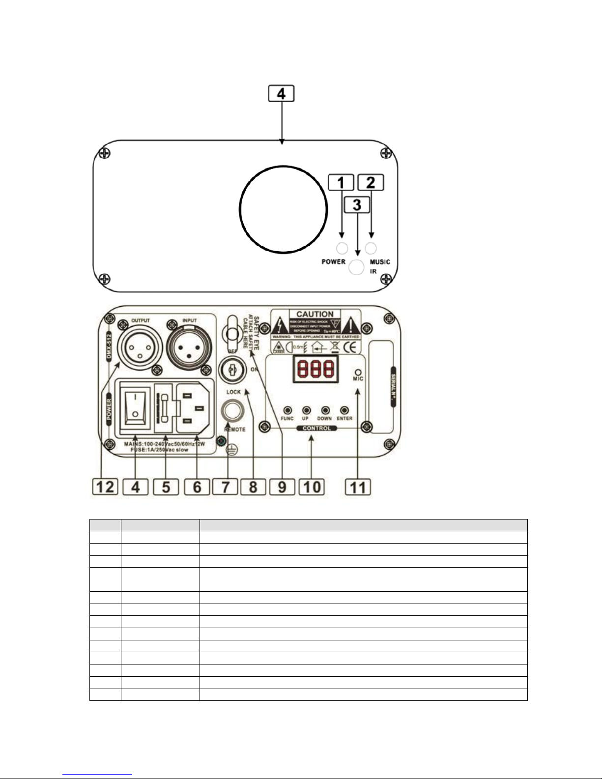
The serial number for this equipment should be located on the rear or underside of the unit. Please make a note of
this number as you will need it for your warranty, it is a good idea to keep a copy of the serial number for your own
records.

Panel
NO.
NAME
DESCRIPTION
1
Power LED
Indicates the laser is switched on
2
Music LED
Sound-to-Light signal
3
IR Receiver
Remote controller signal receiver
4
Laser Aperture
The laser effect output aperture. NEVER LOOK INSIDE THE FIXTURE THROUGH
THIS APERTURE WHILE FIXTURE IS OPERATING.
4
Power Switch
Switch ON and OFF the fixture
5
Fuse Holder
Replace fuse with correct value if required
6
Main Power Input
IEC socket and integrated fuse holder.
7
Interlock
For laser emergency stop
8
Key switch
Safety key switch operates laser output
9
Safety eye
Attach the safety cable/chain
10
Control panel
LED menu function display
11
Microphone
To detect the music/sound signal
12
DMX Input/Output
3 pins male/female XLR connector

Control & Function
Regular breaks during operation are essential to maximize the life of this device as it is not designed for continual
use. Always unplug the unit when it is not being used for long periods or before servicing. In the event of serious
operation problems, stop using the unit and contact your dealer immediately.
Note:There will output from laser 5 seconds after the unit is powered on.
Operation
Standalone pre-program laser show
Press FUNC to enter MODE OPTION.
Till the LED panel shows AUt.
Press ENTER to confirm the setting.
Auto mode
The laser will return to Auto mode once the power is turned off/on.
Sound activated show (Music Show) Standalone mode
Press FUNC to enter MODE OPTION.
Till the LED panel shows SoU.
Press ENTER to confirm and save the setting.

Sound activated mode sensitivity setting
Press FUNC till to see S **.
Press UP/DOWN to set microphone sensitivity. S 0 is no sound activation, from S1 to S9 is sound activated, S1 min S9 max.
Press ENTER to confirm and save the setting.
The sound sensitivity can be adjusted to determine how sensitive the laser is to sound. In the S** mode there are 10 different
options.
Zero = sound off
1-9 = from low to high sensitivity
A suggested setting would be in the range of 5-7. If this range is too sensitive reduce the value, if more sensitivity is required
increase the value. Remember to press enter to confirm your selection.
This setting will remain in the memory when powered off (and permanently stored in the flash memory).
DMX mode
Press FUNC to enter MODE OPTION.
Till to LED panel shows 001.
Use the up / down buttons to select the desired DMX starting address
Press ENTER to confirm the setting.
The laser is working in “DMX MODE”. With the help of UP/DOWN button, choose your DMX starting address.
Master/slave mode
Linking several units without a DMX controller
Master unit
Press FUNC and select desired auto option sound or auto
Press the enter button to confirm
Slave unit
Press the mode button until LED panel shows SLA
Press ENTER to confirm the setting.
All units set to SLA will follow the master unit
These must be linked together using a 3pin XLR DMX cable (not supplied)
Note: only one unit must be set to master all other units set to slave.
When linking this unit to other iLink lasers always use the iLink Green as the master unit and the other units as slave
units, this will allow the remote to control all the lasers.

Remote mode
Press FUNC to enter MODE OPTION.
Until the LED panel shows REN
Press ENTER to confirm the setting.
Remote instructions
Button
Function
Description
ON/OFF
In REM mode, to turn ON/OFF laser. In any stand alone
mode, except for SLA mode, pressing this button for 2
seconds will activate the REM mode.
Auto
Auto running slow
Music
Sound Activated show. The blue music LED indicator is
flashing when sound signal is detected.
Sound
sensitivity
In Sound Activated Mode, press Music + B + “1-9” to adjust
the sensitivity setting. “9” is the most sensitive.
N/A
No function
Pattern
changing
To show and change patterns
Fixed pattern
Choose favourite pattern from 1 to 48
Pattern repeat
Last pattern and current pattern cycle repeating

Controlling units via DMX - each unit uses 8 DMX channels
To set the DMX address
1. Press the function button until *** is displayed (range 001-512)
2. Using the up / down buttons select the desired DMX staring address
3. Press the enter button to confirm
4. Continue this formula to address any additional units
Note on setting the DMX address of units - if one or several units are to be controlled at the same time with the same
features set, all units DMX address needs to be the same
Example all units to 001
If individual control of several units is required
Each unit must have its on unique address and no channels must cross
Example unit 1 set to 001 – unit 2 to 09 etc adding 8 clear channels each time
Master slaving units with no DMX controller
Set the master unit to the desired setting
Example auto or sound
Set all other units to slave mode
To set slave mode press the function button until SLA is displayed then press the enter button to confirm
Only one unit must be set as a master and all other units as a slave
Connect each unit together via a 3pin DMX lead
DMX Protocol
CHANNEL
VALUE
FUNCTION
CH1 MODE
000-063
Laser black out
064-127
Auto show
128-191
Sound activated show (music)
192-255
DMX MODE (other channels activated)
CH2 PATTERN
000-255
32 Patterns as shown in PATTERN LIST
CH3 ZOOMING
000-127
100%-5% Size
128-169
Zooming in
170-209
Zooming out
210-255
Zooming in and out
CH4 Y AXIS ROLLING
000-127
0 -359 degree fixed Y axis rolled
128-191
Clockwise rolling
192-255
Anticlockwise rolling
CH5 X AXIS ROLLING
000-127
0 -359 degree fixed X axis rolled
128-191
Clockwise rolling
192-255
Anticlockwise rolling
CH6 Z AXIS ROLLING
000-127
0 -359 degree fixed Z axis rotate
128-191
Clockwise rotating
128-255
Anticlockwise rotating
CH7 X AXIS MOVING
000-127
128 different fixed position on X
128-191
Clockwise moving
128-255
Anticlockwise moving
CH8 Y AXIS MOVING
000-127
128 different fixed position on Y
128-191
Clockwise moving
128-255
Anticlockwise moving

Pattern list in channel 2
DMX
PATTERNS
DMX
PATTERNS
DMX
PATTERNS
DMX
PATTERNS
000-007
064-071
128-135
192-199
008-015
072-079
136-143
200-207
016-023
080-087
144-151
208-215
024-031
088-095
152-159
216-223
032-039
096-103
160-167
224-231
040-047
104-111
168-175
232-239
048-055
112-119
176-183
240-247
056-063
120-127
184-191
248-255
Specifications
Mains Input
AC100-240V, 50/60Hz
Fuse
250V 1 A slow blow (20mm Glass)
Total Power
12W
Music Control
Internal microphone
Laser Power
40mW 532nm green laser
Laser Classification
Class 3B
Laser Safety Standard
EN60825-1 2007
Condition Temperature
10~40ºC
DMX Connections
3 pins XLR Male/Female
DMX Channels
8 channels
Measurement
145 x 160 x 80mm
N Weight
1.3 Kg
Table of contents
Other KAM Lighting Equipment manuals

KAM
KAM LED Barrel 1 User manual

KAM
KAM Laserscan 300 3D User manual

KAM
KAM LED Scanner 1 User manual

KAM
KAM Partybar Eco User manual

KAM
KAM iLink RGB Pro User manual

KAM
KAM LED Moonlite 15 User manual

KAM
KAM PowerStrip5 User manual

KAM
KAM DMX Laser Tri 160 FScan User manual

KAM
KAM LED Disco Dome DMX User manual

KAM
KAM Star Cluster Micro RB 300 User manual

KAM
KAM LED PARBAR MKIII User manual

KAM
KAM K-UV 18X1W Strip User manual

KAM
KAM DMX LASER 120 PRO User manual

KAM
KAM Kam iLink RGY User manual

KAM
KAM DMX STAR CLUSTER User manual

KAM
KAM Laser Tri260 SD FScan User manual

KAM
KAM Derby 8 User manual

KAM
KAM KML412 User manual

KAM
KAM LED Rodeo User manual

KAM
KAM KML407 User manual