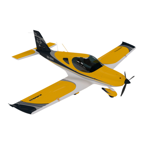
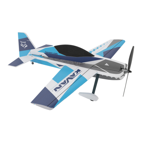
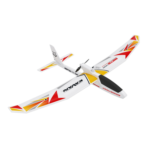
Kavan BETA 1400 Kit User manual

BETA 1400
Instruction Manual / Návod ke stavbě/Bauanleitung / Návod na stavbu
PRECAUTIONS:
This R/C model is not a toy. Use it with care and stricktly following the instructions in this
manual.
Assemble this model following stricktly these instructions. DO NOT modify or alter the mod-
el. Failure to do so, the warranty will lapse automatically. Follow the instructions in order to
obtain a safe and solid model at the end of the assembly.
Children under the age of 14 must operate the model under the supervision of an adult.
Assure that the model is in perfect conditions before every ight, taking care that all the
equipment works correctly and that the model is undamaged in its structure.
Fly only in days with light breeze and in a safe place away from any obstacles.
UPOZORNĚNÍ:
Tento RC model není hračka. Je určen k provozování osobami staršími 15 let.
Model dokončete a připravte k letu PŘESNĚ podle návodu. Model NEUPRAVUJTE, v opačném
případě automaticky ztrácí záruka svoji platnost.
Model provozujte opatrně a ohleduplně, důsledně se řiďte pokyny v tomto návodu.
Před každým letem se ujistěte, že model je v prvotřídním stavu, dbejte, aby všechny části
pracovaly správně, a model nebyl poškozený.
S modelem létejte na vhodné ploše bez překážek, stromů, elektrických vedení apod. Vyhle-
dejte bezpečné místo, mimo cesty a veřejné komunikace, dbejte na bezpečnost přihlížejících
diváků.
VORSICHTSMAßNAHMEN:
Dieses R/C Modell ist kein Spielzeug. Benutzen Sie es mit Vorsicht und halten
Sie sich an die Anweisungen in dieser Anleitung. Bauen Sie das Modell gemäß der Anleitung
zusammen. Modizieren und verändern Sie das Modell nicht. Bei Nichteinhaltung erlischt die
Garantie. Folgen Sie der Anleitung um ein sicheres und haltbares Modell nach dem Zusam-
menbau zu erhalten.
Kinder unter 14 Jahren müssen das Modell unter Aufsicht eines Erwachsenen betreiben.
Versichern Sie sich vor jedem Flug, dass das Modell in einwandfreiem Zustand ist, dass alles
einwandfrei funktioniert und das Modell unbeschädigt ist.
Fliegen Sie nur an Tagen mit leichtem Wind und an einem sicheren Platz ohne Hindernisse.
UPOZORNENIE:
Tento RC model nie je hračka. Je určený na prevádzkovanie osobami staršími ako 14 rokov.
Model dokončite a pripravte k letu PRESNE podľa návodu. Model neupravujte, v opačnom
prípade automaticky stráca záruka svoju platnosť.
Model prevádzkujte opatrne a ohľaduplne, dôsledne sa riaďte pokynmi v tomto návode.
Pred každým letom sa uistite, že model je v prvotriednom stave, dbajte, aby všetky časti pra-
covali správne, a model nebol poškodený.
S modelom lietajte na vhodnej ploche bez prekážok, stromov, elektrických vedení apod.
Vyhľadajte bezpečné miesto, mimo cesty a verejné komunikácie, dbajte na bezpečnosť pri-
zerajúcich
Kit
Kit


BETA 1400 Kit
Instruction Manual
Congratulation on your purchase of the BETA 1400 motor powered glider. You
are about to embark on a magical journey into the fascinating world of electric
powered RC aeroplanes.
The BETA 1400 manufactured of the virtually unbreakable EPO foam packed
with the latest 2.4GHz radio technology and powered with a mighty brushless
motor and Li-Po batteries will help to become an experienced pilot in no time!
BETA 1400 is not just an entry level plane but actually a quite good thermal glider
that will please any Sunday pilot - a newcomer as well as a seasoned pro!
Wingspan 1400 mm
Length 966 mm
All-up Weight 700-770 g
Wing Area 24.5 dm2
Wing Loading 28.6-31.4 g/dm2
Recommended Motor* C2814-1400 outrunner
Recommended ESC* KAVAN R-20B 20 A with BEC 5 V
*) Not supplied in the kit.
• EPO foam moulded parts, small accessories, 7x6” folding prop and spinner,
2 sheets of stickers
General Warnings
An R/C aeroplane is not a toy! If misused, it can cause serious bodily harm and
damage to property. Fly only on a safe place following all instructions and
recommendations in this manual. Beware of the propeller! Keep loose items
that can get entangled in the propeller away from the spinning propeller,
including loose clothing, or other objects such as pencils and screwdrivers.
Ensure that yours and other people’s hands, and face are kept away from the
rotating propeller.
Note on Lithium Polymer Batteries
Lithium Polymer batteries are signicantly more vulnerable than alkaline or
NiCd/NiMH batteries used in R/C applications. All manufacturer’s instruc-
tions and warnings must be followed closely. Mishandling of LiPo batteries
can result in re. Always follow the manufacturer’s instructions when dispos-
ing of Lithium Polymer batteries.
Additional Safety Precautions and Warnings
As the user of this product, you are solely responsible for operating it in a
manner that does not endanger yourself and others or result in damage to
the product or the property of others. This model is controlled by a radio
signal that is subject to interference from many sources outside your control.
This interference can cause momentary loss of control so it is advisable to al-
ways keep a safe distance in all directions around your model, as this margin
will help to avoid collisions or injury.
Never operate your model with low transmitter batteries.
Always operate your model in an open area away from power lines, cars, traf-
c, or people.
Avoid operating your model in populated areas where injury or damage can
occur.
Carefully follow the directions and warnings for this and any optional sup-
port equipment (chargers, rechargeable batteries, etc.) which you use.
Keep all chemicals, small parts and anything electrical out of the reach of
children.
Moisture causes damage to electronics. Avoid water exposure to all equip-
ment not specically designed and protected for this purpose.
Never lick or place any portion of your model in your mouth as it could cause
serious injury or even death.
SAFETY PRECAUTIONS
INTRODUCTION
• Builder’s kit, EPO foam parts
• Aileron, elevator, rudder and throttle control
• Easy handling and high stability; durable, virtually unbreakable electric
motor powered glider
• Powerful brushless outrunner motor (not supplied in the kit)
• Large wing area, low weight
• Lightweight Li-Po ight pack (not supplied in the kit)
FEATURES
SPECIFICATION
KIT CONTENTS
YOU WILL ALSO NEED THE FOLLOWING ACCESSORIES AND TOOLS (not included in the kit)
RC Set, Power Unit, Battery
At least a 4-channel transmitter and receiver, Li-Po ight pack 11.1 V 1600-
2700 mAh, KAVAN C2814-1400 brushless motor or similar, KAVAN R-20B 20
A ESC or similar, 4x KAVAN GO-09 servos or similar, short Y-cable or 2x 20-30
cm extension cable.
Tools:
Small Phillips and at screwdrivers, 1.5 mm Allen key or screwdriver, hot melt
glue gun, sandpaper No. 150-200.
Glue:
Medium or thick cyanoacrylate glue (e.g. KAV9952 or KAV9953), low or medi-
um strength threadlocker (blue - e.g. KAV9970), hot melt glue or MS polymer
glue (e.g. BISON Poly Max®, Soudal T-Rex®), clear sticky tape.
1

2
The fuselage is supplied unassembled (with pre-installed push rods, carbon
and plywood reinforcements) in the Kit - you are supposed to install the
servos, motor and glue the fuselage halves together.
Roughen the contact areas with No. 150-200 sandpaper before applying
glue.
1. Rudder Servo Installation (Fig. 1)
• Locate the right fuselage half. You will nd the KAVAN GO-09-sized bay for
the rudder servo in the rear part of the cockpit compartment.
• Prepare the one side arm supplied with the KAVAN GO-09 (or cut a two-
side arm to one side arm). Turn on your transmitter, set the rudder stick and
trim to the centre (neutral). Connect the rudder servo to the appropriate
receiver output (CH4 with the T8FB), plug the ESC’s cable to the throttle
channel (CH3 with the T8FB) and connect the ight pack. Insert the Z-bend
on the end of the elevator push rod into the middle hole in the servo arm
(ca 10 mm from the centre of the arm). Now insert the servo into the servo
bay so the servo output shaft was closer to the nose.
• Now attach the servo arm on the output shaft of the servo - it should be
square to the side of the servo case as much as possible. Secure the servo
arm with the screw supplied with the servo. Glue the servo with drops of
hot melt glue or MS polymer glue over the servo lugs. You can use a me-
dium CA as well, but the hot melt glue or MS polymer glue could be eas-
ily removed without damage to your model if you ever needed to get the
servo out.
2. Motor Mount (Fig. 2+3)
• KAVAN C2814-1400 brushless motor is to be secured to the supplied alu-
minium mount by two M3 setting screws. Check the correct alignment of
the motor mount - the setting screws have to point straight to the access
holes in the side of the fuselage. Glue the motor mount using thick cyano
or MS polymer glue into the slot in the fuselage.
• Please note the motor is oset up and right. This “up thrust“ and “side
thrust” is correct and purely intentional. It compensates the eect of the
propeller stream on the fuselage and tail. Check the correct alignment of
the both two fuselage halves prior gluing the motor mount permanently
into the right fuselage shell.
• Motor direction of rotation check: Connect the motor cables to your ESC
and secure the motor into the motor mount with two M2x6 mm setting
screws. With your radio on check the direction of rotation of your motor
(see g. 3) as described in the chapter “RC SET INSTALLATION/7. Testing the
Power System” in this manual. Once set correctly, remove the motor from
the motor mount.
3. Elevator Servo installation (Fig. 4)
• Locate the left fuselage half and install the elevator servo in the same way
as you did with the rudder servo. Do not forget to set the servo (CH2 with
the T8FB) into the neutral position with you radio on.
4. Joining the Fuselage Shells (Fig. 5)
• Attach the left and right fuselage shell together. Take care they are cor-
rectly aligned all around. If necessary, sand the contact area ush to create
a neat joint. Once satised, apply a bead of thick cyano or MS polymer glue
on the right fuselage shell. (Slow setting glue is required here in order to
give you some time align the fuselage shells correctly - and double check
it). Attach the shells together, check the correct alignment and secure them
with modelling pins or masking tape until the glue sets down. Double
check the fuselage was straight and untwisted; looking along the longitu-
dinal axis of the fuselage, the joint of the fuselage shells must straight. Take
extra care of the good alignment at the wing and tailplane area. This is the
most critical step of the entire assembly - now you can make a straight and
true fuselage that will give you a pleasant plane to y - or not.
5. Finishing the Fuselage (Fig. 6)
• Check the correct polarity of the canopy lock magnets and cyano them
into the respective recess in the rear side of the cockpit and canopy. Cover
it with a piece of clear sticky tape in the end.
• Cyano (alternatively you can use a thin double sided sticky tape or contact
cement) the plastic reinforcement to the bottom side of the fuselage.
• After the motor (do not forget to apply a blue threadlocker to the setting
screws) and ESC have been installed, secure the plastic servo cover into the
fuselage using drops of hot melt glue, small pieces of hook and loop tape
or small magnets (not supplied in the kit). The point is securing the cover in
place - yet making it removable to access the servos if needed.
• Install the propeller yoke and secure it with two M3x6 mm setting screws
(do not forget to apply a blue threadlocker to the screws). Finally, install the
spinner using two M2x8 mm screws. Be sure the propeller rotates freely;
no matter what the propeller blades may not graze the fuselage. (Fig. 2)
ASSEMBLY
FUSELAGE
WING
1. Releasing the Ailerons
• Deect the ailerons 10 times up and down carefully in order to make them
move easily.
2. Aileron Servos Installation (Fig. 7)
• You can nd moulded servo bays in both two wing halves that t KAVAN
GO-09 servos or similar. Set the aileron servos to the neutral with your ra-
dio on (in the same way as you did with the elevator and rudder servos).
Attach the one side servo arms so the arms were square to the side of the
servo case as much as possible. Please note you must obtain a mirror image
pair - simply lay both servos down on the table, the output shaft pointing
towards each other and both the servo sides with servo cables pointing in
the same direction. Now attach the servo arms - square to the servo case
side, same on both two servos. Check the operation of aileron servos and
secure the arms with screws supplied with the servos.
• Insert the servos into the servo bays and secure them with drops of hot
melt glue or MS polymer glue over the servo lugs. Connect the supplied
extension cables to the aileron servos; deploy the servo cable (with the
connector put neatly into the bay in the wing) in the aileron servo cable
groove. The end of cable should stick out of the wing by 10 cm (4“) in order
to allow to insert the cable into the fuselage. Apply a strip of clear sticky
tape over the aileron servo cable grooves.
3. Aileron Linkage Installation
• Locate the two short piano wire push rods with pre-formed Z-bend on one
end in the accessories bag. Insert the Z-bend into the outer hole in the ai-
leron servo arm. Insert the other end of the push rod into the push rod
connector in the aileron arm. Repeat for the other wing half.
• (The position of a push rod in holes of a control arm is a way how to ad-
just control throws with a non-computer radio. Moving the push rod closer
to the control surface gives bigger throws whilst moving the push rod to
outer holes reduces the throws. You can also move the position of the push
rod Z-bend on the servo arm - in this case moving the push rod closer to the
centre of the servo arm reduces the throws - and vice versa.)
4. Wing Joiner (Fig. 8)
• Locate the carbon tube wing joiner, insert it into the housing in the fuse-
lage and slide both wing halves onto the joiner.
5. Connecting the aileron servos (Fig. 9)
• A. A radio featuring only one aileron channel (like the T8FB supplied in
the RTF set): Connect both two aileron servos to a Y-cable (not supplied
in the kit). The aileron Y-cable is to be connected to the aileron channel of
your receiver (CH1 in the case of T8FB).
• B: A radio featuring 2 independent aileron servo channels: Use two 20-
30 ccm extension cables (not supplied in the kit) to connect aileron servos
to your receiver (typically, CH1 and CH5 or CH6 – it depends on the trans-
mitter and its setting – please refer to the instruction manual of your radio).
6. Securing the Wing
• Secure the wing halves by careful tightening the M5x10 mm setting screws
on the bottom side of the wing. (Fig. 10)
7. Aileron Servo Covers (Fig. 7)
• Once the aileron servo operation and aileron linkage has been set and
tested successfully, glue the aileron servo covers in place.
TAIL FEATHERS
1. Releasing the Elevator and Rudder
• Deect the elevator and rudder 10 times up and down (resp. left and right)
carefully in order to make them move easily.
2. Horizontal Tailplane Installation (Fig. 11+12)
• Glue the horizontal tailplane into the fuselage using medium or thick cy-
ano. Be sure the elevator horn is on the bottom side. Before the glue sets,
check the correct alignment of the horizontal tailplane - it has to be square
to the n.
3. Elevator and Rudder Linkage (Fig. 13)
• Insert the elevator and rudder push rods into the push rod connector in the
elevator resp. rudder horn.

3
• Cut the stickers following the printed outlines; apply them to the surface of
your model dampened by water with a few drops of a mild dish detergent.
It allows re-positioning of the sticker if necessary. Once satised with the
position, carefully smooth out the sticker with a soft cloth to remove all air
bubbles.
Now you have to install/connect your receiver, servos and electronic speed
controller (ESC). (Fig. 14)
1. Remove the canopy; lift the rear part up to disengage the magnetic lock.
2. Following you radio instruction manual connect the servos and ESC to
your receiver – the table shows the channel assignment of the T8FB radio
supplied in the RTF kit:
Function Receiver Channel (T8FB)
Ailerons CH1
Elevator CH2
Throttle CH3
Rudder CH4
3. Put your receiver into the fuselage (into the rear part of the cockpit); you
can secure it using a strip of hook-and-loop tape to the fuselage.
4. The ight battery pack is to be inserted into the nose of your BETA 1400
and secured by the supplied hook-and-loop strip threaded under the ply-
wood reinforcement plate - the exact position of the battery pack will be
determined later during the Centre of Gravity position check.
CAUTION: Always turn on your transmitter rst and only then connect
the ight pack to the ESC. From now on always handle your model as if
the motor might burst into life and the propeller start to spin anytime!
PREFLIGHT CHECK
CHECKING THE CURRENT SET-UP
1. Assure that the transmitter is turned on; place all the trims in their neu-
tral positions and set the throttle stick into the lowest position. Connect the
ight pack to the ESC.
2. Checking the control surface neutrals
Please check all the control surfaces are in the neutral position if the corre-
sponding transmitter sticks and trims are in the centre position. If not, please
loosen the setting screw of the corresponding push rod connector and set
the control surface to the neutral position. The elevator and rudder has to be
ush with the horizontal stabilizer resp. the n, both two ailerons have to be
ush with the wing trailing edge. Once satised, apply a drop of threadlocker
to the setting screw a tighten it.
CAUTION: If the quick link got loose during ight, your model could become
partly or completely uncontrollable. Therefore, you should check the linkage
regularly.
3. Testing the Ailerons
A) Move the aileron stick to the left; (looking from the tail to the nose) the left
aileron must move up and the right aileron must drop down simultaneously.
B) Move the aileron stick to the right; the left aileron must drop down and the
right aileron go up simultaneously.
C) Return the aileron stick to the centre (neutral) - both two ailerons will re-
turn to the neutral position.
Note: If the ailerons are moving in the opposite direction, you will have to
reverse the direction by ipping the aileron reverse switch (AIL) on your
transmitter.
4. Testing the Rudder
A) Move the rudder stick to the left; (looking from the tail to the nose) the
rudder must move to the left.
B) Move the rudder stick to the right; the rudder must move to the right.
C) Return the ruder stick to the centre (neutral) - the rudder will return to the
neutral position.
Note: If the rudder is moving in the opposite direction, you will have to re-
verse the direction by ipping the rudder reverse switch (RUD) on your trans-
mitter.
5. Testing the Elevator
A) The elevator stick is located on the left side on the Mode 1 transmitter or
on the right side on the Mode 2 transmitter. Pull the elevator stick down; the
elevator must move up).
B) Push the elevator stick up; the elevator must move down.
C) Return the elevator stick to the centre (neutral) - the elevator will return to
the neutral position.
Note: If the elevator is moving in the opposite direction, you will have to
reverse the direction by ipping the elevator reverse switch (ELE) on your
transmitter.
6. Control Surface Throws
If you carefully followed the instruction in the previous sections of this man-
ual, the correct default control surface throws has been set automatically.
The control throws are set by the ratio between the length of the servo arm
and the control surface throw - the actual throws set this way are listed in the
column “Normal Rate” in the table below. (The throws are always measured
in the widest point of the particular control surface.) It is always better to try
to reach the requested throws mechanically, adjusting the arm/horn length
ratio - even if you have got a fancy computer radio. If you got such a transmit-
ter you can use the function “Dual Rate” (D/R) to get even more forgiving set-
up - please refer to the “Low Rate” column. You can also do it mechanicaly
- simply move the push rod Z-bends on the servo arms closer to the centre.
A. A radio featuring only one aileron channel
Control Low Rate Normal Rate Expo*
Aileron 7 mm up and down 10 mm up and down 10-20%
Rudder 10 mm left and right 12 mm left and right 0-10%
Elevator 6 mm up and down 8 mm up and down 20-30%
B. A radio featuring 2 independent aileron servo channels
Control Low Rate Normal Rate Expo*
Aileron 8 mm up/4 mm down 10 mm up/5 mm down 10-20%
Aileron
(Airbrake) 13 mm up 13 mm up -
Rudder 10 mm left and right 12 mm left and right 0-10%
Elevator 6 mm up and down 8 mm up and down 20-30%
Elevator
(Airbrake) 2 mm up 2 mm up -
*Expo – set to decrease the sensitivity around the neutral (Futaba, Hitec, Radi-
olink, Multiplex: -10/-20, Graupner: +10/+20 etc.)
7. Testing the Power system
Perform the throttle range calibration procedure as described in the instruc-
tion manualsupplied with your ESC and check the motor brake function has
been turned on.
A) Turn on the transmitter, set the throttle stick to the lowest position, con-
nect the ight pack to the ESC in the model (ESC has to be set to the “Brake
OFF” mode - if your ESC features this option). If the prop rotated slowly,
please check the position of the throttle stick and throttle trim.
B) Slowly move the throttle stick up, the prop should start to rotate clockwise
(looking from behind). If it spins in the opposite direction, pull the throttle
stick back, disconnect the ight battery and swap any two of the three
cables between the motor and the ESC. The re-check again. Repeat the
ESC throttle range calibration. Then re-check again.
Note: If the motor does not respond to the throttle stick advance, check the
model power cable connection and the state of charge of your battery.
CAUTION: Keep away from the propeller once the battery will be connected
to the model. Do not try to stop the propeller with your hands or anything else.
8. The Centre of Gravity (Fig. 16)
A) The CG has to be located 70-75 mm behind the leading edge of the wing.
Balance your BETA 1400 supporting the wing with your ngertips 70 mm be-
hind the leading edge for the rst ight.
B) You can ne tune the CG position later to suit your requirements. Moving
the CG forward the model ight will be more stable, moving backward the
controls will be become more sensitive, also the thermalling performance
might improve slightly. Note: Moving back the CG too much could cause
your model would be hard to control or even so unstable that you would not
able to control it at all.
Now you are ready to y!
APPLYING THE STICKERS
RC SET INSTALLATION

4
FLYING
CHOOSING THE FLYING FIELD. WEATHER
Flying Field
The ying eld should be a at grassy area. There should be no cars, persons,
animals, buildings, power lines, trees or large stones or any other obstacles
that BETA 1400 might collide with within the range of ca 150 m. We highly
recommend you to join a local model ying club – you will get access to their
ying eld along with advice and help to make your rst steps into model
ying much easier and safer.
Weather
Calm summer evenings are perfect for the maiden ight. Your BETA 1400 is
a light thermal glider that is the happiest with wind under 5 m/s. DO NOT y
when it is raining or snowing, on foggy days. Thunderstorms are clearly not
the right time to y either.
RANGE CHECK
Perform the range check as described in the instruction manual of your
radio. Ask a friend to hold the transmitter, and walk away holding the
model in a regular ight position in the height of your shoulders. The servos
have to respond to control inputs (control stick movements) without any
glitching or jitter, with the motor o and at full throttle within the range
stated by the radio manufacturer. Only prepare to y if the range check is
100% successful.
CAUTION: Never try to y with your transmitter in the range check (re-
duced output power) mode!
Now the most important advice in this entire manual:
During the rst ight we recommend that you have the support of an
experienced RC pilot.
There is no shame in asking for help – new full size aircraft are test own by
skilled factory test pilots – and only then are regular pilots allowed to take
control. RC model control requires some skills and reexes people are not
born with. It is not complicated to gain these skills – it just takes some time;
this will vary with your natural talent. Full size pilots start under the supervi-
sion of a skilled instructor; they learn to y at a safe altitude at rst, learn
landing and take-o techniques, and only then are they allowed to y solo.
The same principles apply with RC models too. Please do not expect that
you will be able to put your model in the air and y it without any previous
RC experience.
Many will have gained skills in controlling their favourite computer game
character by hammering the control buttons or sticks. For model ying this
skill will have to be unlearnt!
The sticks movements required to control your model are small & gentle. Many
models including BETA 1400 are happier if you let them “y by themselves” for
most of the time, with small and gentle stick movements to simply guide the
model in the required direction. RC ying is not about stick hammering, it is all
about small stick movements, and observing the eect of that stick movement.
Only later is it possible to anticipate the eect of larger stick movements that can
be dangerous to your model in the earlier stages of model ying.
Step 1: Hand launch and initial trimming
The model must be launched into wind every time. Throw grass into the air
to observe the wind direction.
Turn on your transmitter.
Connect and put the ight pack into the battery compartment and secure
the canopy.
Hold your model with the wings and fuselage level (refer to the drawing) – it
is better to ask a friend to launch your model than to do everything by your-
self – you can then concentrate on the controls.
Give the model full throttle and launch your model with a gentle push
straight and level. You will feel the point at which the model is trying to y
naturally. Do not give it too strong a push. Do not throw your model with
nose up, or greater than 10 degrees down. The model must have a certain
minimum speed from the very start to stay airborne. It is not enough to just
“put” your model in the air.
If everything is OK BETA 1400 will climb gently. If your BETA 1400 loses alti-
tude, pull the elevator stick very slightly towards you (just a little!) to achieve
a steady climb.
Step 2: Flying
Keep your BETA 1400 climbing until she reaches at least 50 m in height, then
throttle back the motor just to maintain the level ight. The real ying fun
begins now.
Please note:
BETA 1400 is not a large model, so do not let her y too far away. Please re-
member you can control your model only so long as you are able to see the
model’s orientation in the air. The safe range of your radio is much further
than the range of your eyes!
How to control your model?
In contrast to cars or boats, aircraft y in three dimensional space which
makes full control more complex. Turning the steering wheel left or right
makes a boat or car to turn left or right, applying more throttle the vehicle
speeds up – and this is it. Moving the control sticks left or right has more
eect than simply turning the model. The aileron and rudder control will be
explained later.
Please note: the control is fully proportional – the more you move the stick,
the more movement of the control surface. The actual stick movement re-
quired is mostly quite small, and almost never from one end stop to the
other!
Elevator controls the model in the vertical axis; apply up elevator and your
model’s nose will raise (and the model will climb if it has sucient power),
apply down elevator and your model will descend. Please note that your
model can only climb if it has sucient power applied. Your model will not
necessarily climb simply because you have applied up elevator, and will nor-
mally need full power applied for a safe gentle climb. If the climb angle is too
great, or the power applied insucient, your model will lose ying speed
until the minimum (stall) speed. At the stalling speed (when the airow starts
to break away from the upper surface of the wing), your model will start to
feel as though it is not responding as normal to control inputs, and then drop
with little warning – apply down elevator to regain ying speed and full nor-
mal control.
Ailerons control the angle of bank. If you gently move the aileron stick to
the left, your model will start bank to the left as long as you are holding the
stick. Now if you return the aileron stick to the centre position (neutral), your
model will maintain the bank. If you want to resume straight ight you have
to move the aileron stick to the opposite direction.
Rudder of a model without ailerons (you might be already familiar with) con-
trols the angle of bank, which then controls the rate of turn. Natural stability
of your model keeps the wings level in normal straight ight. Since your BETA
1400 features a “full house” controls including ailerons that are the main
means how to control the angle of bank, the use of the rudder is slightly dif-
ferent. You can even start to control your model without use of the rudder
- but you will learn lately the correct coordinated turn actually requires both
aileron and rudder inputs.
Any turn requires an appropriate bank angle – BETA 1400 will y nice big and
safe at turns with only a small angle of bank. During initial ights never use
a bank angle of greater than 45 degrees. By planning the direction that the
model will take, normal turns will be made with less than 30 degrees of bank.
Move the rudder to the left a little way, and your model will bank into a gen-
tle turn. Increase the rudder input a little more, and your model will continue
turning to the left, but it will also start to descend (this is a good time to move
the control stick to the centre to allow your model to recover from the dive!).
Why does your model descend when only rudder is applied? Once the rud-
der leaves its exactly vertical position it also starts to work as an elevator
turned down telling your model to dive. When in a banked turn to maintain
level ight it is necessary to apply a little up elevator to counter the eect
Wind
Launch the model against the wind,
fuselage and wing level
THE FIRST FLIGHT

5
of the down turned rudder. (Actually, the reason why your model descends in
the bank is much more complex - the wing gives less lift in the bank as the verti-
cal projection of the wing is the area that counts and you also have to beat the
inertia that tries to keep your model in the straight ight...) The elevator applied
when your model is in a banked turn also works like a rudder - fortunately it
helps to maintain the turn!
In practise, the ailerons are used to put your model to the desired angle
of bank, the rudder is used to maintain it, and the elevator input helps
to control height whilst also increasing the rate of turn.
Alternatively, you can use only the ailerons to bank your model, then turn
your model using just the elevator and nally resume the straight and level
ight with the opposite deection of ailerons.
We have got through about 3/4 of the turn and it is the time to think about
returning to straight and level ight in the desired direction. Return the con-
trols to the middle position (you may need to correct the turn with a little
right ailerons and/or rudder). If necessary give slight elevator input to settle
your model into a straight and level ight.
If you take a look at our drawing on the right you will notice that it takes
some time until the model actually starts to turn. And, when leaving the turn,
you have to start to apply the op-posite ailerons and rudder sooner than the
nose of your model is pointing to the desired nal direction. The elevator and
rudder deections are marked with dotted lines – this is because you cannot
tell exactly the track that the model will take during a gentle banked turn, or
entry to straight and level ight.
Congratulations! You have learnt how to achieve a coordinated turn using
rudder and elevator. Remember that model aircraft control is about guid-
ing your model in the desired direction rather than precise steering. Another
complication is the rudder control. It is easy and natural while the model is
ying away from you, but when your model is ying toward you the direc-
tion of control commands has to be reversed. A simple trick when the model
is ying towards you is to move the control stick towards the wing that you
want to lift, imagine supporting the wing by moving the stick under that
wing – it works!
Final setup
Now is the time for the nal setup. Fly your BETA 1400 straight into wind,
leave the controls in the neutral position. If the model turns in one direction
apply the rudder trim in the opposite direction until BETA 1400 ies straight.
Without power your model must settle into a gentle glide, not too fast so
that it plummets to the ground, and not so slow that the controls feel “sog-
gy” and the model is on the edge of the stall. Apply the elevator trim in the
way described in the initial trimming section.
If your model banks to a side, apply a little of the aileron trim in the opposite
direction.
Powered and unpowered ight
The model has been already ne tuned for the unpowered phase of ight.
When you turn on the motor your model might tend to pitch nose up when
full throttle is applied. You cannot completely trim out this tendency with
any motor powered glider – just be aware of this characteristic when ying
your model. In practise you might have to make slight elevator corrections to
maintain a gentle, but positive climb.
Landing
When the power available starts to reduce check that you landing eld is
clear of people and other obstructions. Position your model about 10 to 20m
o the ground at the down wind end of your eld. Make the nal approach
into wind, keeping the wings level all the time as your model descends slow-
ly, and nally settles gently onto the ground. With more practice you will be
able to use a little up elevator to “round out” (slow down the model) at less
than 1m o the ground.
Congratulations!
Coordinated left turn (180°)
Left bank
Resuming straight ight
Straight and level ight
Control Surface Movement
Maintaining
constant
bank,
speed
and altitude
Elevator
Rudder
Left
Right
Up
Down
Straight and level ight
Ailerons
Left
Right
• Please perform the range check in the beginning of each ying session.
• Before every take o please check the correct control surface movement.
• After every landing check the plane for any damage, loose push rod con-
nectors or push rods, bent undercarriage, damaged propeller etc. Do not
y again until the damage is repaired.
Although your BETA 1400 is manufactured of the extra tough and virtually un-
breakable extruded polyolephine (EPO) foam, damage or broken parts may
occur. A minor damage can be repaired simply gluing the parts together with
cyanoacrylate (CA) glue or with a clear sticky tape. In a case of a major damage
it is always better to purchase a brand new spare part. A wide range of genuine
spare parts and accessories is available through the KAVAN dealers.
In the unfortunate event of a crash or heavy landing, no matter how
minor or major, you must lower the throttle stick to its lowest positions
as quickly as possible to prevent damage to the electronic speed con-
troller in the control unit.
Failure to lower the throttle stick and trim to the lowest possible positions
in the event of a crash could result in damage to the ESC, which may require
replacement of the ESC.
Note: Crash damage is not covered under warranty.
REPAIRS AND MAINTENANCE

Návod ke stavbě
1
Blahopřejeme vám k zakoupení motorového větroně BETA 1400. Chystáte se vy-
dat na kouzelnou výpravu do fascinujícího světa RC modelů letadel s elektrickým
pohonem.
BETA 1400 s konstrukcí z takřka nerozbitného pěnového EPO (extrudovaný po-
lyolen), nadupaná nejnovější 2.4GHz technikou a poháněná výkonným střída-
vým motorem napájeným z LiPo akumulátoru vám pomůže stát se zkušeným
pilotem!
BETA 1400 není jenom cvičný model, s nímž se naučíte létat, ale je to také docela
dobrý termický větroň, který skvěle poslouží pro rekreační a relaxační létání pilo-
ta každého věku; začátečníka i ostříleného borce.
Rozpětí 1400 mm
Délka 996 mm
Letová hmotnost 700-770 g
Plocha křídla 24,5 dm2
Plošné zatížení 28,6-31,4 g/dm2
Doporučený motor* střídavý s rotačním pláštěm C2814-1400
Doporučený elektronický re-
gulátor otáček*
střídavý KAVAN R-20B s BEC stabilizátorem
napájení 5 V
*) Není součástí stavebnice
Díly modelu vylisované z EPO pěny, drobné příslušenství, sklopná vrtule 7x6“
s vrtulovým kuželem, 2 archy samolepek.
Všeobecná upozornění
RC model letadla není hračka! Při nesprávném provozování může způsobit
zranění osob nebo škody na majetku. Létejte pouze na vhodných místech,
řiďte se důsledně pokyny v tomto návodu. Pozor na otáčející se vrtuli! Za-
braňte jejímu kontaktu s volnými předměty, které by se mohly namotat -
např. volné části oděvu - nebo s dalšími předměty, jako jsou tužky, šroubová-
ky atd.. Dbejte, aby otáčející se vrtule byla v bezpečné vzdálenosti od prstů a
obličeje - vašeho i ostatních lidí a zvířat.
Poznámka týkající se lithiumpolymerových akumulátorů
Lithiumpolymerové akumulátory jsou znatelně zranitelnější než NiCd/NiMH
akumulátory běžně používané v RC modelech. Při zacházení s nimi je třeba
důsledně dodržovat všechny pokyny výrobce. Nesprávné zacházení s Li-poly
akumulátory může způsobit požár. Dodržujte rovněž pokyny výrobce ohled-
ně zneškodnění a recyklace použitých LiPo akumulátorů.
Další bezpečnostní zásady a upozornění
• Jakožto vlastník tohoto výrobku jste výhradně zodpovědný za to, že je
provozován způsobem, kterým neohrožujete sebe ani ostatní, ani nevede
k poškození výrobku nebo jiným škodám na majetku. Model je ovládán
prostřednictvím vysokofrekvenčního signálu, který může podléhat rušení
z vnějších zdrojů mimo vaši kontrolu (ačkoliv pravděpodobnost takovéhoto
rušení je u 2.4GHz RC souprav velmi malá). Nikdy také nelze zcela vyloučit
možnost nějaké závady na modelu nebo pilotážní chyby, takže je vhod-
né vždy létat s modelem tak, aby se všech směrech nacházel v bezpečné
vzdálenosti od okolních předmětů a osob, protože tato vzdálenost pomůže
zabránit zranění nebo škodám na majetku.
• S modelem nelétejte, jsou-li baterie nebo akumulátory ve vysílači vybité.
• Pokud s modelem nelétáte, neponechávejte pohonný akumulátor
připojený. Regulátor i při staženém plynu odebírá určitý proud, který by při
déletrvajícím připojení (hodiny, dny) mohl způsobit hluboké vybití pohon-
ného akumulátoru s rizikem jeho zničení a možnosti vzniku požáru.
• S modelem vždy létejte na vhodném a bezpečném místě, v bezpečné
vzdálenosti od osob, překážek, automobilů atd.
• Nikdy nelétejte nad nebo v bezprostřední blízkosti osob a zvířat.
• Důsledně dodržujte pokyny v návodu týkající se používání příslušenství
modelu (nabíječe, akumulátory atd.), které používáte.
• Udržujte všechny chemikálie, malé části modelu a veškerá elektrické
zařízení mimo dosah dětí.
• Voda a vlhkost mohou způsobit poškození elektroniky. Zabraňte působení
vody na všechno vybavení, které není speciálně navrženo a vyrobeno jako
odolné vůči tomuto působení.
Pokud létáte na místě, kde provozují své modely i jiní modeláři, vždy se
nejprve dohodněte na využívání pásem a provozních kanálů. Dohod-
něte a respektujte zásady bezpečného provozu a způsob sdílení vzle-
tové dráhy a vzdušného prostoru nad letištěm.
ZÁSADY BEZPEČNÉHO PROVOZU
ÚVOD
• Stavebnice v rozsypu s EPO pěnovými díly
• Ovládaná křidélka, směrovka, výškovka a otáčky motoru
• Snadná ovladatelnost, vysoká stabilita, vysoká odolnost, větroň s elektrick-
ým pohonem
• Výkonný střídavý motor (není součástí stavebnice)
• Velká nosná plocha při nízké letové hmotnosti
• Lehký pohonný LiPo akumulátor (není součástí stavebnice)
POPIS A FUNKCE
ZÁKLADNÍ TECHNICKÉ ÚDAJE
OBSAH STAVEBNICE
PRO DOKONČENÍ MODELU JEŠTĚ BUDETE POTŘEBOVAT
RC souprava, pohonná jednotka a akumulátor
Nejméně čtyřkanálový vysílač s malým přijímačem, LiPo pohonný akumulá-
tor 11,1 V 1600-2700 mAh, střídavý motor KAVAN C2814-1400 nebo podobný,
20 A střídavý regulátor otáček KAVAN R-20B nebo podobný, 4x servo KAVAN
GO-09 nebo podobné, krátký Y-kabel nebo 2x 20-30 cm prodlužovací kabel.
Nářadí:
Malý křížový šroubovák, plochý šroubovák, imbusový šroubovák nebo klička
1,5 mm, pistole pro tavné lepidlo, brusný papír č. 150-200.
Lepidla:
Střední nebo husté vteřinové lepidlo (např. KAV9952 nebo KAV9953), pro-
středek pro zajišťování šroubových spojů nízké nebo střední síly (modrý
- např. KAV9970), tavné lepidlo nebo MS polymerové lepidlo (např. BISON
POLY MAX®, SOUDAL T-Rex® apod.), čirá samolepící páska.
BETA 1400 Kit
STAVBA MODELU
TRUP
• Trup ve verzi kit je dodáván „v rozsypu” (s předinstalovanými lanovody,
uhlíkovými a překližkovými výztuhami) - na vás je instalace serv, montáž
motoru a slepení obou polovin trupu.
• Před nanesením lepidla styčné plochy zdrsněte brusným papírem č. 150-200.
1. Instalace serva směrovky (Obr. 1)
• Připravte si pravou polovinu trupu. V zadní části kabiny najdete připravenou
šachtu pro servo směrovky odpovídající servu KAVAN GO-09.
• Připravte si jednoramennou páku dodávanou se servem (nebo dvoura-
mennou páku seřízněte na jednoramennou). Zapněte vysílač, ujistěte se,
že ovladač i trim směrovky jsou v neutrálu (ve středu). Servo směrovky
zapojte do příslušného kanálu přijímače (CH4 v případě T8FB), do kanálu
plynu (CH3 v případě T8FB) připojte servokablík elektronického regulátoru
otáček a připojte nabitý pohonný akumulátor. Do prostředního otvoru
v páce serva (cca 10 mm od středu páky) zasuňte Z-ohyb na konci táhla

2
směrovky. Servo zasuňte do připravené šachty tak, aby jeho výstupní hřídel
a kablík byly orientovány směrem k přídi.
• Nyní nasuňte páku na výstupní hřídel serva tak, aby byla co nejpřesněji
kolmá na bok krabičky serva. Páku upevněte našroubováním vrutu dodá-
vaného se servem. Servo zajistěte několika kapkami tavného lepidla nebo
MS polymerového lepidla naneseného přes jeho patky. Můžete použít
i střední vteřinové lepidlo, ale tavné lepidlo nebo lepící tmel je možno v
případě potřeby snadno odstranit a servo opět vyjmout.
2. Motorové lože (Obr. 2+3)
• Střídavý motor s rotačním pláštěm KAVAN C2814-1400 se upevňuje po-
mocí dvou stavěcích šroubů M3 mm do hliníkového lože vlepeného do
trupu. Vyzkoušejte správnou orientaci lože - tak, aby stavěcí šrouby byly
přístupné otvory v bocích trupu. Lože vlepte hustým vteřinovým nebo MS
polymerovým lepidlem do drážky v trupu za křídlem.
• Povšimněte si, že předlisovaná šachta vytváří vyosení motoru nahoru a
doprava. To je správné a úmyslné, tímto způsobem se vyrovnává vliv ro-
tujícího proudu vzduchu hnaného vrtulí na model a ocasní plochy. Dříve
než motorové lože vlepíte do pravé poloviny trupu, zkontrolujte, zda obě
poloviny trupu dobře lícují.
• Kontrola smyslu otáčení motoru: Kabely motoru připojte k vašemu regu-
látoru otáček a motor upevněte do motorového lože dvěma stavěcími
šrouby M3x6 mm. Zapněte vaši RC soupravu a zkontrolujte smysl otáčení
motoru (viz obr. 3) tak, jak je popsáno v kapitole „INSTALACE RC SOUPRA-
VY / 7. Zkouška pohonné jednotky“ dále v tomto návodu. Jakmile je vše
správně nastaveno, motor opět odmontujte.
3. Instalace serva výškovky (Obr. 4)
• Připravte si levou polovinu trupu a do předlisované šachty obdobným
způsobem, jakým jste instalovali servo směrovky, upevněte i servo
výškovky. Nezapomeňte nastavit páku serva výškovky do neutrálu se zap-
nutou RC soupravou (CH2 na T8FB).
4. Slepení polovin trupu (Obr. 5)
• Na sucho, bez lepení k sobě přiložte obě poloviny trupu. Ujistěte se, že sp-
olu po celém obvodu dobře lícují. Případné nerovnosti zabruste brusným
papírem. Jakmile jste spokojeni, na styčné plochy na pravé polovině trupu
naneste vrstvu hustého vteřinového lepidla nebo MS polymerového lepid-
la. (Tato pomaleji se vytvrzující lepidla mají přednost, protože vám posky-
tují určitý čas na ustavení polovin trupu do správné polohy.) Poloviny trupu
přiložte k sobě, zkontrolujte jejich vzájemnou polohu a zajistěte je proti
posunutí pomocí špendlíků nebo samolepící krepové (maskovací) pásky až
do vytvrzení lepidla. Dbejte na to, aby trup byl při pohledu v podélné ose
přímý a nezkroucený, a aby obě poloviny lícovaly zvláště dobře v prostoru
křídla a ocasních ploch. Toto je kritický krok, který spolurozhoduje o tom,
jaké budou letové vlastnosti modelu.
5. Dokončení trupu
• Ověřte si polaritu magnetů uzávěru kabiny a vlepte je vteřinovým lepidlem
do vybrání v zadní části kabiny a v krytu kabiny. Přelepte jej ještě kouskem
čiré samolepící pásky.
• Vteřinovým lepidlem (nebo tenkou oboustrannou samolepící páskou ne
kontaktním lepidlem) přilepte plastovou výztuhu spodní části trupu.
• Po nainstalování motoru (na závity stavěcích šroubů nezapomeňte nanést
kapku modrého prostředku pro zajišťování šrouibových spojů) a regulá-
toru otáček do trupu upevněte kryt serv pomocí kapek tavného lepidla,
kousků suchého zipu nebo malých magnetů (nejsou součástí stavebnice).
Cílem je kryt zajistit na místě - ale tak, abyste jej mohli vyjmout a zachovali
si přístup k servům.
• Nasaďte trámec vrtule s listy a zajistěte jej dotažením dvou stavěcích
šroubů M3x6 mm (nezapomeňte nanést kapku modrého prostředku pro
zajišťování šrouibových spojů). Nakonec upevněte vrtulový kužel dvěma
šrouby M2x8 mm. Dbejte, aby se vrtule mohla volně otáčet; v žádném
případě se listy nesmějí třít o trup. (Obr. 2+3)
KŘÍDLO
1. Příprava křidélek
• Opakovaným opatrným vychýlením 10x nahoru a dolů „rozpohybujte”
pěnové závěsy křidélek.
2. Instalace serv křidélek (Obr. 7)
• V křídle jsou již předlisovány šachty odpovídající servům KAVAN GO-09
(nebo podobným) a drážky pro jejich prodlužovací kabely. Serva křidélek
se zapnutou RC soupravou nastavte do neutrálu a nasaďte jednora-
menné páky tak, aby byly kolmé na bok krabičky serva - pamatujte, že
potřebujete vytvořit zrcadlově shodnou dvojici, levé a pravé servo, což
zajistí, že serva budou chodit “proti sobě” i v případě, že máte klasickou
čtyřkanálovou RC soupravu, a serva zapojujete pomocí Y-kabelu do jed-
noho výstupu přijímače. Ještě lepší je páky na serva upevnit tak, aby byly
vychýleny o cca 15-20° dopředu (obě stejně!). Tím se vytvoří mechanická
diferenciace výchylek serv (křidélka se bude nahoru vychylovat více než
dolů), která zlepšuje chování modelu v zatáčce. Počítačové RC soupravy
mají pro vytvoření diferenciace křidélek zvláštní programovou funkci.
Shodnost nastavení pák serv křidélek si jednoduše ověříte tak, že obě
připojíte k přijímači, položíte na stůl a přiložíte pákami k sobě (RC souprava
samozřejmě zapnutá!).
• Připravená serva zasuňte do předlisovaných šachet a zajistěte je tavným
nebo MS polymerovým lepidlem. Na kablíky serv křidélek připojte dodá-
vané prodlužovací kablíky; propojené konektory uložte do rozšířeného
prostoru v křídle a prodlužovací kablík rozviňte do drážky v křídle. Drážku s
kabelem přelepte proužkem čiré samolepící pásky. Z kořenové části křídla by
prodlužovací kabel měl vyčnívat cca 10 cm, aby jej bylo možné zavést do trupu.
3. Instalace pák a táhel křidélek
• V sáčku s drobným příslušenstvím najdete dvě drátová táhla se Z-ohybem
na jednom konci. Z-ohyb táhla zasuňte do vnějšího otvoru v páce serv
křidélek. Druhý konec táhla zasuňte do variabilní koncovky na páce
křidélka. Stejným způsobem nainstalujte táhlo i na druhou polovinu křídla.
• (Poloha upevněnítáhlanapáce je prostředkem pro nastavení velikosti výchylky
dané ovládací plochy. Upevněním táhla blíže ke kormidlu se velikost výchylek
zvětšuje, zatímco upevněním dále od kormidla se zmenšuje. Přesně v opačném
smyslu účinkuje posouvání bodu připojení táhla na páce serva - zkrácením
páky serva se výchylky kormidla zmenšují, prodloužením se zvětšují.)
4. Spojka křídla (Obr. 8)
• Připravte si uhlíkovou trubkovou spojku křídla, zasuňte ji do pouzdra v
trupu a nasuňte na ni obě poloviny křídla.
5. Připojení serv křidélek (Obr. 9)
• A. RC souprava s jedním kanálem pro křidélka (T8FB z RTF setu apod.):
Obě serva křidélek připojte k Y-kabelu (není součástí stavebnice). Y-kabel
křidélek přijde zapojit do kanálu křidélek (CH1 v případě T8FB).
• B. RC souprava s křidélky ovládanými 2 kanály: Pro připojení serv křidélek
použijte dva 20-30 cm prodlužovací kabely (nejsou součástí stavebnice);
zapojte je do kanálů pro levé a pravé křidélko na přijímači (typicky kanál 1 a
kanál 5 nebo 6; záleží na typu a nastavení RC soupravy – řiďte se dle návodu
k obsluze vaší RC soupravy).
6. Zajištění polovin křídla (Obr. 10)
• Obě poloviny křídla zajistěte dotažením stavěcích šroubů M5x10 mm na
spodní straně křídla.
7. Kryty serv křidélek (Obr. 7)
• Jakmile nastavíte serva a táhla křidélek a otestujete jejich funkci, můžete
přilepit plastové kryty serv křidélek.
OCASNÍ PLOCHY
1. Příprava směrovky a výškovky
• Opakovaným opatrným vychýlením 10x nahoru a dolů (resp. vlevo a vpra-
vo) „rozpohybujte” pěnové závěsy výškovky a směrovky.
2. Upevnění vodorovné ocasní plochy (Obr. 11+12)
• Vodorovnou ocasní plochu a přilepte středním nebo hustým vteřinovým
lepidlem k trupu. Pamatujte, že páka výškovky má být na spodní straně.
Před vytvrzením lepidla zkontrolujte správnost polohy vodorovné ocasní
plochy - musí být kolmá ke kýlovce.
3. Lanovody směrovky a výškovky (Obr. 13)
• Lanovody směrovky a výškovky zasuňte do otvoru ve variabilní koncovce
na páce směrovky a výškovky.
NANESENÍ SAMOLEPÍCÍCH OBTISKŮ
• Samolepící obtisky vyřízněte dle předtištěných obrysů; nanášejte je na
povrch modelu navlhčený vodou s několika kapkami saponátu na mytí
nádobí. To umožňuje v případě potřeby přemístění samolepky, je-li
třeba. Jakmile se obtisk nachází na správném místě, opatrně jej měkkým
hadříkem přihlaďte tak, abyste vypudili všechny vzduchové bubliny.

3
PŘEDLETOVÁ PŘÍPRAVA
Kontrola nastavení modelu
1. Ujistěte, že je ovladač plynu na vysílači zcela dole a vysílač zapněte. Páčky
všech trimů nastavte do středové polohy. K regulátoru otáček v modelu při-
pojte pohonný akumulátor.
2. Kontrola neutrální polohy a smyslu výchylek kormidel
Zkontrolujte, zda se křidélka, směrovka a výškovka nacházejí v neutrální
(středové) poloze, pokud jsou v neutrálu jejich ovladače na vysílači a přísluš-
né trimy ve středu. Tj. výškovka a směrovka musejí být v rovině s vodorov-
ným stabilizátorem resp. s kýlovkou a odtoková hrana křidélek musí být v
rovině s odtokovou hranou křídla. Pokud tomu tak není, opatrně povolte sta-
věcí šroub na variabilní koncovce na páce daného kormidla a nastavte délku
táhla tak, aby dané kormidlo bylo v neutrálu. Na stavěcí šroub naneste kapku
prostředku pro zajišťování šroubových spojů a stavěcí šroub opět pečlivě
dotáhněte.
POZOR: Pokud by za letu došlo k uvolnění táhla, model se může stát částeč-
ně nebo zcela neřiditelným a může dojít k havárii. Při případném nastavování
proto pracujte velmi pečlivě. Čas od času také kontrolujte stav táhel a ujistěte
se, že jsou spolehlivě upevněna k pákám serv.
3. Zkouška ovládání křidélek
A) Pokud nyní vychýlíte ovladač křidélek na vysílači směrem doleva, při po-
hledu na model zezadu se musí levé křidélko vychýlit nahoru a současně
pravé křidélko dolů.
B) Při vychýlení ovladače doprava se musí vychýlit levé křidélko dolů a pravé
nahoru. (Platí jednoduché pravidlo: Křidélko na té straně modelu, na kte-
rou vychylujete ovladač, se musí vychylovat nahoru.)
C) Ovladač křidélek vraťte do neutrálu (středové polohy) - křidélka se vrátí
do neutrální polohy, jejich odtoková hrana je v rovině s odtokovou hranou
křídla.
Pozn.: Pokud by se křidélka pohybovala v opačném smyslu, přepněte přepí-
nač smyslu výchylek na vysílači (AIL).
Pozn.: Máte-li vysílač s uspořádáním ovladačů v Módu 1, je ovladač plynu
vpravo. Na vysílači s ovladači uspořádanými v Módu 2 je plyn vlevo.
4. Zkouška ovládání směrovky
A) Pokud nyní vychýlíte levý ovladač na vysílači (směrovka) doleva, při pohle-
du na model zezadu se musí směrovka vychýlit doleva.
B) Při vychýlení ovladače směrovky vpravo se směrovka musí vychýlit doprava.
C) Ovladač směrovky vraťte do neutrálu (středové polohy) - směrovka se vrá-
tí do neutrální polohy, její odtoková hrana je v podélné ose trupu, v rovině
s kýlovkou.
Pozn.: Pokud by se směrovka pohybovala v opačném smyslu, přepněte pře-
pínač smyslu výchylek na vysílači (RUD).
5. Zkouška ovládání výškovky
A) Na vysílači v Módu 1 je ovladač výškovky vlevo, v Módu 2 napravo. Pokud
nyní vychýlíte ovladač výškovky dolů, při pohledu na model zezadu se
musí výškovka vychýlit nahoru - tzv. přitažení.
B) Při vychýlení ovladače výškovky nahoru se výškovka musí vychýlit dolů -
tzv. potlačení.
C) Ovladač výškovky vraťte do neutrálu (středové polohy) - výškovka se vrátí
do neutrální polohy, v rovině s vodorovným stabilizátorem.
Pozn.: Pokud by se výškovka pohybovala v opačném smyslu, přepněte pře-
pínač smyslu výchylek na vysílači (ELE).
6. Velikost výchylek kormidel
Pokud jste se řídili postupem popsaným v kapitole věnované stavbě modelu,
máte nyní již automaticky nastaveny správné velikosti výchylek všech kormi-
del, které jsou dány poměrem délky pák serva a délky pák kormidel (uvedeny
ve sloupci „Normální výchylky”). Vždy je nejlepší dosáhnout požadovaných
výchylek čistě mechanickou cestou - a to i v případě, že máte počítačovou
RC soupravu, která dovoluje velikost výchylek nastavovat programově. Má-
te-li počítačovou RC soupravu, můžete použít funkci „Dvojí výchylky” (D/R,
Dual Rate) pro získání ještě „tupějšího” nastavení, kdy BETA 1400 bude dale-
ko hodnější (uvedeno ve sloupci „Zmenšené výchylky”). Stejného výsledku
dosáhnete posunutím táhel na pákách serv blíže ke středu páky.
A. RC souprava s jedním kanálem pro křidélka
Kormidlo Zmenšené výchylky Normální výchylky Expo*
Křidélka 7 mm nahoru a dolů 10 mm nahoru a dolů 10-20%
Směrovka 10 mm vlevo a vpravo 12 mm vlevo a vpravo 0-10%
Výškovka 6 mm nahoru a dolů 8 mm nahoru a dolů 20-30%
B. RC souprava s křidélky ovládanými 2 kanály
Kormidlo Zmenšené výchylky Normální výchylky Expo*
Křidélka 8 mm nahoru/4 mm dolů 10 mm nahoru/5 mm dolů 10-20%
Křidélka
(Brzda) 13 mm nahoru 13 mm nahoru -
Směrovka 10 mm vlevo a vpravo 12 mm vlevo a vpravo 0-10%
Výškovka 6 mm nahoru a dolů 8 mm nahoru a dolů 20-30%
Výškovka
(Brzda) 2 mm nahoru 2 mm nahoru -
*Expo – nastavte pro zmenšení citlivosti okolo neutrálu (Futaba, Hitec, Radiolink,
Multiplex: -10/-20, Graupner: +10/+20 atd.)
7. Zkouška pohonné jednotky
Proveďte kalibraci rozsahu plynu regulátoru, jak je popsána v návodu k ob-
sluze vašeho regulátoru, a zkontrolujte, že je zapnuta brzda motoru.
A) Vysílač je zapnutý, ovladač plynu stažený zcela dolů, pohonný akumulá-
tor je připojen k regulátoru otáček v modelu. Pokud by se vrtule pomalu
otáčela, zkontrolujte, zda je ovladač plynu opravdu v poloze zcela dole
(vypnuto).
B) Pomalu vychylujte ovladač plynu nahoru, vrtule by se měla zvolna roz-
točit. Pozn.: Pokud by se vrtule neroztočila, zkontrolujte, zda je pohoný
akumulátor správně připojen a zda je plně nabitý. Zopakujte kalibraci roz-
sahu plynu.
C) Vrtule se musí při pohledu zezadu otáčet po směru hodinových ručiček.
Pokud tomu tak není, plyn stáhněte, odpojte pohonný akumulátor a na-
vzájem mezi sebou přepojte kterékoliv dva z trojice kablíků mezi moto-
rem a regulátorem.
POZOR: Pozor na otáčející se vrtuli! Pozor na prsty, volné části
oblečení! Nezastavujte otáčející se vrtuli rukou nebo jakýmkoliv jiným
předmětem.
8. Kontrola polohy těžiště (Obr. 16)
A) Těžiště u modelu BETA 1400 se nachází 70-75 mm za náběžnou hranou
křídla. Pro zalétávání umístěte pohonný akumulátor tak, aby těžiště bylo
70 mm za náběžnou hranou křídla. Pokud model v tomto místě v blízkosti
podepřete ukazováky, musí se ustálit s trupem ve vodorovné poloze.
B) Po zalétání můžete v souladu s vašimi zvyklostmi a stylem pilotáže polohu
těžiště doladit, posunutím vpřed se model stává stabilnějším, posunutím
vzad se model stává méně stabilním a citlivějším na řízení (těžiště by v
žádném případě nemělo být více vzadu než 80 mm).
INSTALACE RC SOUPRAVY
Nyní zbývá upevnit a zapojit přijímač, serva a elektronický regulátor otáček.
1. Sejměte kryt kabiny zvednutím jeho zadní části přidržované na místě mag-
netem. (Obr. 14)
Funkce Kanál přijímače (T8FB)
Křidélka CH1
Výškovka CH2
Plyn CH3
Směrovka CH4
2. Dle návodu k obsluze vaší RC soupravy zapojte kabely serv, regulátoru
otáček do přijímače – tabulka ukazuje zapojení přijímače při použití RC
soupravy T8FB dodávané v RTF setu
3. Přijímač vložte do prostoru v zadní části kabiny a upevněte k trupu např.
kouskem samolepícího suchého zipu.
4. Pohonný akumulátor budete vkládat do přídě, upevňuje se pomocí pásku
suchého zipu provléknutého pod překližkovou výztuhou - s tím vyčkejte
až na kontrolu polohy těžiště popsanou v následující kapitole.
POZOR: Vždy nejprve zapínejte vysílač a teprve potom připojujte po-
honný akumulátor. Od této chvíle vždy s modelem zacházejte tak, jako
kdyby se mohly motor a vrtule kdykoliv roztočit!
JDEME LÉTAT
VÝBĚR PLOCHY A POČASÍ PRO LÉTÁNÍ
Letová plocha
Letová plocha by měla být rovné travnaté prostranství. Neměla by se na ní
nacházet žádná vozidla, budovy, vedení elektrického napětí, stromy, velké
balvany nebo cokoliv jiného v okruhu asi 150 metrů (100 metrů je zhruba
délka fotbalového hřiště), do čeho by BETA 1400 mohla narazit.
Počasí pro létání
Dokud bezpečně nezvládnete pilotáž, doporučujeme létat pouze za bez-
větří nebo mírného vánku - ideální jsou klidné letní podvečery. BETA 1400
je model do klidného ovzduší s větrem pod 5 m/s. Nelétejte za deště, mlhy
nebo jinak snížené viditelnosti.

4
TEST DOSAHU RC SOUPRAVY
Dle návodu k obsluze vaší RC soupravy proveďte test dosahu. Při testu držte
model v normální letové poloze asi metr nad zemí a požádejte pomocníka,
aby v pravidelných intervalech zahýbal s některým z ovladačů. Model by měl
správně a bez zpoždění reagovat na povely z vysílače do vzdálenosti zaručo-
vané výrobcem v návodu k obsluze vašeho vysílače.
POZOR: Nikdy se nepokoušejte vzlétnout s vysílačem v režimu kontro-
ly dosahu!
PRVNÍ VZLET
Nyní je čas na ten nejdůležitější pokyn v tomto návodu:
Pokud nejste již zkušený pilot, důrazně doporučujeme svěřit úvodní let
zkušenějšímu kolegovi.
Není to žádná ostuda; uvědomte si, že nové „dospělé” letadlo nejprve zalétávají
velmi zkušení tovární zalétávači, a teprve potom s ním létají obyčejní piloti. Říze-
ní RC modelu vyžaduje určité reexy a dovednosti, se kterými se bohužel člověk
nerodí. Není složité ani těžké je získat, ale vyžaduje to určitou dobu. I piloti sku-
tečných letadel létají nejprve na simulátoru a potom ve strojích s dvojím řízením,
které jim instruktor zpočátku předává jen v bezpečné výšce. Jakmile zvládnou
let, přijde na řadu nácvik vzletu a přistání a teprve po nějaké době let sólo. Přesně
tak to funguje i u řízení modelů. Prosím, neočekávejte, že bez jakýchkoliv před-
chozích zkušeností bude schopni „model hodit a ono to samo poletí”.
Pokud jste někde ve lmu nebo v televizi viděli amerického mládence řídí-
cího model pomocí zuřivého „kormidlování” ovladači, vězte prosím, že nic
není více vzdáleno pravdě. Ve skutečnosti jsou potřebné pohyby ovladači
poměrně malé a většina modelů létá lépe, když jim “do toho moc nemluvíte”.
Jde o to, naučit se udělat ten pravý pohyb v pravou chvíli.
Krok 1: Start z ruky
Model startujte vždy proti větru. Směr větru zjistíte sledováním stužky uvá-
zané na anténu nebo několika stébel trávy, která vyhodíte do vzduchu.
Zapněte vysílač. Ovladač plynu stáhněte zcela dolů. Zapojte a do modelu
vložte pohonný akumulátor. Model držte v ruce zhruba ve výšce očí. Zatímco
vysílač držíte v druhé ruce, dejte plný plyn a model s mírným švihem vypusť-
te přímo a vodorovně.
Neházejte příliš prudce nebo nahoru či dolů. Uvědomte si, že model letadla
musí mít určitou minimální rychlost (pádová rychlost), aby mohl letět. Nesta-
čí jej proto jen “položit do vzduchu”. Je dobré přistávat např. do vysoké trávy,
aby model nedoznal zbytečné úhony. Pokud nejste zkušený pilot, je lépe, po-
kud start svěříte pomocníkovi a budete se tak moci plně soustředit na řízení.
Pokud je model správně vytrimován, bude BETA 1400 po krátkém “rozběhu”
ve vodorovné letu živě stoupat bez přitahování ovladače výškovky; může
být dokonce zapotřebí výškovku mírně potlačovat, aby se model nesnažil
stoupat až příliš.
Pokud BETA 1400 po vypuštění ztrácí výšku, přitáhněte ovladač výškovky
poněkud (jen málo!) k sobě a model začne stoupat.
Krok 2: Létání a vytrimování modelu
Po vypuštění modelu nechejte motor běžet a nastoupejte do výšky 30-50
metrů, kde začněte motor vypnete a začnete provádět zatáčky tak, abyste
model udrželi v blízkosti.
Pozor: BETA 1400 sice už není úplně malý model - nepouštějte ji přesto příliš
daleko od sebe, zvláště ne po větru. Pamatujte, že model můžete bezpečně
řídit jen tehdy, pokud spolehlivě rozpoznáte jeho polohu za letu. Bezpečný
dosah RC soupravy je podstatně větší, než “dosah” vašich očí.
Jakmile model získá bezpečnou letovou rychlost a dostatečnou výšku, mů-
žeme přejít do bezmotorového letu. Tak, jako bylo třeba nechat model po
spuštění motoru “rozběhnout”, a poté mírně potlačovat výškovku pro udrže-
ní plynulého stoupání, má svůj správný postup i přechod z motorového letu
do klouzavého. Začněte pomalu ubírat plyn a model mírným potlačením
výškovky uveďte do vodorovného letu. Výškovku po úplném stažení plynu
pomalu povolujte tak, jak model zpomaluje na běžnou rychlost v kluzu.
Zabráníte tak zhoupnutí modelu doprovázenému značnou ztrátou výšky.
Pokud byste totiž výškovku nepotlačili, model letící vyšší rychlostí, než jaká
je třeba pro ustálený klouzavý let, by se nejprve vzepjal vzhůru a po ztrátě
rychlosti naopak propadl.
Jak se model řídí?
Na rozdíl od auta nebo lodě se letadlo pohybuje v trojrozměrném prostoru a
proto je účinek kormidel jiný, než když otočíte volantem nebo kormidelním
kolem. K zatočení také nestačí jen pouhé vychýlení směrovky na příslušnou
stranu. Dále také je třeba si uvědomit, že řízení modelu je proporcionální, to
znamená, že úměrně vychýlení ovladače se vychyluje i příslušné kormidlo
nebo přidává či ubírá plyn. Potřebné výchylky pák ovladačů jsou většinou
jen velmi malé, nikoliv doraz-doraz.
Křidélky se ovládá příčný náklon modelu (naklonění křídla). Jemným vy-
chýlením ovladače křidélek např. vlevo dosáhneme naklonění modelu vle-
vo. Pokud bychom ponechali ovladač vychýlený, model bude pokračovat
(rychlostí, která je úměrná velikosti výchylky ovladače) v naklánění - nakonec
může vykonat celý výkrut - otočení modelu okolo podélné osy o 360 stupňů.
Pokud ovladač křidélek po uvedení modelu do požadovaného náklonu vrá-
tíme do neutrálu, model dále poletí v tomto náklonu.
Výškovým kormidlem (výškovkou) ovládáte model ve svislé rovině; jemným
přitažením ovladače výškovky k sobě dosáhnete stoupání modelu, naopak jem-
ným potlačením ovladače od sebe klesání. Model ovšem není schopen trvale
stoupat jenom v důsledku vychýlení výškovky, potřebuje k tomu energii dodá-
vanou motorem. Pokud tedy chcete stoupat, musíte přidat plyn - v opačném pří-
padě model začne ztrácet rychlost a pokud byste včas nezasáhli, mohl by se zřítit
právě v důsledku ztráty rychlosti.
Směrovým kormidlem (směrovkou) u modelu ovládáme nejen zatáčení, ale
při průletu zatáčkou do jisté míry i náklon modelu.
Za normálních okolností model letí přímo bez náklonu s křídlem vodorovně. Za-
táčku naopak model prolétá v náklonu, do kterého model uvedeme křidélky.
Pro každou rychlost a poloměr zatáčky existuje určitý optimální náklon, kdy
model ztrácí minimum energie - to je důležité především v klouzavém letu, kde
ztráta energie znamená ztrátu výšky a zkrácení doby letu. Čím větší je rychlost
modelu a menší poloměr zatáčky, tím musí být náklon vyšší. Stabilní náklon v
zatáčce udržujeme právě pomocí optimální výchylky směrovky.
Zatáčka s křidélky a výškovkou
Předpokládejme, že nácvik průletu zatáčkou zahájíme ve vodorovném letu.
Zatáčka vyžaduje v ideálním případě koordinovanou práci všech tří ovládacích
ploch, která zajistí, že model prolétne zatáčku s minimální ztrátou výšky a trup
bude v každém okamžiku mířit ve směru tečny oblouku zatáčky. Pro začátek si
situaci zjednodušíme tím, že nebudeme používat směrovku, jejíž používání není
u modelu této kategorie úplně nezbytně nutné. Ve skutečnosti ale právě přede-
vším modely jako jsou větší větroně, hornoplošníky ve stylu Piper nebo Cessna,
provádějí zatáčku mnohem lépe i s použitím směrovky. Zatáčku (např. doleva)
začneme tím, že model nakloníme doleva vychýlením ovladače křidélek vlevo.
Úhel náklonu je úměrný poloměru zatáčky (a také rychlosti letu modelu) - čím
má být poloměr zatáčky menší, tím musí být náklon větší (ostrou zatáčku mů-
žeme “říznout” jenom tehdy, pokud má model dostatečnou rychlost). Začneme
jenom mírnou zatáčkou s náklonem 20-30 stupňů, ne více. Jakmile je model v po-
žadovaném náklonu (stále ještě letí přímo), vracíme ovladač křidélek do neutrálu
a současně začneme zatáčku točit citlivým přitažením výškovky. To je umožněno
tím, že nakloněná výškovka funguje zároveň také jako směrovka (malá ukázka
vektorové fyziky a skládání a rozkládání sil) - naštěstí nám přitažená výškovka
pomáhá zatáčku “točit”.
Přitažení výškovky je nezbytné také proto, že model v náklonu bude mít jistou
tendenci klesat - tím větší, čím je větší náklon. Je to dáno tím, že efektivní nosná
plocha křídla (svislý průmět křídla do vodorovné roviny) v náklonu je nižší, než
efektivní nosná plocha křídla ve vodorovné poloze, takže křídlo dává poněkud
nižší vztlak (tím nižší, čím vyšší je náklon). V zatáčce také musíme překonávat
setrvačné síly, které nutí model pokračovat v přímém letu atd. - bylo by to na
dlouhé povídání, zde nám jde jen o popis toho, jak se model v zatáčce řídí. Výš-
kovku přitahujeme jenom tolik, aby model zatáčku prolétal téměř vodorovně - s
trupem skoro rovnoběžným se zemí - s co nejmenším klesáním. Jakmile prolét-
neme zhruba 3/4 oblouku zatáčky, je čas model vychýlením křidélek na opačnou
stranu srovnat, současně se povoluje přitažení výškovky.
Pamatujte, že bez správného přitažení výškovky není možné zatáčkou proletět,
pokud nepřitáhnete nebo přitáhnete málo, model přejde do klesání (to je častá
začátečnická chyba pilotů, kteří si nedají říci a začínají sami - uvedou model do
první zatáčky po startu a potom už jen strnule přihlížejí, jak se model v sestup-
ném letu zapíchne do země). Pokud přitáhnete příliš, je to také špatně, protože
hrozí ztráta rychlosti a pád modelu.
Koordinovaná zatáčka s křidélky, výškovkou a směrovkou
V “předpisovém” provedení s použitím směrovky postupujeme podobně - model
nejdříve uvedeme křidélky do náklonu a s malým zpožděním vychýlíme směrov-
ku a přitáhneme výškovku - právě tak, aby model držel stálý náklon a v klouza-
vém letu ztrácel co nejméně výšku.
Vítr
Model vypusťte proti větru
křídlo a trup vodorovně

5
Zapojení směrovky do řízení se projeví takto: model jsme uvedli křidélky do ná-
klonu vlevo, vychýlíme směrovku doleva. Model začne zatáčet vlevo a začne kle-
sat - více, než v předchozím způsobu průletu zatáčky bez vychýlení směrovky. To
je způsobeno tím, že jakmile se směrovka vychýlí ze svislé roviny, začne zároveň
působit jako výškovka - a to jako výškovka vychýlená dolů, potlačená, nutící mo-
del klesat. Průlet zatáčky proto opět vyžaduje i práci s výškovkou - musíme ji mír-
ně přitáhnout, aby model zatáčku prolétal bez ztráty výšky (nebo jen s minimální
ztrátou v klouzavém letu bez motoru).
Ve skutečnosti je to tak, že směrovku spíše než k zatáčení, používáme k “ochot-
nějšímu” náletu do zatáčky a udržování modelu v optimálním náklonu dle letové
rychlosti a požadovaného poloměru zatáčky; výškovkou model udržujeme ve vo-
dorovném letu azatáčíme.Pokud bychom zvolili přílišvelký náklon neodpovídající
rychlosti modelu, bude třeba pro dosažení vodorovného letu příliš velká výchylka
výškovky, která rychlost modelu dále sníží, což může způsobit pád modelu.
Při vylétávání ze zatáčky vracíme směrovku do neutrální polohy, dle potřeby
“kontrujeme” výchylkou na opačnou stranu, křidélky vyrovnáváme náklon a po-
volujeme přitažení výškovky.
Podíváte-li se na obrázek s grackým znázorněním průletu zatáčkou, jistě si po-
všimnete, že modelu nejprve nějakou chvíli trvá, než začne zatáčet. A také, že při
vylétávání ze zatáčky je třeba náklon začít vyrovnávat dříve, než příď modelu
míří směrem, ve kterém má model letět po ukončení zatáčky.
Pozor: Aby letadlo mohlo letět, musí mít oproti okolnímu prostředí (vůči
vzduchu, nikoliv zemi!) určitou minimální rychlost (tzv. pádovou rychlost). To
znamená, že při letu po větru musí mít letadlo oproti zemi větší rychlost, aby
mohlo letět, než je tomu ve chvíli, kdy letí proti větru. To je také důvod proč
se startuje a přistává vždy proti větru - letadlo může mít oproti zemi menší
rychlost, a přece bezpečně letí!
Začátečníkům se často stává, že je vyleká zrychlení modelu při letu po vě-
tru a snaží se model zpomalit přitažením výškovky. Důsledkem může být
zpomalení modelu na úroveň nebo dokonce pod pádovou rychlost (říká se
tomu také “přetažení”), což se projeví pádem modelu při pokusu o přechod
do zatáčky proti větru. Pokud máte bezpečnou výšku, není vše ztraceno, ale
při přiblížení na přistání (kdy se současně stahuje plyn) je to jedna z častých
příčin havárií modelů i skutečných letadel.
Vytrimování za letu
Nyní již víme, jak model řídit, zbývá ještě jemně doladit nastavení neutrál-
ních poloh kormidel. Uveďte model do přímého letu bez motoru. Pokud se
model s ovladačem směrovky ve středové poloze stáčí do jednoho směru
místo přímého letu, vyrovnejte pomocí trimu pod ovladačem směrovky. Po-
kud se křídlo modelu naklání na jednu stranu, vyrovnejte vychýlením trimu
křidélek na opačnou stranu. Model také musí letět spořádaně - tj. letět stá-
lou rychlostí, nezpomalovat ani nezrychlovat, nehoupat. Případné odchylky
napravte pomocí trimu výškovky. Nalezení správného neutrálu křidélek a
směrovky vyžaduje odlišení toho, kdy je náklon nebo zatáčení modelu způ-
soben nedokonalostí modelu ve směru příčné nebo podélné osy. Jinak se
může stát, že sice dosáhnete toho, že model letí rovně a bez náklonu, ale trup
modelu je oproti přímému směru stočen do strany - model letí “bokem”. V
tom případě je třeba zmenšit výchylku trimu směrovky tak, aby trup modelu
mířil ve směru letu a náklon “dorovnat” trimem křidélek. (To je další důvod,
proč úvodní let a vytrimování svěřit zkušenému pilotovi.)
Co dělat, pokud je potřebná výchylka trimu velká?
Pokud je potřebná výchylka trimu křidélek, výškovky nebo směrovky větší,
než cca 1/4 rozsahu pohybu páčky trimu na jednu nebo druhou stranu, do-
poručujeme model dotrimovat mechanicky úpravou délky táhla. Velká vý-
chylka trimu na jednu stranu totiž omezuje “užitečnou” výchylku kormidla
na tuto stranu. Po přistání s vytrimovaným modelem ponechejte pohonný
akumulátor připojený a označte si polohu výchylky kormidla v neutrálu např.
na kousek papíru vsunutý mezi kormidlo a stabilizátor. Trim daného kaná-
lu vraťte do středové polohy, uvolněte stavěcí šroub variabilní koncovky na
páce kormidla a táhlo dle potřeby zkraťte nebo prodlužte. Stavěcí šroub opět
dotáhněte a při dalším letu ověřte správnost vytrimování.
Motorový a bezmotorový let
Model máme již spolehlivě seřízen pro klouzavý let bez motoru. Pokud za-
pnete motor, může mít model na plný plyn tendenci nadměrně vzpínat příď.
Tomu se u motorového větroně nedá nikdy zcela zabránit a je třeba prostě
počítat s tím, že po spuštění motoru ponecháme modelu krátkou chvíli, aby
nabral rychlost a poté bude pravděpodobně nezbytné jej mírným potlače-
ním výškovky udržovat v přiměřeném stoupání.
Létání s motorovým větroněm a směr větru
Již víme, že se vzlétá a přistává zásadně proti větru. Během letu se
snažte model udržovat spíše v prostoru proti směru větru - to je proto,
aby jej hodný vítr přinesl na přistání až k vám - a to i bez použití motoru. S
motorovým větroněm s elektrickým pohonem se běžně (ale nesprávně)
létá tak, že se vylétá takřka veškerá energie uložená v akumulátorech,
a na přistání se jde klouzavým letem teprve ve chvíli, kdy ochranný ob-
vod v regulátoru otáček odpojí pohonný motor (napájení serva přijímače
zůstává zachováno) nebo výkon motoru už nedostačuje pro stoupání.
Tento způsob, kdy si neponecháte žádnou rezervu např. pro opakování
přistání, je velmi nešetrný k pohonnému akumulátoru, zkracuje výrazně
jeho životnost. Zvykněte si přistávat hned poté, co zaznamenáte, že
výkon motoru klesá (”vadne”) v důsledku poklesu napětí akumulátoru.
Krok 3: Přistání
Před zahájením přistávacího manévru musí model letět vodorovně s kříd-
lem rovnoběžným se zemí. Přistáváme samozřejmě v bezmotorovém letu s
plynem staženým zcela dolů. Nechejte model sestupovat jen pod mírným
úhlem; pokud klesá příliš prudce, přitáhněte lehce výškovku. Model zpomalí
a úhel klesání se zmenší. Okamžitě potom vraťte ovladač výškovky do stře-
dové polohy a pokračujte v mírném sestupu do výšky asi 5 metrů nad zemí.
S výškovkou pracujte jemně a s citem, nezapomínejte na nebezpečí ztráty
rychlosti, po níž hrozí ztráta řiditelnosti modelu a pád. Znovu kontrolujte, zda
je křídlo rovnoběžné se zemí a pokračujte v sestupu. Těsně před dotykem se
zemí jemně přitáhněte výškovku, čímž trup modelu srovnáte vodorovně se
zemí (tomu se říká podrovnání) a posaďte model jemně na přistávací dráhu.
Vyžaduje to opět trochu cviku, ale vy to určitě brzo zvládnete.
Při přistávání se nesnažte o prudké zatáčky o velkém náklonu. Je lépe, pokud
bezpečně, i když třeba trochu tvrdě, přistanete po větru, než pokud se mo-
del po křídle zřítí z výšky 2-3 m. Je také dobré přistávat co nejblíže k sobě (“k
noze”), protože tak model nejlépe vidíte a nejbezpečněji jej řídíte. Na druhou
stranu je lépe se projít “o pár ulic dál” a přinést model vcelku, než luxovat
EPO kuličky u nohou.
Po přistání dojděte (stále se zapnutým vysílačem!) k modelu, odpojte pohon-
ný akumulátor od regulátoru otáček. Teprve potom můžete vypnout vysílač.
Blahopřejeme - teď už víte jak na to!
Koordinovaná zatáčka doleva (180°)
Náklon doleva
Vyrovnávání náklonu
Přímý a vodorovný let
Výchylky směrovky a výškovky
Udržujte
stálý náklon,
rychlost a
výšku
Výškovka
Směrovka
Vlevo
Vpravo
Nahoru
Dolů
Přímý a vodorovný let
Křidélka
Vlevo
Vpravo
Na začátku každého letového dne proveďte test dosahu.
Před každým vzletem kontrolujte správnost výchylek ovládacích ploch.
Po každém přistání zkontrolujte, zda model není poškozený, nedošlo k uvolnění
variabilních koncovek nebo táhel, poškození vrtule atd. Nepokoušejte se o nový
vzlet, dokud závadu neodstraníte.
Ačkoliv je BETA 1400 vyrobena z velmi odolného a takřka nezničitelného extrudo-
vaného polyolenu (EPO), přesto může dojít k poškození nebo zlomení částí mo-
delu. Malá poškození je možno opravovat slepením vteřinovým lepidlem nebo
přelepením čirou samolepící páskou. Při větším poškození je vždy lépe zakoupit
nový náhradní díl. KAVAN dodává celou paletu náhradních dílů a zajišťuje záruční
i pozáruční servis.
• V PŘÍPADĚ HAVÁRIE - AŤ MALÉ NEBO VELKÉ, MUSÍTE IHNED STÁHNOUT
OVLADAČ PLYNU ZCELA DOLŮ, ABYSTE PŘEDEŠLI POŠKOZENÍ REGULÁ-
TORU OTÁČEK PŘETÍŽENÍM.
• Pozn.: Na poškození modelu v důsledku havárie se záruka nevztahuje.
ÚDRŽBA A OPRAVY

1
BUILDING SEQUENCE / STAVEBNÍ POSTUP / BAUFOLGE / POSTUP STAVBY
M3x6 M2x8
M3x6
1 2
3 4
5 6

2
90° 90°
7 8
910
11 12

3
70-75 mm
13 14
15 16

Bauanleitung
Herzlichen Glückwunsch zu ihrem Kauf des Motorseglers BETA 1400. Sie begeben
sich auf eine magische Reise in die faszinierende Welt der elektrisch angetriebe-
nen RC-Flugzeuge.
Die BETA 1400 ist aus dem praktisch unzerstörbaren EPO-Schaum gefertigt, voll-
gepackt mit der neuesten 2,4GHz-Funktechnologie und angetrieben mit einem
starkem brushless Motor und Li-Po-Akkus, wir helfen ihnen, in kürzester Zeit ein
erfahrener Pilot zu werden!
BETA 1400 ist nicht nur ein Einstiegsmodell, sondern eigentlich auch ein recht
guter Thermiksegler, der auch jedem Gelegenheitspiloten gefallen wird - sowohl
einem Neuling als auch einem erfahrenen Pro!
Spannweite 1400 mm
Länge 996 mm
Abuggewicht 700-770 g
Flächeninhalt 24,5 dm2
Flächenbelastung 28,6-31,4 g/dm2
Empfohlener Motor* C2814-1400 Außenläufer
Empfohlener Regler* KAVAN R-20B 20 A mit BEC 5 V
*) Nicht im Bausatz enthalten.
EPO-Schaumformteile, Zubehör, 7x6” Klappluftschraube und Spinner, 2 Bö-
gen Aufkleber Folgendes Zubehör und Werkzeug wird benötigt (nicht im
Baukasten enthalten).
Allgemeine Warnungen
Ein ferngesteuertes Flugzeug ist kein Spielzeug! Bei falschem Gebrauch kön-
nen erhebliche Verletzungen und Sachbeschädigungen entstehen. Fliegen
Sie nur an einem sicheren Ort und folgen Sie den Anweisungen und Emp-
fehlungen in dieser Anleitung. Nehmen Sie sich in Acht vor dem Propeller.
Halten Sie lose Teile, die angesaugt werden können, lose Kleidung und ande-
re Sachen, wie Kugelschreiber und Schraubendreher, entfernt von dem dre-
henden Propeller. Gehen Sie sicher, dass Ihre Hände und Gesicht und auch
von anderen Leuten vom drehenden Propeller entfernt sind.
Bemerkung für LiPo Batterien
Lithium Polymer Batterien sind extrem gefährdeter beim Einsatz im RC Mo-
dellbau als NiCd/NiMH Akkus. Allen Anweisungen und Warnungen des Her-
stellers ist unbedingt Folge zu leisten. Falscher Umgang kann Feuer verursa-
chen. Folgen Sie den Anweisungen ebenfalls bei der Entsorgung.
Zusätzliche Vorsichtsmaßnahmen und Warnungen
Als Anwender von diesem Produkt sind Sie alleine verantwortlich für das Be-
treiben, ohne Gefährdung Ihrer selbst oder anderer, oder Beschädigung des
Modells oder Sachen anderer. Dieses Modell wird durch ein Funksignal Ihrer
Fernsteuerung gesteuert, das abhängig ist von vielen Störeinüssen außer-
halb Ihrer Kontrolle. Diese Störungen können vorübergehend den Verlust
der Kontrolle verursachen, so dass es ratsam ist immer einen sicheren Ab-
stand in allen Richtungen um Ihr Modell herum einzuhalten, da dieser Ab-
stand hilfreich ist Kollisionen und Verletzungen zu vermeiden.
Betreiben Sie Ihr Modell nie mit schwachen Sender Batterien.
Betreiben Sie ihr Modell immer im oenen Gelände entfernt von Stromlei-
tungen, Autos, Verkehr, Menschen. Betreiben Sie ihr Modell nie in bewohn-
ten Gebieten.
Beachten Sie exakt diese Anweisungen und Warnungen. Dies gilt auch für
die zusätzliche Ausrüstung, die Sie einsetzen. (Ladegeräte, wieder auadba-
re Akkus, usw.)
Halten Sie alle Chemikalien, Kleinteile und jegliche elektrischen Teile außer-
halb der Reichweite von Kindern.
Feuchtigkeit verursacht Beschädigungen der Elektronik. Vermeiden Sie Was-
ser-Kontakt aller Teile, die nicht dafür ausgelegt oder dagegen geschützt
sind.
Schlecken Sie nie Teile des Modells ab, oder nehmen Sie nie Teile in den
Mund, da erhebliche Verletzungen oder Todesfolge möglich wäre.
Das Modell ist mehrheitlich aus Kunststo hergestellt. Es ist nicht feuerfest.
Es darf nicht höheren Temperaturen ausgesetzt werden, ansonsten könnten
Verformungen oder andere Beschädigungen auftreten.
VORSICHTSMAßNAHMEN
EINFÜHRUNG
• DIY Bausatz, EPO Schaumteile
• Querruder-, Höhenruder-, Seitenruder- und Motorsteuerung
• Einfache Handhabung und hohe Stabilität; Langlebiger, praktisch unzer-
störbares Elektromotor-Segelugzeug
• Leistungsstarker brushless Außenläufermotor (nicht im Bausatz enthalten)
• Große Flügeläche, geringes Gewicht
• Leichter Li-Po Akku (nicht im Bausatz enthalten)
MERKMALE
TECHNISCHE DATEN
BAUKASTEN-INHALT
ZUSÄTZLICH WIRD BENÖTIGT DAS FOLGENDE ZUBEHÖR UND WERKZEUG (nicht im Baukasten enthalten)
RC Komponenten, Netzteil, Akku:
Mindestens ein 4-Kanal Sender und Empfänger, Li-Po Flugakku 11,1 V 1600-
2700 mAh, KAVAN C2814-1400 brushless Motor o.ä., KAVAN R-20B 20 A ESC
o.ä., 4x KAVAN GO-09 Servos o.ä., kurzes Y-Kabel oder 2x 20-30 cm Verlän-
gerungskabel.
Werkzeuge:
Kleine Kreuzschlitz- und Flachschraubendreher, 1,5 mm Inbusschlüssel,
Heißklebepistole, Schleifpapier P150-200.
Klebstoe:
Mittel- oder dicker Sekundenkleber (z. B. KAV9952 oder KAV9953), Schrau-
bensicherungslack mit niedriger oder mittlerer Festigkeit (blau - z. B.
KAV9970), Heißsiegelkleber oder MS-Polymerkleber (z. B. BISON Poly Max®,
Soudal T-Rex®), klares Klebeband.
1
BETA 1400 Kit

2
ZUSAMMENBAU
• Der Rumpf wird unmontiert (mit vorinstallierten Schubstangen, Carbon-
und Sperrholzverstärkungen) im Bausatz geliefert - Die Servos, der Motor
und die Rumpfhälften müssen zusammengeklebt werden.
• Die Kontaktächen vor dem Auftragen von Klebsto mit einem Schleifpa-
pier P150-200 aufrauen.
1. Seitenruderservo Einbau (Abb. 1)
• Achten Sie auf die richtige Rumpfhälfte. Im hinteren Teil des Cockpits n-
den Sie für das KAVAN GO-09 Servo einen Schacht.
• Montieren Sie den mit dem KAVAN GO-09 gelieferten einseitigen Ser-
voarm (oder schneiden Sie bei einen zweiseitigen Servoarm einen Arm
ab). Schalten Sie Ihren Sender ein, schieben Sie den Seitenruderknüppel in
Neutralposition und trimmen Sie in die Neutralposition. Schließen Sie das
Seitenruderservo an den entsprechenden Empfängerausgang an (CH4 mit
dem T8FB), stecken Sie das Kabel des ESC in den Motorkanal (CH3 mit dem
T8FB) und schließen Sie den Flugakku an. Stecken Sie die Z-Biegung am
Ende der Seitenrudderschubstange in das mittlere Loch im Servoarm (ca.
10 mm von der Mitte des Arms). Schieben Sie nun das Servo in den Servo-
schacht, so dass die Servoantriebswelle zur Rumpfnase zeigt.
• Befestigen Sie nun den Servoarm an der Abtriebswelle des Servos - dieser
sollte so weit wie möglich rechtwinkelig zur langen Seite des Servogehäu-
ses sein. Sichern Sie den Servoarm mit der mitgelieferten Schraube. Kleben
Sie das Servo mit einem Tropfen Heißsiegelkleber oder MS-Polymerkleber
in den Schacht ein. Sie können auch Mittelviskosen Sekundenkleben ver-
wenden, aber ein Heißsiegelkleber oder MS-Polymerkleber kann wieder
entfernt werden, ohne Ihr Modell zu beschädigen, wenn Sie jemals das
Servo wieder entfernen wollen.
2. Motorhalterung (Bild 2+3)
• Der brushless Motor KAVAN C2814-1400 wird mit zwei M3-Schrauben an
der mitgelieferten Aluminiumhalterung befestigt. Überprüfen Sie die kor-
rekte Ausrichtung der Motorhalterung - die Schrauben müssen gerade auf
die Zugangslöcher an der Seite des Rumpfes zeigen. Kleben Sie die Motor-
halterung mit dickem Sekunden- oder MS-Polymerkleber in den Schlitz im
Rumpf.
• Bitte beachten Sie, dass der Motor nach oben und rechts versetzt ist. Dieser
„Aufwärtsschub“ und „Seitenschub“ ist korrekt und beabsichtigt. Er kom-
pensiert die Wirkung des Propellerstroms auf Rumpf und Leitwerk. Über-
prüfen Sie die korrekte Ausrichtung der beiden Rumpfhälften, bevor Sie
die Motorhalterung dauerhaft in die rechte Rumpfschale kleben.
• Motorrichtungskontrolle: Verbinden Sie die Motoranschlusskabel mit
Ihrem ESC und befestigen Sie den Motor mit zwei M2x6 mm Schrauben
an der Motorhalterung. Überprüfen Sie bei eingeschaltetem Sender die
Drehrichtung Ihres Motors (siehe Abb. 3), wie im Kapitel „RC SET INSTAL-
LATION/7. Antriebs System testen“ in diesem Handbuch beschrieben ist.
Sobald alles richtig eingestellt ist, entfernen Sie den Motor aus der Motor-
halterung.
3. Höhenruder-Servo-Einbau (Abb. 4)
• Nehmen Sie die linke Rumpfhälfte und installieren Sie das Höhenruderser-
vo auf die gleiche Weise wie beim Seitenruderservo. Vergessen Sie nicht,
das Servo (CH2 mit dem T8FB) bei eingeschaltetem Sender in die Neutral-
stellung zu bringen.
4. Zusammenfügen der Rumpfschalen (Abb. 5)
• Befestigen Sie die linke und rechte Rumpfschale miteinander. Achten Sie
darauf, dass sie rundum richtig ausgerichtet sind. Falls erforderlich, schlei-
fen Sie die Kontaktäche bündig, um eine saubere Verbindung zu schaen.
Wenn Sie zufrieden sind, tragen Sie mehrere Tropfen aus dickem Sekun-
den- oder MS-Polymerkleber auf die rechte Rumpfschale auf. (Hier ist lang-
sam abbindender Kleber erforderlich, um Ihnen etwas Zeit zu geben, die
Rumpfschalen richtig auszurichten - und zu überprüfen). Fügen Sie nun die
Schalen zusammen, überprüfen Sie die korrekte Ausrichtung und sichern
Sie die beiden Hälften mit Modellnadeln oder Malerkrepp, bis der Kleber
ausgehärtet ist. Überprüfen Sie, ob der Rumpf gerade und verwunden ist.
Entlang der Längsachse des Rumpfes muss müssen die Rumpfschalen ge-
rade sein. Achten Sie besonders auf die Ausrichtung am Flügel- und Hö-
henleitwerkbereichs. Dies ist der Moment der gesamten Bauphase – ob ihr
Modell gerade oder eben nicht sauber iegt.
5. Fertigstellung des Rumpfes (Abb. 6)
• Überprüfen Sie die richtige Polarität der Verdeckverriegelungsmagnete
und verkleben Sie diese mit Sekundenkleber in den jeweiligen Ausspa-
rungen auf der Rückseite des Cockpits und der Haube. Überkleben Sie die
Magnete mit einem Stück klarem Klebeband.
• Sekundenkleber = (alternativ können Sie auch ein dünnes doppelseitiges
Klebeband oder Kontaktkleber verwenden) um die Kunststoverstärkung
an der Unterseite des Rumpfes anzubringen.
• Nachdem Motor (vergessen Sie nicht, mit blauen Schraubensicherungslack
die Schrauben zu sichern) und ESC installiert wurden, befestigen Sie die
Servohausabdeckung aus Kunststo mit Heißsiegelkleber, kleinen Klett-
bändern oder kleinen Magneten (nicht im Kit enthalten) am Rumpf. Es geht
darum, die Abdeckung zu sichern - und sie dennoch abnehmbar zu ma-
chen, um bei Bedarf auf die Servos zugreifen zu können.
• Installieren Sie den Propellermitnehmer und sichern Sie diesen mit zwei
M3x6 mm Schrauben (vergessen Sie nicht, einen blauen Sicherungslack an
den Schrauben anzubringen). Zum Schluss installieren Sie den Spinner mit
zwei M2x8 mm Schrauben. Stellen Sie sicher, dass sich der Propeller frei
dreht. Die Propellerblätter dürfen den Rumpf auf keinen Fall streifen. (Abb.
2+3)
RUMPF
FLÜGEL
1. Querruder gängig machen
• Biegen Sie die Querruder 10-mal vorsichtig auf und ab, damit sie leicht-
gängig werden.
2. Einbau der Querruderservos (Abb. 7)
• In beiden Flügelhälften nden Sie Servoschächte, die zum KAVAN GO-09
Servos oder ähnliche Servos passen. Bringen Sie die Querruderservos bei
eingeschaltetem Sender in Neutralposition (genauso wie bei den Höhen-
ruder- und Seitenruderservos). Befestigen Sie die einseitigen Servoarme
so, dass die Arme so weit wie möglich parallel an der Seite des Servoge-
häuses liegen. Bitte beachten Sie, dass Sie ein spiegelbildliches Paar haben
müssen - legen Sie einfach beide Servos auf den Tisch, wobei die Servowel-
len aufeinander zeigen müssen und beide Servoseiten mit Servokabeln in
die gleiche Richtung zeigen. Befestigen Sie nun die Servoarme - parallel
zu der Servogehäuseseite, bei beiden Servos gleich. Überprüfen Sie die
Funktion von beiden Querruderservos und sichern Sie die Arme mit den
Schrauben, die mit den Servos geliefert werden.
• Montieren Sie die Servos in den Servoschächten und befestigen Sie sie die-
se mit einem Tropfen Heißsiegelkleber oder MS-Polymerkleber in den Ser-
voschächten. Verbinden Sie die mitgelieferten Verlängerungskabel mit den
Querruderservos; Führen Sie das Servokabel (wobei der Stecker sauber in
den Schacht im Flügel gesteckt wird) in die Querruder-Servokabelnut ein.
Das Ende des Kabels sollte um 10 cm (4“) aus dem Flügel herausragen, damit
das Kabel in den Rumpf eingeführt werden kann. Bringen Sie einen Streifen
durchsichtiges Klebeband über die Querruder-Servokabelnuten an.
3. Montage der Querruderanlenkungen
• Nehmen Sie die beiden kurzen Schubstangen mit vorgeformter Z-Biegung
an einem Ende aus dem Zubehörbeutel. Führen Sie die Z-Biegung in das
äußere Loch des Querruder-Servoarms ein. Stecken Sie das andere Ende
der Schubstange in den Schubstangenverbinder im Querruderarm. Wie-
derholen Sie dies bei der anderen Flügelhälfte.
• Die Position einer Schubstange in den Löchern eines Ruder-Servoarms ist
eine Möglichkeit, Steuerausschläge mit einem Nicht-Computersender ein-
zustellen. Das Einhängen der Schubstange näher an die Steueräche führt
zu größeren Ausschlägen, während das Einhängen der Schubstange zu
den äußeren Löchern die Ausschläge reduziert. Sie können auch die Posi-
tion der Schubstange mit Z-Biegung am Servoarm verschieben - in diesem
Fall reduziert das Verschieben der Schubstange näher an die Mitte des Ser-
voarms die Ausschläge - und umgekehrt.
4. Flächenverbinder (Abb. 8)
• Suchen Sie den Carbonrohr-Flächenverbinder, stecken Sie ihn in die Auf-
nahme im Rumpf und schieben Sie beide Flügelhälften auf den Flächen-
verbinder.
5. Anschluss der Querruderservos (Abb. 9)
• A. Bei Einem Sender mit nur einem Querruderkanal (wie das im RTF-Set
mitgelieferte T8FB): Schließen Sie beide Querruderservos an ein Y-Kabel an
(nicht im Baussatz enthalten). Das Querruder-Y-Kabel ist an den Querruder-
kanal Ihres Empfängers anzuschließen (CH1 bei T8FB).
• B: Ein Funkgerät mit 2 unabhängigen Querruderkanälen: Verwenden
Sie zwei 20-30 ccm Verlängerungskabel (nicht im Bausatz enthalten), um
die Querruderservos an Ihren Empfänger anzuschließen (typischerweise
CH1 und CH5 oder CH6 – dies hängt vom Sender und seiner Einstellungen
ab – siehe Bedienungsanleitung Ihres Radios).
6. Flächensicherung (Abb. 10)
• Sichern Sie die Flügelhälften, indem Sie die M5x10 mm Schrauben an der
Unterseite des Flügels vorsichtig festziehen.
7. Querruder-Servoabdeckungen (Abb. 7)
• Nachdem die Querruder und das Querrudergestänge richtig eingestellt
und getestet wurden, kleben Sie die Querruder-Servoabdeckungen über
die Servos sodass diese sauber abgedeckt sind.

3
LEITWERK
1. Höhenruder und Seitenruder gängig machen
• Bewegen Sie das Höhenruder und das Seitenruder 10 Mal vorsichtig auf
und ab (bzw. links und rechts), damit diese leichtgängig werden.
2. Höhenleitwerkseinbau (Abb. 11+12)
• Kleben Sie das Höhenleitwerk mit mittlerem oder dickem Sekundenkleber
auf den Rumpf. Stellen Sie sicher, dass sich das Höhenruderhorn auf der Un-
terseite bendet. Bevor der Kleber aushärtet, überprüfen Sie die korrekte
Ausrichtung des Höhenleitwerks - es muss parallel zur Finne sein.
3. Höhen- und Seitenrudergestänge (Abb. 13)
• Stecken Sie die Höhen- und Seitenruderschubstangen in die Schubstan-
genverbinder des Höhen- bzw. Seitenruderhorns.
ANBRINGEN DER AUFKLEBER
• Schneiden Sie die Aufkleber nach den gedruckten Umrissen aus; Tragen Sie
sie mit Hilfe von ein paar Tropfen eines milden Geschirrspülmittels auf die
mit Wasser angefeuchtete Oberäche Ihres Modells auf. Dies ermöglicht
eine Positionierung des Aufklebers. Sobald Sie mit der Position zufrieden
sind, glätten Sie den Aufkleber vorsichtig mit einem weichen Tuch, um alle
Luftblasen zu entfernen.
RC-SET INSTALLATION
Jetzt müssen Sie Ihren Empfänger, die Servos und elektronischen Drehzahl-
regler (ESC) installieren/anschließen.
1. Entfernen Sie die Kabinenhaube; Heben Sie den hinteren Teil nach oben,
um die Magnethalterung zu lösen. (Abb. 14)
2. Schließen Sie nach Ihrer Funkfernbedienungsanleitung die Servos und das
ESC-Kabel an Ihren Empfänger an – die Tabelle zeigt die Kanalbelegung
des im RTF-Kit enthaltenen T8FB-Empfägers:
Funktion Kanal des Empfängers (T8FB)
Querruder Kanal 1
Höhenruder Kanal 2
Gas Kanal 3
Seitenruder Kanal 4
3. Setzen Sie Ihren Empfänger in den Rumpf (in den hinteren Teil des Cock-
pits); Sie können diesen mit einem Streifen Klettband am Rumpf befesti-
gen.
4. Der Flugakku wird in die Nase Ihres BETA 1400 eingesetzt und wird durch
das mitgelieferte Klettband unter der Sperrholzverstärkungsplatte ange-
bracht - die genaue Position des Akkupacks wird später bei der Schwer-
punktpositionskontrolle ermittelt. (Abb. 15)
ACHTUNG: Schalten Sie immer zuerst den Sender ein und dann schlie-
ßen Sie den Antriebsakku an. Behandeln Sie das Modell ab jetzt immer
so, als könnten der Motor mit dem Propeller jederzeit anlaufen!
VORFLUG KONTROLLE
PRÜFEN DER EINSTELLUNGEN
1. Stellen Sie sicher, dass der Sender eingeschaltet ist. Bewegen Sie alle Kont-
rollknüppel zu ihrer neutralen Position und stellen Sie den Gasknüppel in die
niedrigste Position. Schließen Sie den Flugakku an den Regler an.
2. Prüfen der Ruder-Neutralstellung
Bitte überprüfen Sie, ob sich alle Steuerächen in einer neutralen Position
benden, dies ist der Fall, wenn sich alle Steuerächen in einer mittleren
Position benden. Falls nicht, lösen Sie bitte die Stellschraube des entspre-
chenden Schubstangenverbinders und stellen Sie die Steueräche in die
Neutralstellung. Höhenruder und Seitenruder müssen bündig mit dem Hö-
henleitwerk bzw. der Finne sein, beide Querruder müssen bündig mit der
Flügelhinterkante sein. Wenn Sie zufrieden sind, tragen Sie einen Tropfen
Gewindesicherung auf die Stellschraube auf und ziehen Sie diese fest.
Achtung: Wenn sich die Stellschraube eines Schubstangenverbinders wäh-
rend des Fluges löst, kann Ihr Modell teilweise oder vollständig unkontrol-
lierbar werden. Daher sollten Sie die Verbindungen regelmäßig überprüfen.
3. Test der Querruder
A) Bewegen Sie den Querruderknüppel nach links. Von hinten gesehen muss
das linke Querruder nach oben und das rechte gleichzeitig nach unten
ausschlagen.
B) Bewegen Sie den Querruderknüppel nach rechts. Das linke Querruder
geht nun nach unten und das rechte gleichzeitig nach oben.
C) Bewegen Sie den Querruderknüppel zurück zur Mitte, beide Querruder
müssen exakt in die Neutralposition zurückkehren.
Bemerkung: Falls die Querruder in die falsche Richtung ausschlagen müs-
sen Sie die Servoumkehr am Sender (AIL) umschalten.
4. Testen des Seitenruders
A) Bewegen Sie den Seitenruderknüppel nach links. Von hinten gesehen
muss das Seitenruder nach links ausschlagen.
B) Bewegen Sie den Seitenruderknüppel nach rechts. Das Seitenruder muss
nach rechts ausschlagen.
C) Bewegen Sie den Seitenruderknüppel zurück zur Mitte, das Seitenruder
muss exakt in die Neutralposition zurückkehren.
Bemerkung: Falls sich das Seitenruder in die falsche Richtung bewegt müs-
sen Sie die Servoumkehr am Sender (RUD) umschalten.
5. Testen des Höhenruders
A) Der Höhenruderknüppel ist bei Mode 1 links und bei Mode 2 rechts am
Sender. Ziehen Sie den Höhenruderknüppel zu sich, das Höhenruder
muss nach oben gehen.
B) Drücken Sie den Höhenruderknüppel von sich weg, das Höhenruder muss
nach unten gehen.
C) Bewegen Sie den Höhenruderknüppel zurück zur Mitte, das Höhenruder
muss exakt in die Neutralposition gehen.
Bemerkung: Falls sich das Höhenruder in die falsche Richtung bewegt müs-
sen Sie die Servoumkehr am Sender (ELE) umschalten.
6. Kontrolle der Ruderwege
Wenn Sie der Anleitung des vorherigen Kapitels gefolgt sind, sind die Stand-
art Einstellungen der Ruderausschläge (geringe Ausschläge gemäß unten-
stehender Tabelle) automatisch hergestellt. Die Ruderausschläge werden
durch das Verhältnis der Längen des Servoarms und des Ruderhorns einge-
stellt. (Die Ruderausschläge werden stets am weitest entfernten Punkt des
Ruders gemessen). Es ist immer besser die erforderlichen Ruderausschläge
zu erreichen durch mechanisches Einstellen, indem Servoarm und Ruder-
horn Länge angepasst werden – auch wenn Sie eine ausgefallene Computer
Fernsteuerung haben.
A. RC-Set mit einem Kanal für Querruder
Geringe Ausschläge Große Ausschläge Expo*
Querruder 7 mm nach oben und
unten
10 mm nach oben und
unten 10-20%
Seitenru-
der
10 mm nach links und
rechts
12 mm nach links und
rechts 0-10%
Höhenru-
der
6 mm nach oben und
unten
8 mm nach oben und
unten 20-30%
B. RC-Set mit Querrudern, die von zwei Kanälen gesteuert werden
Geringe Ausschläge Große Ausschläge Expo*
Querruder 8 mm nach oben/4 mm
nach unten
10 mm nach oben/ 5 mm
nach unten 10-20%
Querruder
(Luftbrem-
se)
13 mm nach oben 13 mm nach oben -
Seitenru-
der
10 mm nach links und
rechts
12 mm nach links und
rechts 0-10%
Höhenru-
der
6 mm nach oben und
unten
8 mm nach oben und
unten 20-30%
Höhenru-
der (Luftb-
remse)
2 mm nach oben 2 mm nach oben -
*Expo – wird eingestellt, um die Empndlichkeit um den Neutralpunkt zu verrin-
gern (Futaba, Hitec, Radiolink, Multiplex: -10/-20, Graupner: +10/+20 usw.)
7. Prüfen der Antriebseinheit
Führen Sie nun die Kalibrierung des Motorbereichs durch, wie in der Bedie-
nungsanleitung Ihres ESC beschrieben und überprüfen Sie, ob die Motor-
bremsfunktion eingeschaltet wurde.
A) Schalten Sie den Sender ein und bewegen Sie den Gasknüppel zur Mini-
mum Position. Verbinden Sie den Flugakku mit dem ESC im Modell (der
ESC muss auf Bremse AUS programmiert sein). Falls der Propeller langsam
dreht prüfen Sie die Position des Gasknüppels und der Gastrimmung.
B) Bewegen Sie den Gasknüppel langsam in Richtung Vollgas und der Pro-
peller sollte beginnen sich im Uhrzeigersinn (von hinten gesehen) zu dre-
hen. Falls er in die andere Richtung dreht bewegen Sie den Gasknüppel
sofort in Richtung Minimum Position und stecken den Flugakku aus. Ver-
tauschen Sie dann zwei beliebige Anschlusskabel zum Motor. Wiederho-
len Sie die Kalibrierung des Gaswegs. Starten Sie die Prüfung dann erneut.
Bemerkung: Falls der Motor nicht auf Gasgeben reagiert prüfen Sie das

4
DAS FLIEGEN
FLUGFELD / WETTERBEDINGUNGEN
Flugfeld
Das Flugfeld sollte eine ebene Grasäche sein. Im Umkreis von 150 Metern
sollten keine Autos, Personen, Tiere, Gebäude, Stromleitungen, Bäume oder
große Steine oder andere Hindernisse sein mit denen Ihre BETA 1400 kol-
lidieren könnte. Wir empfehlen dringend einem örtlichen Modellugclub
beizutreten – Sie werden dadurch Zutritt zu deren Flugfeld erhalten und
darüber hinaus Anleitung und Hilfe um Ihre ersten Schritte zum Modellug
leichter und sicherer zu gestalten.
Wetterbedingungen
Ruhige Sommer Abende sind gut geeignet für den Erststart. Ihre BETA 1400
ist ein leichter Thermikgleiter, der am besten geeignet ist für Windbewegun-
gen unter 5 m/s. Fliegen Sie nicht wenn es regnet oder schneit und an neb-
ligen Tagen. Gewitter sind denitiv nicht der richtige Zeitpunkt zu iegen.
REICHWEITE TEST
Reichweite Test
Führen Sie den Reichweite Test durch wie in der Anleitung des Fernlenksets
beschrieben. Bitten Sie einen Freund, den Sender zu halten und das Modell
in einer normalen Flugposition auf der Höhe Ihrer Schultern zu halten. Die
Servos müssen auf Steuereingaben (Steuerknüppelbewegungen) ohne
Störungen oder Zittern reagieren, bei ausgeschaltetem Motor und Vollgas
innerhalb des vom Funkhersteller angegebenen Bereichs. Bereiten Sie sich
nur auf den Flug vor, wenn die Reichweitenprüfung zu 100% erfolgreich ist.
VORSICHT: Versuchen Sie niemals, mit Ihrem Sender im Range Check-
Modus (reduzierte Ausgangsleistung) zu iegen!
DER ERSTFLUG
Nun kommt der wichtigste Rat dieser Anleitung:
Wir empfehlen, dass Sie während dem Erstug die Unterstützung eines
erfahrenen Piloten in Anspruch nehmen.
Es ist keine Schande um Hilfe zu bitten – neue manntragende Flugzeuge
werden von qualizierten Firmen Testpiloten eingeogen – und erst dann
wird den anderen Piloten erlaubt das Flugzeug zu steuern. Das fernsteuern
von Modellen erfordert etwas Qualizierung und Reexe mit denen die
Menschen nicht geboren wurden. Es ist nicht kompliziert diese Qualizie-
rung zu erhalten – es dauert nur eine bestimmte Zeit. Und das hängt von Ih-
rem natürlichen Talent ab. Piloten von manntragenden Flugzeugen starten
unter der Aufsicht eines qualizierten Lehrers; sie lernen zunächst in sicherer
Höhe zu iegen, lernen Lande- und Start-Techniken und erst dann haben sie
die Erlaubnis alleine zu iegen. Die gleichen Prinzipien gelten für das Mo-
delliegen. Bitte erwarten Sie nicht, dass Sie Ihr Modell starten und mit ihm
iegen können ohne jegliche RC Erfahrung.
Viele haben Fertigkeiten erworben um ihr Lieblingsspiel am Computer zu
spielen indem sie auf den Tasten und Control-Sticks herumhämmern. Für das
Modelliegen muss man sich das abgewöhnen. Die Knüppelbewegungen
um Ihr Modell zu steuern sind klein und sanft. Viele Modelle und dazu ge-
hört auch die BETA 1400 lieben es, wenn man sie „selbst iegen“ lässt und
nur mit kleinen und sanften Ruderausschlägen in die gewünschte Richtung
steuert. RC Modelliegen besteht aus kleinen Steuerbewegungen und der
Beobachtung wie diese wirken. Erst später ist es möglich die Wirkung grö-
ßerer Ruderbewegungen vorauszuahnen, die eventuell gefährlich für das
Modell sein könnten.
Schritt 1: Handstart und anfänglich Trimmung
Das Modell muss immer gegen den Wind gestartet werden. Werfen Sie Gras
in die Luft um die Windrichtung zu erkennen. Schalten Sie den Sender ein.
Legen Sie den Flugakku in das Akkufach und stecken Sie ihn ein. Befestigen
Sie die Haube.
Halten Sie Ihr Modell waagerecht gemäß der Zeichnung – es ist besser einen
Freund zu fragen ihr Modell zu starten als alles selbst zu machen – Sie kön-
nen sich dann auf das Steuern konzentrieren. Geben Sie Vollgas und starten
Sie das Modell mit einem leichten Stoß gerade und waagerecht. Sie werden
den Punkt fühlen an dem das Modell natürlich zu iegen beginnt. Geben Sie
dem Modell keinen zu großen Stoß mit. Werfen Sie das Modell nicht nach
oben, oder stärker als 10° nach unten. Das Modell muss eine bestimmte Mini-
mum Geschwindigkeit haben, um sich in der Luft halten zu können. Es reicht
nicht das Modell einfach in die Luft zu entlassen. Wenn alles gut gegangen
ist wird die BETA 1400 sanft steigen. Wenn Ihre ALPHA 1500 Höhe verliert
ziehen Sie am Höhenruder Knüppel leicht zu sich um einen gleichmäßigen
Steigug zu erreichen.
Schritt 2: Fliegen
Lassen Sie Ihre BETA 1400 steigen bis sie rund 50 Meter an Höhe gewonnen
hat, nehmen Sie dann das Gas soweit zurück um die Flughöhe zu halten. Der
eigentliche Flugspass beginnt nun.
Bitte beachten: Obwohl Ihre BETA 1400 kein kleines Model list, sollten Sie
sie nicht zu weit wegiegen lassen – insbesondere nicht mit Rückenwind. Sie
können Ihr Modell nur solange steuern, solange Sie es in der Luft auch sehen
können. Die Reichweite Ihrer Fernsteuerung ist viel weiter als Sie das Modell
sehen können!Wie ist das Modell zu steuern?
Im Gegensatz zu Autos und Booten iegt ein Flugzeug in dreidimensionalem
Raum, das das steuern schwieriger macht. Das Drehen des Steuerrades nach
links oder rechts veranlasst das Auto oder das Boot nach links oder rechts
zu fahren. Mehr gas beschleunigt das Gefährt – und das ist es schon. Das
Bewegen der Steuerknüppel nach links oder rechts hat mehr Eekt als nur
das Drehen des Modells. Die Quer- und Seitenruder Steuerung wird später
erklärt.
Berücksichtigen Sie: Die Steuerung ist proportional – je mehr Sie den Knüp-
pel bewegen, desto mehr Ruderausschlag ergibt es. Die eektiv benötigte
Ruderbewegung ist meist ganz klein und niemals von einem Vollausschlag
zum Anderen!
Das Höhenruder steuert das Modell um die Querachse. Das Höhenruder
nach oben bewegen bewirkt ein Anheben der Modellnase (und das Modell
steigt, wenn es genügend Antriebsleistung hat). Das Höhenruder nah unten
bewegen bewirkt ein Sinken des Modells. Bitte berücksichtigen Sie, dass Ihr
Modell nur steigen kann solange es genügend Antriebsleistung hat. Falls
der Steigwinkel zu groß, oder die Antriebsleistung zu schwach ist, wird Ihr
Modell an Fluggeschwindigkeit bis zur Minimum Geschwindigkeit verlieren.
Unterhalb der Minimum Geschwindigkeit (wenn die Luftströmung an der
Oberseite des Flächenprols abreißt) wird Ihr Modell sich so anfühlen, als
ob es nicht normal auf die Steuerung reagiert und dann herunterfallen –
drücken Sie dann das Höhenruder, um wieder Fahrt aufzunehmen um volle
Ruderkontrolle zu haben.
Die Querruder steuern den Querneigungswinkel. Wenn Sie den Querruder
Knüppel sanft nach links bewegen wird sich das Modell nach links neigen
solange Sie den Knüppel links halten. Wenn Sie den Querruder Knüppel in
die Mitte zurück bewegen wird das Modell die Querneigung beibehalten.
Wenn Sie zum Geradeausug zurückkehren wollen müssen Sie den Querru-
der Knüppel in die entgegen gesetzte Richtung bewegen. Jede Kurve erfor-
Starten Sie das Modell gegen den Wind,
Rumpf- und Flächenebene
Wind
Stromversorgungskabel mit den Steckverbindungen und den Ladezustand
der Batterie.
Achtung: Bleiben Sie von den Luftschraubenblättern weg sobald die
Batterie angeschlossen ist. Versuchen Sie nie den Propeller mit den
Händen anzuhalten oder mit anderen Sachen.
8. Der Schwerpunkt
A) Der Schwerpunkt (CG) muss sich 70-75 mm hinter der Flügelvorderkannte
benden. Balancieren Sie Ihre BETA 1400, indem Sie den Flügel mit den
Fingerspitzen 70 mm hinter der Flügelvorderkante für den ersten Flug an-
heben. (Abb. 16)
B) Sie können die CG-Position später an Ihre Anforderungen anpassen. Wenn
Sie den CG weiter nach vorne verlegen wird das Modell stabiler iegen,
wenn Sie den CG weiter nach hinten verlegen, wird die Steuerung emp-
ndlicher, auch die Thermikleistung kann sich leicht verbessern. Hinweis:
Wenn Sie den CG zu stark nach hinten verlegen, kann dies dazu führen,
dass Ihr Modell schwer zu kontrollieren oder sogar so instabil wird, dass
Sie es überhaupt nicht mehr steuern können.
Jetzt sind Sie bereit zu iegen!

5
dert eine entsprechende Querneigung – BETA 1400 iegt große und sichere,
ache Kurven mit relativ geringer Querneigung. Fliegen Sie während der ers-
ten Flüge nie mit größerer Querneigung als 45°. Bei Richtungsänderungen
werden normalerweise Kurven mit weniger als 30° Querneigung geogen.
Das Seitenruder eines Modells ohne Querruder steuert die Querneigung,
das dann die Drehgeschwindigkeit steuert. Die normale Flugstabilität des
Modells hält die Flächenebene in Normaluglage. Da Ihre BETA 1400 voll
steuerbar ist inklusive Querruder, das die Hauptbedeutung hat bei der Steu-
erung der Querlage, ist das Seitenruder anders zu verwenden. Sie können
sogar das Modell ohne das Seitenruder einzusetzen steuern, aber Sie wer-
den später lernen, dass der richtige Kurvenug den Einsatz von Querruder
und Seitenruder erfordert.
Wie das Seitenruder wirkt: Bewegen Sie das Ruder ein wenig nach links und
Ihr Modell wird mit leichter Querneigung in die Kurve gehen. Steigern Sie
den Ruderausschlag etwas und das Modell weiterhin nach links kurven, aber
es wird auch beginnen zu sinken (dies ist der richtige Zeitpunkt den Knüppel
wieder in die Mittelstellung zu bewegen um die Sinkbewegung zu stoppen).
Warum sinkt Ihr Modell, obwohl Sie nur Seitenruder geben? Sobald das Sei-
tenruder seine vertikale Position verlässt wirkt es auch als Höhenruder und
steuert Ihr Modell nach unten. Um eine Kurve mit Querneigung zu iegen in
konstanter Flughöhe ist es erforderlich ein wenig Höhenruder zu geben um
den Eekt des Seitenruders auszugleichen. (Der Grund warum Ihr Modell im
Kurvenug mit Querneigung sinkt ist komplexer – Die Flächen geben weni-
ger Auftrieb, da die vertikale Projektion der Fläche, diejenige Fläche ist die
für den Auftrieb zählt und Sie die Trägheit des Modells überwinden müssen,
die das Modell im Geradeausug halten will.) Das Höhenruder wird im Quer-
neigungsug wie ein Seitenruder und hilft im Kurvenug zu bleiben!
Abgestimmter Kurvenug
In der Praxis wird das Querruder verwendet das Modell in die gewünschte
Querlage zu bringen, das Seitenruder um das Modell im Kurvenug zu hal-
ten und das Höhenruder um die Höhe zu halten und die Drehgeschwindig-
keit zu erhöhen.
Alternativ können Sie nur das Querruder nutzen um Ihr Modell in Schrägla-
ge zu bringen, dann verwenden Sie das Höhenruder um die Kurve zu steu-
ern und schließlich stellen Sie den Geradeausug wieder her indem Sie das
Querruder in die entgegen gesetzte Richtung bewegen. Aber es gibt nichts
besseres als wirklich abgestimmter Kurvenug.
Wir sind nun rund 3/4 der Kurve geogen und es wird Zeit daran zu denken
wieder geradeaus zu iegen in die beabsichtigt Richtung. Steuern Sie mit
dem Querruder gegen die Querlage bis die Normaluglage erreicht ist und
bewegen Sie das Seiten- und das Höhenruder in die Mittenposition. Falls
notwendig steuern Sie solange aus bis der Geradeausug erreicht wird.
Wenn Sie eine Blick auf unsere Zeichnung rechts werfen werden Sie feststel-
len, dass es eine Zeit in Anspruch nimmt bis das Modell beginnt zu kurven.
Und wenn Sie die Kurve ausleiten müssen Sie Quer- und Seitenruder in die
entgegen gesetzte Richtung geben bevor die Nase in die Richtung zeigt in
die Sie iegen wollen. Der Höhen- und Seitenruder Ausschlag ist mit ge-
punkteten Linien gekennzeichnet – dies, weil nicht exakt der Kurs vorher-
gesehen werden kann, den das Modell während der Kurve nimmt oder beim
Übergang zum Geradeausug.
Glückwunsch! Sie haben gelernt wie eine abgestimmte Kurve mit Quer- Sei-
ten und Höhenruder geogen wird. Berücksichtigen Sie, dass das Steuern
eines Modells mehr das Führen des Modells in die richtige Richtung ist als
präzises Steuern. Eine andere Schwierigkeit ist das Seitenruder steuern. Es
ist leicht und normal, wenn das Modell von ihnen weg iegt, aber wenn das
Modell auf Sie zukommt müssen die Steuerausschläge umgekehrt werde. Ein
kleiner Trick hilft wenn das Modell auf Sie zuiegt. Bewegen Sie den Knüppel
zu der Flächenseite, die Sie anheben wollen. Stellen Sie sich vor, dass Sie die
Fläche mit dem Knüppel anheben wollen – es funktioniert!
Endeinstellung
Nun ist Zeit für die Endeinstellung. Fliegen Sie Ihre BETA 1400 gerade gegen
den Wind, belassen Sie die Knüppel in der Mittenstellung. Falls das Modell in
eine Richtung ausbricht, so bewegen Sie die Rudertrimmung in die entgegen
gesetzte Richtung bis die BETA 1400 geradeaus iegt. Ohne Antriebsleistung
muss das Modell in einen sanften Gleitug gehen, nicht zu schnell, so dass
es nicht auf den Boden zustürzt. Und auch nicht zu langsam, so dass sich das
Modell nicht „weich“ anfühlt und kurz vor dem Strömungsabriss ist. Stellen Sie
die Höhenruder Trimmung so ein wie in Schritt 1 beschrieben.
Wenn Ihr Modell sich quer neigt, so stellen Sie die Querrudertrimmung et-
was in die entgegen gesetzte Richtung.
Motorgetriebener und motorloser Flug
Das Modell ist nun schon für den motorlosen Flug getrimmt. Wenn Sie den
Motor einschalten neigt das Modell dazu die Nase anzuheben insbesonde-
re bei Vollgas. Sie können diese Tendenz bei keinem Elektrosegler vollkom-
men austrimmen – seien Sie sich dieser Eigenschaft einfach bewusst. In der
Praxis haben Sie leichte Höhenruder Korrekturen vorzunehmen für einen
gleichmäßigen sanften Steigug. In manchen Fällen ergibt sich eine starke
Veränderung der Trimmung und die einzige Abhilfe ist die Schubrichtung
des Motors zu verändern. Um das Aufbäumen zu reduzieren muss die Schub-
richtung des Motors nach unten verändert werden indem sie Reste aus dem
Karton oder der Packung entsprechend am Motorträger unterlegen. Das
umgekehrte Problem tritt selten auf, aber es ist möglich, dass bei richtig
eingestellter Trimmung für den Gleitug viel Höhenruder gegeben werde
muss um zu steigen mit Motorantrieb. Abhilfe schat die Schubrichtung des
Motors nach oben zu verändern.
Landung
Wenn die zur Verfügung stehende Antriebsleistung nachlässt sorgen Sie
dafür, dass das Landefeld frei von Personen und anderen Behinderungen
ist. Positionieren Sie Ihr Modell in 10 bis 20 Metern Höhe im Gegenanug.
Machen Sie den Endanug gegen den Wind. Halten Sie die Tragächen im-
mer waagerecht während Ihr Modell schnell sinkt und setzen Sie schließlich
weich auf. Mit etwas mehr Praxis werden Sie mit Höhenruder Ihr Modell ab-
fangen lernen (verlangsamen des Modells) ab 1 Meter Höhe über Grund.
Glückwunsch!
Abgestimmter Kurvenug links (180°)
Geradeausug
Geradeausug
Wiederaufnahme
des Geradeausugs
Beibehaltung
konstanter
Querneigung,
Geschwindig-
keit und Höhe
Querneigung links
Steuerbewegungen
Querruder
Höhenru-
der
Seitenru-
der
Links
Rechts
Nach oben
Nach unten
Links
Rechts
REPARATUREN UND WARTUNG
Bitte führen Sie den Reichweitencheck zu Beginn jedes Fluges durch.
Bitte überprüfen Sie vor jedem Start die korrekte Bewegung der Ruder.
Überprüfen Sie das Modell nach jeder Landung auf Beschädigungen, lose
Schubstangenverbinder oder Schubstangen, verbogenem Fahrwerk, beschä-
digter Propeller usw. Fliegen Sie nicht wieder, bis der Schaden behoben ist.
Obwohl die BETA 1400 aus dem extra zähen und praktisch unzerbrechlichen
extrudierten Polyolephin (EPO)-Schaum gefertigt ist, können Beschädigun-
gen oder gebrochene Teile auftreten. Ein kleiner Schaden kann repariert
werden, indem die Teile einfach mit Sekundenkleber (CA) Kleber oder mit
einem durchsichtigen Klebeband zusammengeklebt werden. Im Falle eines
größeren Schadens ist es immer besser, ein neues Ersatzteil zu kaufen. Ein
breites Sortiment an Original-Ersatzteilen und Zubehör ist über KAVAN-
Händler erhältlich.
Im unglücklichen Fall eines Absturzes oder einer harten Landung, egal
wie klein oder groß, müssen Sie den Gashebel so schnell wie möglich in
die niedrigste Position bringen, um Schäden am elektronischen Dreh-
zahlregler (ESC) zu vermeiden.
Wenn der Gashebel im Falle eines Unfalls nicht in die niedrigste mögliche
Position abgesenkt und getrimmt wird, kann dies zu Schäden am ESC führen,
die möglicherweise einen Austausch des ESC erfordern.
HInweis: Unfallschäden sind nicht durch die Garantie abgedeckt.
Table of contents
Languages:
Other Kavan Toy manuals

Kavan
Kavan SAVAGE MAX User manual

Kavan
Kavan TARA User manual

Kavan
Kavan DINGO User manual

Kavan
Kavan MIRAI V User manual

Kavan
Kavan F1H User manual

Kavan
Kavan ALPHA 1500 User manual

Kavan
Kavan Wingo Instruction Manual

Kavan
Kavan BETA 1400 RTF User manual

Kavan
Kavan Bristell B23 User manual

Kavan
Kavan SAVAGE mini User manual
Popular Toy manuals by other brands

Hasbro
Hasbro Easy-Bake 65819 manual

Fisher-Price
Fisher-Price 71697 instructions

Mattel
Mattel Barbie Fairytopia instructions

HELI-CENTER BERLIN
HELI-CENTER BERLIN Hughes 500 - Logo 800 xxtreme manual

Chicco
Chicco 70648 - Child's First Radio Control Car user guide

Horizon Hobby
Horizon Hobby SPARC! HVR 062 owner's manual