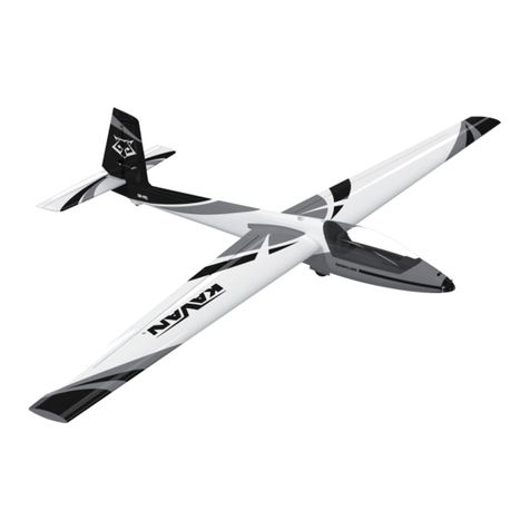
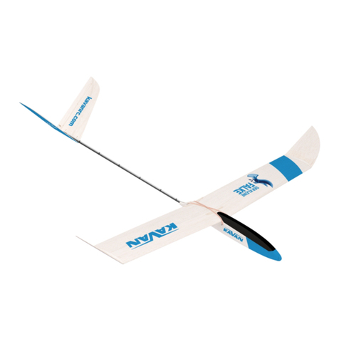
Kavan RESCO Kit V.2 User manual

www.kavanrc.eu
Instruction Manual/Návod ke stavbě/Bauanleitung
RESCO Kit V.2
High Performance Thermal Glider / Electric Glider
Vysokovýkonný termický větroň/motorový větroň
Der leistungsstarke Thermik-Segler / Motorsegler
Rev. 2: 08/2020

2
PRECAUTIONS:
This R/C model is not a toy. Use it with care and stricktly following the instructions in this manual.
Assemble this model following stricktly these instructions. DO NOT modify or alter the model. Failure to do so, the
warranty will lapse automatically. Follow the instructions in order to obtain a safe and solid model at the end of
the assembly.
Children under the age of 14 must operate the model under the supervision of an adult.
Assure that the model is in perfect conditions before every ight, taking care that all the equipment works correct-
ly and that the model is undamaged in its structure.
Fly only in days with light breeze and in a safe place away from any obstacles.
UPOZORNĚNÍ:
Tento RC model není hračka. Je určen k provozování osobami staršími 15 let.
Model dokončete a připravte k letu PŘESNĚ podle návodu. Model NEUPRAVUJTE, v opačném případě automaticky
ztrácí záruka svoji platnost.
Model provozujte opatrně a ohleduplně, důsledně se řiďte pokyny v tomto návodu.
Před každým letem se ujistěte, že model je v prvotřídním stavu, dbejte, aby všechny části pracovaly správně, a
model nebyl poškozený.
S modelem létejte na vhodné ploše bez překážek, stromů, elektrických vedení apod. Vyhledejte bezpečné místo,
mimo cesty a veřejné komunikace, dbejte na bezpečnost přihlížejících diváků.
VORSICHTSMAßNAHMEN:
Dieses R/C Modell ist kein Spielzeug. Benutzen Sie es mit Vorsicht und halten
Sie sich an die Anweisungen in dieser Anleitung. Bauen Sie das Modell gemäß der Anleitung zusammen. Modi-
zieren und verändern Sie das Modell nicht. Bei Nichteinhaltung erlischt die Garantie. Folgen Sie der Anleitung um
ein sicheres und haltbares Modell nach dem Zusammenbau zu erhalten.
Kinder unter 14 Jahren müssen das Modell unter Aufsicht eines Erwachsenen betreiben.
Versichern Sie sich vor jedem Flug, dass das Modell in einwandfreiem Zustand ist, dass alles einwandfrei funktio-
niert und das Modell unbeschädigt ist.
Fliegen Sie nur an Tagen mit leichtem Wind und an einem sicheren Platz ohne Hindernisse.
Electric Version/Verze elektro/ Version mit Elektroantrieb
Motor ESC/Regulátor/
Regler Propeller Battery/Akumulátor/
Akkumulator
ARAY G3 C2826-1000
RAY G2 R20A
9x5“ 3S LiPo RAY G4 450mAh/11.1V
BRAY G3 C2826-1400 8x5“ 2S LiPo RAY G4 450mAh/7.4V
CFOXY G3 C2208-1000 9x5“ 3S LiPo RAY G4 450mAh/11.1V
DFOXY G3 C2208-1200 9x5“ 2S LiPo RAY G4 450mAh/7.4V
Ask for KAVAN combo power sets for the RESCO kit.
K dispozici jsou rovněž pohonné sady KAVAN pro RESCO.
Fragen Sie nach KAVAN Combo Power Sets für das RESCO Kit.

3
RESCO Kit
High Performance Thermal Glider / Electric Glider
Designed and manufactured in the Czech Republic
Specication
Wingspan: 1990 mm
Length: 1240 mm
All-up Weight: 440g plus
Wing Section: modied AG
CG Position: 80 mm
Controls: Rudder, elevator, spoiler
Recommended RC Equipment
• Rudder and Elevator Servo: Hitec HS-53 2x
• Spoiler Servo: Hitec HS-65MG, Dymond D47
• Receiver Battery: Panasonic Eneloop AAA 800mAh 4.8
V pack
Warning!
This RC model you will build and y is not a toy! Althou-
gh it may seem to be light and slow in ight it is capable
of serious bodily harm and property damage.
It is your responsibility and yours alone - to build this
model correctly, properly install RC equipment and
motor and to test the model and y in accordance with
all safety standards (and common sense) as set down in
Safety Codes valid in your country.
If you are just starting RC modelling, consult your local
hobby shop or an experienced modeller in your local RC
club to nd a good instructor.
Precautions
You must build the model according to the instructions.
Do not alter or modify the model, as doing so may result
in an unsafe of unyable model. Take time to build stra-
ight, true and strong. Use proper radio and other equi-
pment that is in rst class condition, properly install all
the components and test their correct operation before
rst and any further ight. Fly the model only with com-
petent help from a well experienced modeller if you are
not already an experienced RC pilot.
Note: We, as the kit manufacturer, can provide you with
a top quality kit and instructions, but ultimately the qu-
ality and yability of your nished model depends on
how you build it; therefore we cannot in any way gua-
rantee the performance of your completed model, and
no representations are expressed or implied as to the
performance or safety of your completed model.
MODEL ASSEMBLY
Tail Surfaces
• Trial t the parts of the horizontal stabilizer, elevator,
n and rudder – no glue yet! Sand as necessary to ob-
tain perfect t (Fig. 1)
• Roughen the surface of the 3x0.5mm carbon spar
using No. 150 sandpaper and glue it with medium CA
to the trailing edge of the n. (Fig. 2)
• Glue together all the parts using medium CA or alipha-
tic resin (Fig. 3+4)
Recommended Glues
Unless stated otherwise, use medium thick cyanoacry-
late (CA) glue. D-box sheeting and wing ribs are better
to be glued using a water resistant white aliphatic resin
(alternatively, you can use this sort of glue for most of
wood-to-wood joints). The highly loaded parts (wing
roots, wing main spars, rewall etc.) should be glued to-
gether using 30 minute (or slower) epoxy oering high
strength and enough time for the correct positioning.
Tools and Accessories
• Very sharp modeller’s knife (e.g. Excel 16001 with No.
11 blades)
• Scissors
• Electric drill with drill bits
• Wire cutter
• Long nose pliers
• Screwdrivers
• Razor saw
• Sandpaper No. 80, 100, 180, 360-400
• Needle les
• Clothing pegs
• Modeller’s pins
• Epoxy mixing stick and vessel
• Masking tape, clear sticky tape
• Rubbing alcohol (for cleaning up excessive epoxy)
• Paper tissue or soft cloth (for cleaning up excessive epoxy)
• Straightedge with scale
• Square edge
• Thin clear plastic lm (for protecting the building plan)
• Permanent marker
• Modeller’s sealing iron, heat gun (for covering)
• Lightweight balsa ller

4
Fuselage (Glider Version)
• Trial t the parts of the fuselage– no glue yet! Sand as
necessary to obtain perfect t (Fig. 5)
• Glue the ply reinforcement and balsa triangle stocks
to the fuselage sides. Glue together the canopy. Glue
the canopy magnets before nal sanding; please do
not forget to check and mark the polarity of magnets
rst – they must attract each other. (Fig. 6+7)
• Glue together the front part of the fuselage; do not for-
get to sand the edges of the formers to the shape. (Fig. 8)
• Epoxy the wing nut plate with nuts already glued and
the tail boom holding formers in place (Fig. 7+8)
• Glue the nose cone parts in place and sand them to the
required shape using the supplied template. (Fig. 8+9)
• Partially cut (ca 1 mm deep) and crack the fuselage
sides along the rear edge of the rear fuselage former
in order to create a conical transition between the fu-
selage and the tail boom (the cut line is to be soaked
with thin CA before the nal sanding). Slide the tail
boom fairing ring and the rear fuselage ring onto the
tail boom tube (on the end without notches). Insert
the tail boom into the fuselage (no glue yet – it will
be glued only after the nal sanding and covering of
the fuselage). Trial t all the parts and sand carefully to
obtain a tight t; the fairing matching the rear edge of
the fuselage. The rear fuselage ring tack glue to the fu-
selage (do not glue it to the tail boom) and the fairing
ring glue to the tail boom. (Fig. 10+11)
• Glue the upper and lower sheeting of the fuselage; do
not forget to epoxy the tow hook plate. (Fig. 9+10+11)
• Attach the canopy to the fuselage and sand eve-
rything smooth. (Fig. 9+10+11)
• Locate the towhook; cut the opening for it in the lower
part of the fuselage and drill the holes for the xing
screws. (Fig. 12)
• Assemble (no glue yet) the horizontal tailplane py-
lon consisting of the liteply core with tailplane xing
nuts (M4 front, M3 rear), 4 mm balsa sides and liteply
tailplane seat. Insert the pylon into the corresponding
notch in the fuselage; trim if necessary, open up the
elevator push rod tunnel. Once satised, epoxy to-
gether the liteply core with the balsa sides and sand to
shape using the supplied liteply jig. Epoxy the tailpla-
ne seat in place. (Fig. 47A+47B+47C)
Fuselage (Electric Version)
• The building sequence of the electric version fuselage
is basically the same as with the glider version except
for the rewall and nose. Epoxy the rewall in place
and sand the nose to the desired shape matching your
spinner. (Fig. 13-15)
• Before you epoxy the rewall in, make sure the ope-
nings and holes in the rewall match your motor –
make any changes as necessary or cut a new rewall
to match your motor perfectly. (Fig. 13)
Wing Centre Section
• Epoxy together the wing central ribs; insert 3 mm beech
dowels into the holes in order to obtain correct match.
Note: Make a left and right pair of ribs. (Fig. 16+17)
• Epoxy the wing xing bolt plate between the central
ribs. (Fig. 18)
• Epoxy together the parts of the main spar shear web-
bing; the short 0.8 mm ply joiner (with a hole in the
centre) to the front side, the long joiner to the rear
side. Make bays for the wing carbon joiner; epoxy to-
gether front (shorter) 0.8 mm ply plate, 5 mm ply cen-
tral plate and rear 0.8 mm ply (longer, slanted edge)
plate. Prevent the epoxy hardening inside the bays –
put the parts together with the carbon joiner inserted,
then immediately remove the joiner (do not forget
cleaning the joiner using a paper tissue and rubbing
alcohol before the glue sets). (Fig. 19-22)
• Slide all ribs onto the mains spar shear webbing (no
glue yet!). Bind the joiner bays with the provided Ke-
vlar thread and soak with medium CA. (Fig. 23+24)
• Insert the rear spar, trial t the leading and trailing
edges. Sand to t if necessary. Once satised with the
t, glue all the parts of the wing centre section with
medium cyano over the building plan protected with
a sheet of thin clear plastic lm (you might nd better
gluing ribs to the main spar shear webbing with an ali-
phatic resin). (Fig. 25-27)
• Glue the lower 8x2 mm spruce stick main spar in place.
• Edge glue together the upper D-box sheeting (1.5 mm
balsa) and the upper 8x2 mm spruce stick main spar;
once cured glue it to the wing using aliphatic resin.
(Fig. 28-29)
• Bevel both two end ribs of the wing centre section
using the supplied 7° dihedral jig. Then glue the 3 mm
liteply end ribs with magnets. (Fig. 30)
• Glue the airbrake frame to the upper side of the wing
and sheet the space between the central ribs with 1.5
mm balsa. Cut the openings for the wing xing bolts.
(Fig. 31)
• Epoxy the central half rib with the wing alignment pin
and sheet the space between the central ribs with 1.5
mm balsa. Cut the openings for the wing xing bolts.
(Fig. 32)
• Glue the reinforcements square to the 2.5 mm balsa
airbrake. (Fig. 33)
• Fine sand the entire wing centre section (incl. the air-
brake).
Wing Outer Panels
• The wing outer panels are to be constructed in the
same manner as the wing centre section; the main dif-
ference is that the inner part and the outer winglet are
built as one part on a at surface. Once the structure
is nished, you will cut it between the end/root ribs,
bevel to obtain the correct dihedral and glue together.
(Fig. 34+35)
• Glue together both two wing outer panels over the
building plan protected with a sheet of thin clear plas-
tic lm (remember – you are building left and right
wing panels!). Please note the inner spars are made

5
of spruce sticks, whilst the winglet spars are made of
balsa sticks.
• Glue the wing tips; bevel the ends of the main spar
sticks and glue them to the wing tips. (Fig. 36+37)
• Glue 2.5 mm balsa triangular wing gussets. (Fig.
38+39)
• Fine sand the entire wing outer panels.
• Cut o the outer winglets between the end ribs; bevel
the end ribs using the supplied 8° dihedral jig. (Fig. 40)
• Epoxy the wing panels and winglets together. (Fig. 41)
• Bevel the root ribs of the wing outer panels using the
supplied 7° dihedral jig. Trial t the carbon wing joiner
into the respective bays; there should be a tight t, no
play. If there is a signicant play, put some epoxy to
appropriate area of the joiner and sand as necessary
once the glue hardens. (Fig. 42+43)
• Glue the 3 mm liteply root ribs with 3 mm beech
alignment pins. (Fig. 44+45)
• Prepare everything for the airbrake servo installation;
glue the breglass plate to the lower surface of the air-
brake and the liteply magnet holder to the rear of the
servo bay. (Fig. 46)
• The spoiler servo is to be installed using a balsa spa-
cer (not supplied in the kit) - depending on the di-
mensions of your servo. The spacer + servo must not
be higher than the wing ribs; it may not obstruct the
spoiler when closed (do not forget to take in account
the double sided foam tape you will use to secure the
servo!). Apply epoxy or medium cyano to the servo
spacer (if used) and the entire balsa lower sheeting
of the servo bay in order to be sure the double sided
foam tape will stick.
Covering
• Thoroughly sand the surface of all parts with No. 360-
400 sandpaper and carefully vacuum all the dust (the
iron-on lm does not stick well to a dusty surface; the
dust also contains hard grains released o the sandpa-
per capable to ruin the smooth coating of your sealing
iron quickly).
• Use as light iron-on lm as you can get (transparent
Oracover, Oralite etc. – not supplied in the kit). Follow
the instruction manual supplied with the covering lm
of your choice please.
Hinging the Control Surfaces
Use strips of a high quality hinging tape (available in
hobby shops) or strips of the same iron-on lm you used
for the covering. Remember to apply the tape with the
control surface deected to the limit in order to get free
movement of the particular control surface.
Tail Surfaces and Tail Boom Installation
• Attach the wing centre section to the fuselage and
the horizontal tailplane to the tailplane pylon; secu-
re them with nylon bolts. Insert the tail boom with
attached horizontal tailplane into the fuselage (no
glue yet). Check again that the fuselage is straight;
align the wing and the tailplane with their trailing ed-
ges parallel. Once satised, epoxy the tail boom and
the tailplane pylon in place. Before the glue hardens
double check the correct alignment of the wing, fuse-
lage and tailplane.
• Carefully cut the end of the tail boom in order to open
the notch for the n (trim as necessary – beware of
cracking the tube). Use medium CA to glue the n into
the tail boom; be sure it is square to the horizontal
tailplane.
Pushrod Installation (Fig. 47D)
• Tack glue the pushrod tubes to the 1.5 mm balsa
pushrod tube holder.
• Tack thick cyano to the balsa and insert the pushrod
tubes into the carbon fuselage tube (with a little help
of pushrod strings).
• Insert the pushrod strings into the respective tubes
from the tail end.
Servo Installation
Rudder and Elevator Servos Installation (Fig. 48)
• Make a „Z“ bend on the end of the pushrod and t it
to the servo horn.
• Alternatively you can use a closed loop of a Kevlar thread
(not supplied in the kit) to hook the rudder – it might save
some weight. In that case you will need to install just one
pushrod for the elevator.
Spoiler Servo Installation (Fig. 49)
• The spoiler servo is to be installed using a balsa spacer
(not supplied in the kit). The thickness of the spacer
depends on the dimensions of your servo. The spacer
+ servo must not be higher than the wing ribs (in may
not obstruct the spoiler when closed).
• Glue the breglass plate to the spoiler.
• Glue the magnets to the spoiler and wing using the
supplied liteply holder.
• Please check the polarity of magnets rst – they must
attract each other.
Pushrods and Towhook (Fig. 50)
• The pushrod tubes are to be located over the liteply
plate.
• Thread them through the holes in the former next to
servos.
• Install the towhook to the pre-drilled holes.
Wing Root Rib (Fig. 51)
• Glue the magnets using 5min epoxy.
Pushrod Installation – The Tail End (Fig. 52)
• Trial t the rudder and elevator horns (no glue yet),
bend the ends of pushrod strings to the „L“ shape and
thread them through the hole in the horn. Once sa-
tised, cyano the horns into the rudder and elevator.
• Please note the servo arms have to be square to the
pushrods in the neutral.
• Glue the end of the rudder pushrod tube to the fuselage.
• The end of the elevator pushrod tube remains free, no
glue here.

6
FLYING
Be sure you are using fully charged batteries. Now (and
before any further ight again) check correct function
of whole radio equipment, motor and moving of cont-
rol surfaces. Be sure any part of ight equipment cannot
move during ight. We strongly recommend making a
range check (see your radio instruction manual for de-
tails).
The rst ight: Wait for a calm day. Fly only on a safe
site as a RC club ying eld. Glider will be very happy on
your favourite slope on a calm day. The very light lift will
allow perfect ne trimming out.
Glider: Switch your transmitter and then the receiver
on and check all the working systems one more. Fa-
cing INTO the wind hold your transmitter in one hand;
grip the model in the other hand near the centre of
gravity. Hold it at head level and give the model a
fairly powerful push exactly into wind; wings level,
nose slightly down. Your model should now glide in a
long, at and straight path without needing any help
from you. Use the controls gently if necessary, and
adjust the trim tabs until your RESCO glides above
described way. Now check the position of control sur-
faces; set length of pushrods to bring back trim tabs
on your transmitter to central position if necessary
(we strongly recommend doing it in any way). Check
again gliding of your RESCO. Now you are ready to
make your rst bungee launch. Always use a bungee
set appropriate to the size (100-150 m) and weight of
your model!
Electric version: Switch your transmitter and then
the receiver on and check all the working systems
once again. Launch your RESCO with throttle fully
open INTO the wind. During climbing be gentle on
the controls, try to keep the model ying into the
wind until you have about 100-150 metres of altitude.
Climb slowly - too steep climbing may cause the
model will stall and fall to the ground. You are at 150
metres - this is time to trim out your RESCO at full
power. After everything is OK - it means the model at
approx. 50-60% of full throttle ies straight without
turning, descending or ascending (if your RESCO alre-
ady tends to ascend you will have to increase motor
down thrust), turn the motor o and test RESCO’s
gliding characteristics.
Keep your RESCO into the wind and observe its ight.
If turns without power right (although under power it
kept the straight direction) it will be necessary to increa-
se motor right side thrust and vice versa. If descends too
much without power (although under power it kept the
level ight) you will have to increase motor down thrust
(assuming the centre of gravity is correct! - check it after
landing).
Final Fine Tuning
During next ights trim out your RESCO to nd optimal
setting - safe climbing and good gliding - it is a compro-
mise, of course. You might nd useful programming a
spoiler->elevator mix (if your radio allows) that will eli-
minate the nose pitching when the spoiler is deployed.
In general the CG position should be located between
78-82 mm behind the wing leading edge. By moving
the CG back you get better gliding performance whilst
reducing the stability. It makes your model more sen-
sitive on controls and increases the model reaction on
thermal. The back CG position makes the model more
dicult to y and requires more attention from you,
while a nose heavy model is easier to y but you will
lack the performance. We recommend starting with the
CG at 78 mm behind the leading edge. Beyond 82 mm
the increasing lack of stability prevails over the gain of
gliding performance.
Enjoy your new RESCO, have a ball!
Towhook (Glider Version) (Fig. 53)
• Keep the recommender CG position 78 – 82 mm be-
hind the wing leading edge.
• Set the towhook 10 mm in front the CG for the rst
ight.
• You have to loose the front screw in order to move the
towhook.
Power System Installation (Electric Version)
(Fig. 54-56)
• Fit your motor using appropriate screws to the re-
wall; secure the ESC and power pack using Velcro tape
into the cockpit. With your RC set on test whether the
motor rotates in the correct direction (counter cloc-
kwise when looking from the front) If it not the case,
change the setting of your ESC or swap any two of the
three cables between the motor and ESC. Fit 30 or 32
mm spinner with blades corresponding to your motor
and battery set-up.
Spoiler (Fig. 57)
• The servo must be located as high as possible – as clo-
se to the spoiler as possible.
• Install the servo using double sided foam tape.
Recommended Control Surface Throw, CG Po-
sition (Fig. 58)
• CG Position: 78-82 mm
• Rudder: ±60 mm
• Elevator: ±10 mm
• Spoiler: -40 mm
• Brake->Elevator mix: -5 mm elevator at full spoiler

7
RESCO Kit
Vysokovýkonný termický větroň/motorový větroň
Zkonstruováno a vyrobeno v České republice
Technické údaje
Rozpětí: 1990 mm
Délka: 1240 mm
Letová hmotnost od: 440g
Prol: modikovaný AG
Poloha těžiště: 80 mm
Ovládané funkce: Směrovka, výškovka, brzda
Doporučené vybavení
• Servo VOP a SOP: Hitec HS-53 2x
• Servo brzdy: Hitec HS-65MG, Dymond D47
• Akumulátor: sada Panasonic Eneloop AAA 800mAh
4,8 V
Upozornění!
RC model, který budete stavět a létat, není hračka! Ačko-
liv Vám může připadat lehký a pomalý v letu, je schopen
při nesprávném zacházení způsobit vážné zranění nebo
poškození majetku. Je na Vás a jen na Vás, zda postavíte
model správně, správně instalujete RC soupravu a mo-
tor a model zalétáte a dále budete létat v souladu s běž-
nými zvyklostmi a pravidly (a také selským rozumem).
Pokud právě začínáte s RC modely, požádejte o radu ve
Vašem modelářském obchodu nebo zkušeného mo-
deláře v místním modelářském klubu tak, abyste našli
dobrého instruktora.
Před stavbou
Model stavte přesně podle návodu. Neměňte nebo ne-
upravujte model, protože pokud tak učiníte, riskujete,
že model může být nebezpečný nebo neovladatelný.
Najděte si čas pro stavbu, stavějte vše pevně a spoleh-
livě. Použijte odpovídající RC soupravu a další vybavení,
které je v prvotřídním stavu; správně instalujte všechny
části modelu a přezkoušejte jejich činnost a fungování
před prvním a každým dalším letem. Pokud nejste zku-
šený RC pilot, létejte jen s pomocí zkušeného modeláře
Poznámka: My, jako výrobce stavebnice Vám můžeme
zaručit stavebnici prvotřídní kvality s podrobným návo-
dem, ale letové vlastnosti a výkony závisí výhradně na
tom, jak model dokončíte Vy. Protože nemáme žádnou
kontrolu nad tím, jak model dokončíte, nemůžeme pře-
vzít (a nemůže být ani předpokládána) jakoukoliv odpo-
vědnost za případné škody způsobené nebo související
s provozem Vámi dokončeného modelu.
Doporučená lepidla
Pokud není výslovně uvedeno jinak, díly lepte středním
vteřinovým lepidlem. Tuhý potah torzní skříně křídla a
žebra je vhodné lepit voděodolným disperzním lepidlem
(alternativně můžete disperzním lepidlem lepit všechny
spoje dřevo-dřevo kromě pevnostních). Pevnostní spoje
(kořenové části křídla, nosníky atd.) lepte 30minutovým
epoxidovým lepidlem, které má vysokou pevnost a po-
skytuje dostatek času na přesné slícování dílů.
Nářadí a pomůcky
• Velmi ostrý modelářský nůž s výměnnými čepelemi
(např. Excel 16001 s čepelemi č. 11)
• Nůžky
• Elektrická vrtačka se sadou vrtáků
• Štípací kleště
• Kleště s plochými tenkými čelistmi
• Šroubováky ploché a křížové
• Žiletková pilka
• Brusný papír 80, 100, 180, 360-400
• Sada jehlových pilníků
• Kolíčky na prádlo, kancelářské nebo truhlářské svorky
• Modelářské špendlíky
• Tyčinka a nádobka na míchání epoxidu
• Maskovací páska, isolepa
• Denaturovaný líh (pro otírání nadbytečného epoxidu)
• Papírový ubrousek nebo čistý hadřík (pro otírání nad-
bytečného epoxidu)
• Ocelové pravítko
• Pravoúhlý trojúhelník
• Tenká průhledná polyetylénová fólie
• Lihový značkovač s tenkým hrotem
• Modelářská žehlička a popř. horkovzdušná pistole pro
potahování nažehlovací fólií
STAVBA MODELU
Ocasní plochy
• Připravte si a na sucho bez lepení slícujte díly ocasních
ploch; dle potřeby zabruste. (Obr. 1)
• Brusným papírem č. 150 lehce zdrsněte povrch uhlíko-

8
vé pásnice 3x05 mm a nalepte ji středním vteřinovým
lepidlem na odtokovou hranu kýlovky. (Obr. 2)
• Všechny díly slepte dohromady středním vteřinovým
nebo disperzním lepidlem. (Obr. 3+4)
Trup (verze větroň
• Připravte si a na sucho bez lepení slícujte díly trupové
gondoly; dle potřeby zabruste. (Obr. 5)
• Na bočnice přilepte překližkové výztuhy a balsové
trojúhelníkové lišty. Slepte a zkompletujte kryt kabiny.
Magnety uzávěru kabiny přilepte ještě před brouše-
ním; nezapomeňte předem vyzkoušet, zda se páry
magnetů přitahují. (Obr. 6+7)
• Slepte přední část trupové gondoly, přepážky nezapo-
meňte zbrousit do úkosu. (Obr. 8)
• Epoxidem vlepte desku se zalepenými maticemi upev-
ňovacích šroubů křídla a přepážky sloužící k upevnění
ocasního nosníku. (Obr. 7+8)
• Vlepte díly nosu trupu a opracujte do správného tvaru
s pomocí dodávané šablony. (Obr. 8+9)
• Nařízněte (do hloubky cca 1 mm) a opatrně nalomte
obě bočnice podél hrany zadní přepážky tak, abyste
vytvořili kónický přechod pro trubkový ocasní nosník
(místo lomu před závěrečným přebroušením prosyťte
řídkým vteřinovým lepidlem). Na přední část ocasního
nosníku (bez zářezů) nasuňte kruhový přechod a kru-
hovou přepážku zakončení trupové gondoly. Trubku
nosníku zasuňte do trupu (zatím nelepte – až po pota-
žení trupu). Všechny díly pečlivě slícujte a zabruste tak,
aby ocasní nosník šel těsně zasunout do trupu a jeho
přechod plynule navazoval na trupovou gondolu. Pře-
pážku zakončující gondolu opatrně přilepte k bočni-
cím (dbejte, abyste ji nepřilepili k ocasnímu nosníku)
a přechod přilepte k ocasnímu nosníku. (Obr. 10+11)
• Nalepte horní a spodní tuhý potah (nezapomeň-
te epoxidem vlepit desku pro vlečný háček). (Obr.
9+10+11)
• Nasaďte kryt kabiny a celou gondolu na jemno za-
bruste tak, aby všechny části včetně přechodu ocasní-
ho nosníku plynule navazovaly. (Obr. 9+10+11)
• Připravte si vlečný háček a vyřízněte otvor pro něj ve
spodku trupu a vyvrtejte otvory pro upevňovací šrou-
by. (Obr. 12)
• Na sucho, bez lepení sestavte pylon vodorovné ocas-
ní plochy (VOP) z překližkového jádra se zasunutými
hliníkovými maticemi pro upevňovací šrouby VOP (M4
vpředu, M3 vzadu) s balsovými bočnicemi a překližko-
vým sedlem. Pylon zkusmo zasuňte do drážky v ocas-
ním nosníku, dle potřeby zabruste a upravte kanál pro
trubici lanovodu výškovky. Jakmile jste spokojeni, jád-
ro a bočnice pylonu slepte dohromady epoxidem a za-
bruste dle obrázku s pomocí dodávané šablony. Nako-
nec epoxidem přilepte sedlo VOP. (Obr. 47A+47B+47C)
Trup (verze elektro)
• Stavba trupu verze elektro je obdobná stavbě trupu
pro větroň s vyjímkou přídě, do níž se vlepí motorová
přepážka. Příď poté zabruste do správného tvaru na-
vazujícího na vrtulový kužel. (Obr. 13-15)
• Před zalepením motorové přepážky se ujistěte, že
otvory v ní odpovídají vašemu motoru – dle potřeby
upravte nebo v krajním případě zhotovte novou, přes-
ně na míru vašemu motoru. (Obr. 13)
Střední část křídla (centroplán)
• Epoxidem k sobě slepte žebra středu křídla; pro přes-
né slícování zasuňte kolíky do připravených 3 mm
otvorů. Pozor: Vytvořte zrcadlově shodný pár žeber.
(Obr. 16+17)
• Mezi připravená středová žebra epoxidem vlepte des-
ku pro upevňovací šrouby křídla. (Obr. 18)
• Epoxidem slepte díly stojiny hlavního nosníku; krát-
kou 0,8 mm překližkovou spojku s otvorem ve středu
na přední stranu hlavního nosníku, dlouhou spojku na
zadní stranu hlavního nosníku. Na koncích stojiny nos-
níku vytvořte kapsy pro uhlíkové spojky z kratší obdél-
níkové 0,8mm překližkové desky vpředu, středového
dílu z 5 mm překližky a delší 0,8 mm překližkové desky
se šikmo seříznutým koncem vzadu. Dbejte, aby do
prostoru kapsy nepronikl nadbytečný epoxid – lepte
se zasunutou uhlíkovou spojkou, kterou vyjmete po
přiložení dřevěných dílů k sobě (nezapomeňte ji ihned
otřít papírovým ubrouskem namočeným v denaturo-
vaném lihu). (Obr. 19+20+21+22)
• Všechna žebra nasuňte na stojinu hlavního nosníku
(zatím nelepte!). Kapsy pro spojky křídla oviňte kevla-
rovou nití a prosyťte středním vteřinovým lepidlem.
(Obr. 23+24)
• Nasuňte pomocný zadní nosník, slícujte náběžnou a
odtokovou lištu. Dle potřeby zabruste. Jakmile všech-
ny díly uspokojivě lícují, můžete střední část křídla
slepit středním vteřinovým lepidlem na plánku polo-
ženém na rovné desce a chráněném tenkou polyetylé-
novou fólií (žebra je vhodnější ke stojině hlavního nos-
níku přilepit disperzním lepidlem). (Obr. 25+26+27)
• Nalepte spodní pásnici hlavního nosníku ze smrkové
lišty 8x2 mm.
• K hornímu tuhému potahu torzní skříně po délce na
tupo přilepte horní pásnici hlavního nosníku ze smr-
kové lišty 8x2 mm a celek nalepte na křídlo disperzním
lepidlem. (Obr. 28+29)
• Koncová žebra střední části křídla zabruste do úkosu
s pomocí dodávané šablony 7°. Poté nalepte koncová
žebra z 3 mm topolové překližky s vlepenými magne-
ty. (Obr. 30)
• Na horní stranu střední části křídla nalepte obvodový
rámeček aerodynamické brzdy a tuhý potah z 1,5 mm
balsy mezi středová žebra s vyříznutými otvory pro
upevňovací šrouby křídla. (Obr. 31)
• Epoxidem vlepte středové položebro s upevňovacím
čepem křídla a 1,5 mm balsou vylepte prostor mezi
středovými žebry zdola. (Obr. 32)
• Na spodní stranu brzdy z 2,5 mm balsy nalepte kolmé
výztuhy. (Obr. 33)
• Celou střední část křídla na jemno přebruste (vč. brzdy).

1 2 3
456 7
8910 11
9

12 13 14
15 16 17 18 19
20 21 22 23
10

24 25 26 27
28 29 30
31 32
11

33 34 35
36 37
38 39 40
12

13
41 42
43 44 45
46 47A 47B

14
48 49
50 51
47C 47D 47E

52 53
15
55 5654

16
57 58
Fibreglass plate 0.8 mm/Podložka laminát 0,8 mm/
Laminatunterlage 0,8 mm
CG Position: 78-82 mm
Těžiště: 78-82 mm
Schwerpunkt: 78-82 mm • The spacer thickness depends on the dimensions of the servo used. The servo must be located as high
as possible – as close to the spoiler as possible.
• Výšku podložky volte dle šířky krabičky serva. Servo musí být co nejvýše – co nejblíže k brzdě.
• Die Höhe der Unterlage wählen Sie nach der Breite der Servo-Schachtel. Servo muss möglichst hoch
und möglichst nahe bei der Bremse sein.
CG Position: 78-82 mm
Těžiště: 78-82 mm
Schwerpunkt: 78-82 mm
10 mm
±10 mm
-40 mm (ca. 75°)
±60 mm

17
Vnější díly křídla (uši)
• Vnější části křídla (uši) se staví podobně jako středová
část křídla s tím, že ucho a koncový winglet se staví
vcelku; po slepení kostry se mezi koncovými žebry
rozřízne a žebra se zabrousí do úkosu pro vytvoření
požadovaného vzepětí. (Obr. 34+35)
• Na plánku položeném na rovné desce a chráněném
tenkou polyetylénovou fólií slepte obě uši (pamatujte
– stavíte zrcadlově shodné levé a pravé ucho!). Nepře-
hlédněte, že vnitřní část ucha má hlavní a pomocný
nosník ze smrkových lišt, zatímco winglety je mají
balsové.
• Nalepte koncové oblouky; konce pásnic hlavního nos-
níku seřízněte do úkosu a přilepte ke koncovému ob-
louku. (Obr. 36+37)
• Vlepte trojúhelníkové výkližky z 2,5 mm balsy dle plá-
nu. (Obr. 38+39)
• Celé ucho přebruste a začistěte.
• Mezi koncovými žebry odřízněte vnější winglety a je-
jich kořenová žebra zkoste s pomocí dodávané šablo-
ny 8° pro vytvoření požadovaného vzepětí. (Obr. 40)
• Uši a winglety poté slepte k sobě. (Obr. 41)
• Kořenová žebra uší zkoste s pomocí dodávané šablo-
ny 7° pro vytvoření požadovaného vzepětí. Vyzkou-
šejte, zda uhlíkové spojky je možno do kapes ve stře-
dové části křídla a uších zasunout těsně a bez vůlí. Je-li
spojka volná, naneste na vhodná místa epoxid a po
vytvrzení zabruste dle potřeby. (Obr. 42+43)
• Nalepte vnější kořenová žebra uší a 3 mm vodící buko-
vé kolíky. (Obr. 44+45)
• Zkusmo nainstalujte servo brzdy; na spodní stranu
brzdy nalepte laminátovou podložku a; k zadnímu
okraji výřezu pro brzdu přilepte překližkový držák
magnetu. Zalepte pár magnetů do držáku na křídle a v
brzdě (musejí se přitahovat). (Obr. 46)
• Dle tloušťky použitého serva může být potřeba vlepit
balsovou podložku o takové tloušťce, aby horní strana
krabičky serva byla téměř v rovině s okrajem středo-
vého žebra (nezapomeňte počítat s tloušťkou pěnové
pásky, kterou použijete pro upevnění serva!). Aby pě-
nová lepící páska dobře držela, podložku serva a celý
tuhý potah mezi středovými žebry potřete epoxidem
nebo nasyťte vteřinovým lepidlem.
Potahování modelu
Všechny díly modelu, které budete potahovat, jemně
přebruste brusným papírem č. 400 a vysavačem z nich
poté pečlivě odstraňte prach (nažehlovací fólie špatně
drží na zaprášeném povrchu; prach navíc obsahuje zrn-
ka brusiva, která rychle zničí teonový povlak modelář-
ské žehličky).
Pro potah použijte co nejlehčí nažehlovací fólii (transpa-
rentní Oracover, Oralite apod. - není součástí stavebni-
ce). Při potahování se řiďte návodem k použití pro daný
materiál.
Závěsy kormidel
Pohyblivé ovládací plochy upevněte pomocí kvalitní
čiré samolepící pásky – vhodné pásky se prodávají v
modelářských obchodech, osvědčená je rovněž páska
3M Crystal Clear z papírnictví - nebo pomocí pruhů na-
žehlovací fólie, kterou jste použili pro potah. Pásku lepte
vždy na kormidlo vychýlené do krajní polohy, aby vznik-
la dostatečná vůle pro pohyb kormidla.
Upevnění nosníkuocasníchploch aocasníchploch
• Střední část křídla upevněte šrouby k trupové gondo-
le a vodorovnou ocasní plochu k pylonu VOP. Ocasní
nosník se zasunutým pylonem VOP na sucho, bez le-
pení zasuňte do trupové gondoly. Zkontrolujte při po-
hledu shora, zda je trup v podélné ose přímý a křídlo a
vodorovnou ocasní plochu ustavte tak, aby byly jejich
odtokové hrany rovnoběžné. Jakmile jste spokojeni,
ocasní nosník přilepte důkladně epoxidem k trupové
gondole; epoxidem rovněž zalepte pylon VOP. Před
vytvrzením lepidla znovu zkontrolujte správnost vzá-
jemné polohy křídla a vodorovné ocasní plochy.
• Opatrně odřízněte konec ocasního nosníku, abyste
otevřeli štěrbiny pro kýlovku – štěrbinu dle potřeby
upravte – pozor na roztržení trubky. Svislou ocasní
plochu vlepte středním vteřinovým lepidlem do ocas-
ního nosníku – dbejte, aby byla kolmá na vodorovnou
ocasní plochu.
Instalace lanovodů (Obr. 47D)
• Vodící trubice lanovodů uchyťte na pěti místech na
lehkou balsu tl. 1,5 mm.
• Na balsu bodově naneste husté vteřinové lepidlo a
pomocí drátů bowdenu nasuňte do uhlíkové trubky.
• Dráty jsou nasunuty zezadu do připravených otvorů.
Instalace serv
Serva směrovky a výškovky (Obr. 48)
• Drát lanovodu ohněte do „Z“a nasuňte na páku serva.
• Na směrovku můžete alternativně použít kevlarovou nit
(není součástí stavebnice), ušetříte nějaké gramy. V tom
případě pak stačí vlepit pouze jeden lanovod pro vodo-
rovnou ocasní plochu (VOP).
Montáž serva brzdy (Obr. 49)
• Servo je přilepeno na podložce z balsy. Výška podlož-
ky záleží na použitém servu. Podložka se servem ne-
smí být vyšší než žebro (nesmí vadit při zavření brzdě).
Lanovody a vlečný háček (Obr. 50)
• Lanovody musí procházet nad deskou z topolové pře-
kližky.
• Prostrčte je také připravenými otvory v přepážce před
servy.
• Vlečný háček namontujte do připravených otvorů.
Kořenová žebra křídla (Obr. 51)
• Magnety vlepte 5minutovým epoxidem.
Instalace lanovodů u ocasních ploch (Obr. 52)
• Páky kormidla lepte až po nasazení na drát lanovodu,
který ohnete do L.
• Páky serva musí být v nule (90° k drátu).
• Vnější trubice lanovodu směrovky je na kraji přilepená

k trubce trupu.
• Trubice lanovodu výškovky se nelepí.
Vlečný háček (verze větroň) (Obr. 53)
• Dodržte těžiště podle návodu 78 – 82 mm od náběžné
hrany křídla.
• Háček nastavte pro první lety 10 mm před těžiště.
• Pro nastavení je třeba povolit šroubek před háčkem.
Instalace pohonné jednotky (Obr. 54-56)
Motor upevněte vhodnými šrouby k motorové přepáž-
ce, regulátor otáček a pohonný akumulátor upevněte v
prostoru kabiny pomocí suchého zipu. Se zapnutou RC
soupravou vyzkoušejte, zda se motor otáčí ve správném
smyslu (proti směru hodinových ručiček při pohledu
zepředu). Pokud tomu tak není, přeprogramujte regu-
látor nebo prohoďte mezi sebou kterékoliv dva z trojice
kabelů mezi motorem a regulátorem. Poté upevněte
vrtulový kužel o průměru 30 nebo 32 mm s listy odpo-
vídajícími vašemu motoru a pohonnému akumulátoru.
Brzda (Obr. 57)
• Servo musí být co nejvýše – co nejblíže k brzdě.
• Na podložku je přilepte oboustrannou lepící páskou.
Doporučené velikosti výchylek ovládacích
ploch, těžiště (Obr. 58)
• Těžiště: 78-82 mm
• Směrovka: ±60 mm
• Výškovka: ±10 mm
• Brzda: -40 mm
• Mix brzda->výškovka: výškovka -5 mm při plné brzdě
LÉTÁNÍ
Ujistěte, že máte akumulátory plně nabité. Nyní (a před
každým dalším letem) kontrolujte správné fungování
celého letového RC vybavení, motoru a pohyby ovláda-
cích ploch. Ujistěte se, že žádná část vybavení se nemů-
že během letu samovolně pohybovat. Důrazně dopo-
ručujeme provést test dosahu RC soupravy v souladu s
pokyny výrobce.
První let: Počkejte si na den, kdy vane vítr pod 3 m/s
(slabý vánek). Létejte jen na bezpečném místě, jako je
letiště modelářského klubu. Větroň je dobré zalétávat
na svahu za velmi slabého větru, kdy proudění právě
tak umožňuje udržet se nad svahem, což pilota donutí
si důkladně pohrát s vytrimováním.
Větroň: Zapněte nejprve vysílač a potom přijímač a
znovu prověřte činnost RC soupravy. Model držte ve
výši hlavy skloněný přídí mírně k zemi a vypusťte je mír-
ným švihem proti větru (ještě lepší je svěřit vypuštění
modelu pomocníkovi, který to nedělá poprvé). Model
by měl klouzat v dlouhém přímém letu bez houpání,
bez nutnosti korekcí kormidly. Pokud je při zalétává-
ní třeba, korigujte let přiměřenými pohyby kormidel a
trimujte, dokud není kluz bezchybný. Nyní zkontrolujte
polohu ovládacích ploch; pokud je to nezbytné, nastav-
te délku všech táhel tak, aby trimy všech kanálů byly co
možná nejblíže středové poloze (doporučujeme učinit
tak, i když je Váš vysílač vybaven pamětí výchylek trimů).
Znovu zkontrolujte klouzavý let.
Nyní jste připraveni vykonat první start modelu RESCO
na vlečné šňůře nebo gumicuku. Doporučujeme vleč-
nou šňůru o délce 100-150 m s praporkem nebo gumi-
cuk odpovídající letové hmotnosti a rozpětí modelu.
Verze s elektrickým pohonem: Zapněte vysílač a
potom přijímač (regulátor) a zkontrolujte znovu funk-
ci celého modelu. Zapněte motor na plný plyn. Model
vypusťte je mírným švihem proti větru (dobré je udělat
přitom dva nebo tři kroky). Nechejte nejprve model
poodlétnout, nesnažte se jej nutit hned do stoupání.
Bystře reagujte kormidly, pokud je třeba, a vystoupej-
te s modelem do výšky 100-150 m. Stoupejte zvolna,
nespěchejte, předejdete tak přetažení modelu, ztrátě
rychlosti a pádu. Tak, a jste ve 150 metrech, je čas vytri-
movat RESCO při plném plynu. Jakmile je vše v pořádku,
tj. model při cca 30-40% plynu letí přímo bez zatáčení,
stoupání nebo klesání (pokud RESCO stále stoupá, bude
nutno zvětšit vyosení motoru dolů), vypněte motor a
otestujte RESCO za klouzavého letu.
Nasměrujte RESCO proti větru a sledujte jeho let. Pokud
zatáčí doprava (bez motoru), bude třeba zvětšit vyose-
ní motoru vpravo a naopak. Pokud (bez motoru) příliš
prudce klesá, bude třeba zvětšit vyosení motoru dolů
(předpokládáme, že těžiště je ve správné poloze – po
přistání zkontrolujte).
Konečné doladění: Během dalších letů RESCO vytri-
mujte do optimálního nastavení – bezpečný motorový
let s bystrým stoupáním a výborný kluz- je to samo-
zřejmě kompromis. Užitečným můžete shledat (pokud
to Vaše RC souprava dovoluje) mix, který vychýlením
výškovky potlačí klopivý moment způsobovaný vychý-
lením brzdy. Při přední poloze těžiště (78 mm) se RESCO
může zdát některým pilotům poněkud těžší na hlavu a
„tupé“ na řízení, ale zase je vhodné pro málo zkušené pi-
loty, kteří ještě nemají správně vyvinutý cit pro optimál-
ní velikost výchylek kormidel („moc za to tahají“). Nám
se při letových testech prototypů jako nejvhodnější jevi-
la poloha těžiště 78 mm, zkušený pilot si po zalétání mo-
delu může dovolit posunout těžiště ještě o něco více do-
zadu a bude odměněn jedinečnou reakcí na sebemenší
termický závan i citlivějším řízením. Při poloze těžiště 82
mm a dále za náběžnou hranou už začíná převažovat
negativní vliv ztráty stability nad ziskem klouzavosti.
Užijte si vaše nové RESCO, dobře se bavte!
18

19
RESCO Kit
Der leistungsstarke Thermik-Segler / Motorsegler
Entworfen und hergestellt in der Tschechischen Republik
Technische Daten
Spannweite: 1990 mm
Länge: 1240 mm
Fluggewicht ab: 440g
Prol: modizierte AG
Schwerpunktlage: 80 mm
Steuerbare Funktionen: Seitenleitwerk, Höhenleitwerk, Spoiler
Empfohlene Ausstattung
• Servo VOP a SOP: Hitec HS-53 2x
• Servo der Bremse: Hitec HS-65MG, Dymond D47
• Akkumulator: Set Panasonic Eneloop AAA 800mAh
4,8 V
Werkzeuge und Hilfsmittel
• Sehr scharfes Modellbaumesser mit auswechselbaren
Klingen (z.B. Excel 16001 mit Klinge Nr. 11)
• Schere
• Elektrische Bohrmaschine mit Bohrer-Satz
• Schneidezange
• Zange mit achen, dünnen Backen
• Flach- und Kreuzschraubendreher
• Laubsäge
• Schleifpapier 80, 100, 180, 360-400er Körnung
• Nadelfeilen-Set
• Wäscheklammern, Büroklammern, Schraubzwingen
• Modellbau-Stecknadeln
• Stäbchen und kleine Dose zum Epoxidmischen
• Abdeckband, klares Selbstklebeband
• Spiritus (zum Abwischen von überschüssigem Epoxid)
• Papierserviette oder ein sauberes Tuch (zum Abwis-
chen von überschüssigem Epoxid)
• Stahllineal
• Rechtwinkliges Dreieck
• Dünne transparente Polyethylen-Folie
• Alkoholmarker mit dünner Spitze
• Pro-Bügeleisen, bzw. Heißluftpistole für die Folien-
-Bespannung
Hinweis!
Das RC Modell, das Sie bauen und mit dem Sie iegen
werden, ist kein Spielzeug! Auch wenn es Ihnen beim
Fliegen leicht und langsam vorkommen kann, ist es
fähig, bei der falschen Benutzung eine ernsthafte Ver-
letzung oder einen Vermögensschaden zu verursachen.
Es liegt nur an Ihnen, ob Sie das Modell richtig bauen,
das RC Set und den Motor richtig installieren, das Modell
einiegen und weiter im Einklang mit üblichen Regeln
(und auch mit Bauernverstand) iegen werden. Wenn
Sie gerade mit RC Modellen beginnen, bitten Sie um
Rat in Ihrem Modellbaugeschäft oder einen erfahrenen
Modellbauer im lokalen Modellbauklub, damit Sie einen
guten Instruktor nden.
Vor dem Bau
Bauen Sie das Modell genau nach der Anleitung. Än-
dern Sie oder passen Sie das Modell auf keine Weise
an. Sonst riskieren Sie, dass das Modell gefährlich oder
unbeherrschbar sein kann. Finden Sie Zeit für den Bau,
bauen Sie alles fest und zuverlässig. Benutzen Sie ein
entsprechendes RC Set und andere Ausstattung, die im
perfekten Zustand ist; installieren Sie richtig alle Teile
des Modells und überprüfen Sie ihren Betrieb und Funk-
tionieren vor dem ersten und vor jedem nächsten Flug.
Wenn Sie kein erfahrener RC Pilot sind, iegen Sie nur
mit Hilfe eines erfahrenen Modellbauers.
Bemerkung: Wir, als Hersteller des Baukastens, können
Ihnen den Baukasten erstklassiger Qualität gewähr-
leisten, aber Flugeigenschaften und Leistungen sind
ausschließlich davon abhängig, wie Sie das Modell
fertig stellen. Da wir keine Kontrolle darüber haben, wie
Sie das Modell fertig stellen, können wir keine Verant-
wortung für etwaige Schäden übernehmen, die mit der
In-Betrieb-Setzung des von Ihnen fertiggestellten Mo-
dells verursacht wurden.
Empfohlene Klebstoe
Wenn nicht ausdrücklich anders angegeben, kleben
Sie die Teile mit einem mittelüssigen Sekundenkleber.
Das D-Box Brettchen des Flügels und der Rippen kleben
Sie mit wasserfestem Dispersionskleber (alternativ kö-
nnen alle HOLZ-HOLZ-Verbindungen mit Ausnahme der
Befestigungen mit einem Dispersionskleber geklebt wer-
den). Verkleben Sie die Festverbindungen (Flügelwur-
zeln, Holme, usw.) mit einem 30-minütigen Epoxidkleber,
der eine große Festigkeit aufweist und ausreichend Zeit
für die genaue Ausrichtung der Teile bietet.

20
Leitwerke
• Bereiten Sie die Leitwerksteile vor und richten Sie sie
aus, ohne sie zu verkleben; schleifen Sie nach Bedarf
(Abb. 1) mit einem Schleifpapier Nr. 150 um die Oberä-
che des Carbonstreifens 3x0,5 mm leicht aufzurauhen.
Kleben Sie diesen mit einem mittelüssigem Sekunden-
kleber auf die Hinterkante der Flosse. (Abb. 2)
• Kleben Sie alle Teile mit einem Sekunden–oder Dispersi-
onskleber zusammen. (Abb. 3+4)
Rumpf (Seglerversion)
• Bereiten Sie Teile der Rumpfgondel ohne Kleben vor
und richten Sie aus, nach Bedarf schleifen Sie. (Abb. 5)
Kleben Sie Sperrholzverstärkungen und Balsadreiec-
kleisten an die Bordwände. Verkleben und komplettie-
ren Sie die Kabinenhaube. Kleben Sie die Kabinenmag-
nete vor dem Schleifen an; Stellen Sie sich sicher, dass
die Magnetpaare sich anziehen. (Abb. 6+7). Verkleben
Sie die Vorderseite der Rumpfgondel, achten Sie darauf,
die Trennwände im Winkel zu schleifen. (Abb. 8)
• Mit Epoxid-Kleber kleben Sie die Platte mit den verkleb-
ten Muttern der Flügel- und Spantbefestigungsschrau-
ben, die zur Befestigung des Leitwerksträgers dienen.
(Abb. 7+8)
• Kleben Sie die Teile der Rumpfnase und bringen Sie sie
mit der mitgelieferten Schablone in die richtige Form.
(Abb. 8+9)
• Schneiden Sie (bis zu einer Tiefe von ca. 1 mm) und
brechen Sie beide Seitenwände vorsichtig entlang der
Kante der hinteren Trennwand so, um einen konischen
Übergang für den röhrenförmigen Leitwerksträger zu
schaen (sättigen Sie den Bruchpunkt vor dem end-
gültigen Nachschleifen mit einem dünnen Sekunden-
kleber). Stecken Sie den kreisförmigen Übergang und
die kreisförmige Trennwand des Rumpfgondelendes
auf den vorderen Teil des Leitwerksträgers ein (ohne
Kerben). Stecken Sie das Trägerrohr in den Rumpf ein
(kleben Sie es noch nicht - erst nach der Beschichtung
des Rumpfes). Alle Teile richten Sie sorgfältig auf und
schleifen Sie sie, so dass der Leitwerksträger genau in
den Rumpf passt und sein Übergang nahtlos der Rum-
pfgondel folgt. Kleben Sie die Trennwand, die die Gon-
del beendet, vorsichtig auf die Seitenwände (achten Sie
darauf, dass Sie sie nicht zum Leitwerksträger kleben)
und kleben Sie den Übergang auf den Leitwerksträger.
(Abb. 10 + 11)
• Kleben Sie die obere und untere feste Beplankung (ver-
gessen Sie nicht, die Hochstarthakenplatte mit dem
Epoxid-Kleber zu verkleben). (Abb. 9 + 10 + 11)
• Bereiten Sie den Hochstarthaken vor und schneiden Sie
ein Loch für ihn in die Rumpfunterseite und bohren Sie
Löcher für die Befestigungsschrauben. (Abb. 12)
• Setzen Sie die Kabinenabdeckung auf und schleifen Sie
die ganze Gondel fein, so, dass alle Teile, einschließlich
des Übergangs des Leitwerksträgers, reibungslos aufei-
nander folgen. (Abb. 9+10+11)
• Montieren Sie den Pylon des horizontalen Leitwerks
aus dem Sperrholzkern mit eingesteckten Aluminium-
muttern für die Befestigungsschrauben des horizonta-
len Leitwerks (M4 vorne, M3 hinten) mit Balsaseitenwän-
den und Sperrholzsattel. Versuchen Sie, den Pylon in die
Nut im Leitwerksträger einzuführen, schleifen Sie nach
Bedarf und önen Sie den Kanal für das Bowdenzugro-
hr des Höhenleitwerks. Wenn Sie zufrieden sind, kle-
ben Sie den Kern und die Seitenwände des Pylons mit
dem Epoxid-Kleber zusammen und schleifen Sie nach
der Abbildung mit der mitgelieferten Schablone. Zum
Schluss kleben Sie den Sattel des horizontalen Leitwerks
mit dem Epoxid-Kleber. (Abb. 47A+47B+47C)
Rumpf (Elektro-Version)
• Der Rumpfaufbau der Elektro-Version ähnelt dem Rum-
pfaufbau der Segler- Version, mit Ausnahme des Bugs,
in dem der Motorspant verklebt wird. SSchleifen Sie
dann den Bug nach dem Propellerspinner in die richtige
Form. (Abb. 13-15)
• Vor der Verklebung des Motorspanten versichern Sie
sich, dass die Löcher darin zu Ihrem Motor passen. Rich-
ten Sie die Löcher nach Ihrem Bedarf zu, oder als letzte
Möglichkeit, machen Sie neue, die genau zu Ihrem Mo-
tor passen. (Abb. 13)
Flügel-Mittelteil
• Kleben Sie die Rippen des Flügel-Mittelteils mit Epoxid
zusammen. Für eine genaue Ausrichtung stecken Sie
die Stifte in die vorbereiteten 3 mm- Löcher. Achtung:
Stellen Sie ein linkes und rechtes Rippenpaar her. (Abb.
16+17)
• Verkleben Sie mit Epoxid die Platte für die Befestigu-
ngsschrauben des Flügels zwischen den vorbereiteten
Mittelrippen. (Abb. 18)
• Kleben Sie mit Epoxid die Verbinder-Teile und die
Hauptholme zusammen; den kurzen 0,8 mm Sperr-
holzverbinder mit einem Loch in der Mitte an die Vorde-
rseite des Hauptholms, das lange Verbindungsstück an
die Hinterseite des Hauptholms.
• Am Ende der Holmkonstruktion stellen Sie die Gehäuse
für die Carbon-Verbinder her: die kürzere, rechteckige
0,8 mm Sperrholzplatte vorn am 5 mm Sperrholz-Mit-
telteil und die längere 0,8 mm Sperrholzplatte mit den
schräg geschnittenen Ende hinten.
• Lassen Sie kein überschüssiges Epoxid in den Gehäuse-
bereich eindringen- kleben Sie mit eingestecktem Car-
bon-Verbinder, den Sie entfernen, wenn Sie die Holztei-
le zusammenfügen. Vergessen Sie nicht, ihn sofort mit
einem in Spiritus getauchten Papiertuch abzuwischen.
(Abb. 19+20+21+22)
• Schieben Sie alle Rippen auf die Holmkonstruktion
(noch nicht kleben).
• Wickeln Sie die Gehäuse der Flügelverbinder mit Kevlar-
-Faden ein und benetzen Sie sie mit einem mittelüssi-
gen Sekundenkleber. (Abb. 23+24)
• Stecken Sie den hinteren Hilfsträger ein und richten Sie
die Nasenleiste und die Endleiste aus. Schleifen Sie nach
Bedarf. Sobald alle Teile gut passen, können Sie den mi-
BAU DES MODELLS
Table of contents
Other Kavan Toy manuals

Kavan
Kavan SAVAGE MAX User manual

Kavan
Kavan Bell Jet Ranger User manual

Kavan
Kavan Pilatus PC-6 Porter User manual

Kavan
Kavan Swift S-1 User manual

Kavan
Kavan ALPHA 1500 User manual

Kavan
Kavan TARA User manual

Kavan
Kavan FunStik User manual

Kavan
Kavan BETA 1400 RTF User manual

Kavan
Kavan CUMUL DLG User manual

Kavan
Kavan Wingo Instruction Manual
Popular Toy manuals by other brands

MGA Entertainment
MGA Entertainment Project MC2 SODA CAN ROBOT quick start guide

Hasbro
Hasbro MARVEL SPIDER-MAN WEB SHOTS quick start guide

Hasbro
Hasbro My Little Pony RC Rainbow Dash Plane user manual

REVELL
REVELL Heinkel He 177 A-6 & Hs293 Assembly manual

Hornby
Hornby CLASS 50 Operating and maintenance instructions

Samba
Samba Pike Precision 2 manual