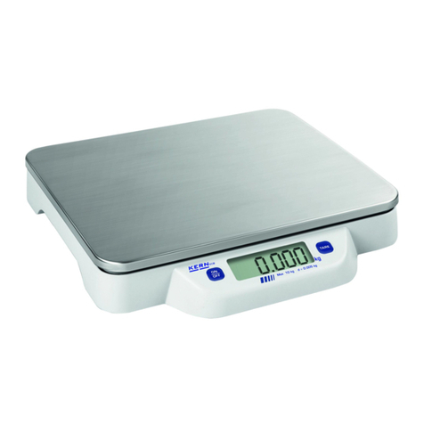
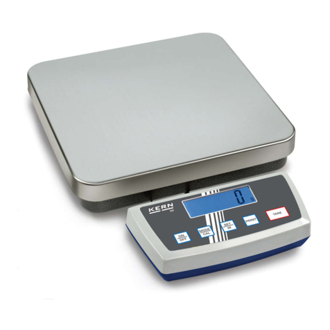
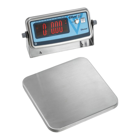
KERN EW User manual

KERN & Sohn GmbH
Ziegelei 1
D-72336 Balingen-Frommern
Tel: 0049-[0]7433- 9933-0
Fax: 0049-[0]7433-9933-149
Internet: www.kern-sohn.com
GB
Service Manual
Electronic Precision Balances
Page 2
KERN EW · EW-C · EG (N)
Version 2.2 01/2007
- 1 - EW_EW-C_EG_N-SH-e-0722

GB KERN EW · EW-C · EG (N)
Version 2.2
Service Manual
Electronic Precision Balances
1TOTAL VIEW ..........................................................................................................4
1.1 Total View Of EW Type - 220-12000g........................................................ 4
1.2 Total View Of EG Type - 220-620g, 2200g, 4200g..................................... 4
1.3 Total View Of EW-C Type - 600ct (120g)................................................... 5
1.4 Total View Of EW Type - 120g/0,0002g..................................................... 5
2ELECTRONIC CONSTRUCTION ...........................................................................6
2.1 Block Diagram.............................................................................................. 6
2.2 Whole Wiring................................................................................................ 7
3TROUBLESHOOTING............................................................................................8
3.1 Troubleshooting Procedure.......................................................................... 8
3.2 Trouble shooting Table................................................................................. 9
3.3 Primary Checks.......................................................................................... 10
3.4 Checks For Electric/Electronic Parts.......................................................... 11
4ADJUSTMENTS AND SETTINGS........................................................................12
4.1 Span Calibration (CAL) .............................................................................. 12
4.1.1 EW and EW-C Type............................................................................ 12
4.1.2 EG Type.............................................................................................. 13
4.2 Lock Switch................................................................................................ 14
4.3 Corner Error Adjustment ............................................................................ 15
4.3.1 EW – 120-1200 and EW-C Type......................................................... 15
4.3.2 EW – 2200-12K................................................................................... 16
4.4 Adjustment Sequence For Cases............................................................... 17
4.5 Resetting Address Data (Coefficients) ...................................................... 18
4.6 How To Call Address Mode/How To Re-write Address Data ..................... 19
4.7 Linearity Adjustment................................................................................... 20
4.8 Calibration Of Built-In Weight (Ref Cal)...................................................... 23
5PARTS REPLACEMENTS....................................................................................25
5.1 How to remove the case............................................................................. 25
5.1.1 EW 220-1200...................................................................................... 25
5.1.2 EW 2200-12K...................................................................................... 26
5.1.3 EW-C .................................................................................................. 27
5.1.4 EW 120-4 NM...................................................................................... 28
- 2 - EW_EW-C_EG_N-SH-e-0722
5.2 How To Cover The Case............................................................................ 29
5.2.1 EW 120-1200 and EW-C..................................................................... 29
5.2.2 EW 2200-12K...................................................................................... 29
5.3 Sequence Of Mechanism Unit Replacement.............................................. 30
5.3.1 How To Remove The Weighing Mechanism Unit................................ 31
5.3.2 How To Install Weighing Mechanism.................................................. 33
5.4 Plate Rib Replacement............................................................................... 34
5.4.1 Plate Rib Replacement Procedure...................................................... 35
5.5 Sequence Of Tuning-Fork Sensor Replacement........................................ 36
5.5.1 How to uninstall Tuning-fork assy ....................................................... 36
5.6 Sequence Of The AJDP Circuit Board Replacement ................................. 37
5.6.1 How To Remove AJDP Circuit Board.................................................. 37
5.6.2 How To Install AJDP Circuit Board...................................................... 38
5.7 How To Remove Calibration Weight Unit................................................... 39
5.7.1 EG 220-620......................................................................................... 39
5.7.2 EG 2200-4200..................................................................................... 39
5.8 How To Install Calibration Weight Unit....................................................... 41
6INSTALLATION OPTIONS...................................................................................42
6.1 Installation Of Battery Option ..................................................................... 42
6.1.1 EW 120-1200 and EW-C..................................................................... 42
6.1.2 EW 2200-12K...................................................................................... 43
7PARTS LIST..........................................................................................................44
7.1 EW 220-1200 ............................................................................................. 44
7.2 EW 2200-12K............................................................................................. 45
7.3 EW-C / EW 120-4 NM................................................................................ 46
- 3 - EW_EW-C_EG_N-SH-e-0722

1 Total View
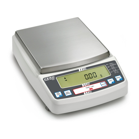
1.1 Total View Of EW Type - 220-12000g
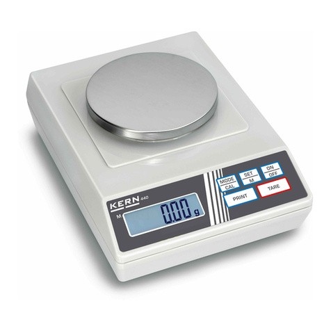
1.2 Total View Of EG Type - 220-620g, 2200g, 4200g
- 4 - EW_EW-C_EG_N-SH-e-0722

1.3 Total View Of EW-C Type - 600ct (120g)
1.4 Total View Of EW Type - 120g/0,0002g
- 5 - EW_EW-C_EG_N-SH-e-0722

2 Electronic Construction
2.1 Block Diagram
EG
EG
AC Adaptor
- 6 - EW_EW-C_EG_N-SH-e-0722

2.2 Whole Wiring
EG
EG
- 7 - EW_EW-C_EG_N-SH-e-0722

3 Troubleshooting
3.1 Troubleshooting Procedure
- 8 - EW_EW-C_EG_N-SH-e-0722

3.2 Trouble shooting Table
Symptoms Causes & Remedy
No display lights on. 1. AJDP board is defective.
2. AC adapter is defective.
3. Wrong connection of connection cords inside.
4. Built-in battery (option) is discharged.
u-Err
or
o-Err
appears self test of
segments.
1. Wrong weighing pan is applied.
2. Tuning-fork sensor or mechanism unit is defective.
3. AJDP board is defective.
4. Setting of address data has mistake.
5. Coefficient memories (address data) have changed
by noises or static electricity. Adjust linearity.
Display dose not get
settled down.
Display dose not repeat
correctly.
Zero point drifts.
1. Some parts such as stopper touches others.
2. Weighing pan touches other parts.
3. Foreign substance is in the scale.
4. Tuning-fork sensor or mechanism unit is defective.
5. Affected by a wind or disturbing oscillation. Check
environment or working base. Check also setting of
stabilization time. See operation manual.
o-Err
appears
with a net load less than
specified capacity (F.S.
+9d).
1. Gross weight applied to the scale pan (net weight +
tare value) exceeds the scale capacity.
2. Coefficient memories (address data) have changed
by noises or static electricity. Adjust linearity.
3. Setting of address data has mistake.
4. Calibration weight is not correct.
Span is out of specified
range. 1. Tuning-fork sensor or mechanism unit is defective.
2. AJDP board is defective.
3. Setting of address data has mistake.
4. Coefficient memories (address data) have changed
by noises or static electricity.
Linearity is out of
specified range. 1. Tuning-fork sensor or mechanism unit is defective.
2. Setting of address data has mistake.
3. Coefficient memories (address data) have changed
by noises or static electricity.
4. Calibration weight is not correct.
- 9 - EW_EW-C_EG_N-SH-e-0722

Symptoms Causes & Remedy
Corner error is too much. 1. Mechanism unit is defective, such as Roberval
plate (Spring) has been bent or twisted.
2. Pan base touches other parts.
Display suddenly
disappeared in operation. 1. Built-in battery (option) has been consumed.
2. AJDP board is defective.
3. AC adaptor is defective.
b-Err
appears. 1. AJDP board is defective.
2. Coefficient memories ( address data) have
changed by noises or static electricity. Adjust
linearity.
d-Err
appears. 1. Address data related to determine the capacity
has been destroyed. Contact the shipper.
2. AJDP board is defective.
I-Err
appears. 1. The calibration weight is less than ½ F.S.
2-Err
appears. 1. The data error exceeds 0.4%. Or perhaps the
scale may be defective. Contact the shipper.
3.3 Primary Checks
1. Is any wind around the site?
Is any oscillation? Is the working table stable.
2. Is anything under the pan base or the weighing pan?
3. Is the weighing pan right one.
4. Is AC adaptor connected both with the scale and with the scale and with the
outlet properly?
5. Is battery option charged sufficiently?
- 10 - EW_EW-C_EG_N-SH-e-0722

3.4 Checks For Electric/Electronic Parts
-AJDP Circuit board-
Checks for electric/electronic parts are to be carried out on back of AJDP board after
removing the upper case, at test Points and Pins of CN1, CN4, TP4 and TP6.
1. Check of input voltage
TP0 - (1) of CN1 •••••• +8V ~ +12V
2. Power voltage in the circuit
TP0 - (2) of CN4 •••••• +4,75V ~ +5,25V
3. Check of signal waves (1)
TP0 - TP6
4. Check of signal waves (2)
TP0 - TP4
- 11 - EW_EW-C_EG_N-SH-e-0722

4 Adjustments and Settings
4.1 Span Calibration (CAL)
4.1.1 EW and EW-C Type
1. It is recommended to use a calibration weight of better accuracy than the
scale.
2. The calibration is available with ½ of F.S. Nevertheless, it is recommend to
use weight closer to F.S. for accurate calibration.
3. Error messages:
o-Err
: The calibration weight is over the full capacity.
I-Err
: The calibration weight is less than ½ of the capacity.
2-Err
: The data error exceeds 1%. Or perhaps the scale may be defective.
- 12 - EW_EW-C_EG_N-SH-e-0722
4.1.2 EG Type
- 13 - EW_EW-C_EG_N-SH-e-0722
4.2 Lock Switch
Set the lock switch to “Locked” before stamping or sealing so that the user is unable
to change parameters or to calibrate the scale.
- 14 - EW_EW-C_EG_N-SH-e-0722
4.3 Corner Error Adjustment
4.3.1 EW – 120-1200 and EW-C Type
Remove the case referring to 5 – 1.
Place the pan base, then place the weighing pan on the mechanism.
Adjust the level.
Remove fixing screw on AJDP board and unplug connector with CN4 on AJDP
board. Adjust corner errors by adjusting bolts referring to following illustrations.
- 15 - EW_EW-C_EG_N-SH-e-0722

4.3.2 EW – 2200-12K
- 16 - EW_EW-C_EG_N-SH-e-0722
4.4 Adjustment Sequence For Cases
- 17 - EW_EW-C_EG_N-SH-e-0722
4.5 Resetting Address Data (Coefficients)
When memories of address data are changed or lost by some reasons, such as by
replacement of PCB, or by noises or static electricity, re-set original data by following
procedure.
1. Location Of Original Data
2. Contents Of Data Sheet
- 18 - EW_EW-C_EG_N-SH-e-0722
4.6 How To Call Address Mode/How To Re-write Address Data
EW-C Type
- 19 - EW_EW-C_EG_N-SH-e-0722
4.7 Linearity Adjustment
1. How To Adjust Linearity
EW-C Type
EG t
yp
e
- 20 - EW_EW-C_EG_N-SH-e-0722
This manual suits for next models
17
Table of contents
Other KERN Scale manuals