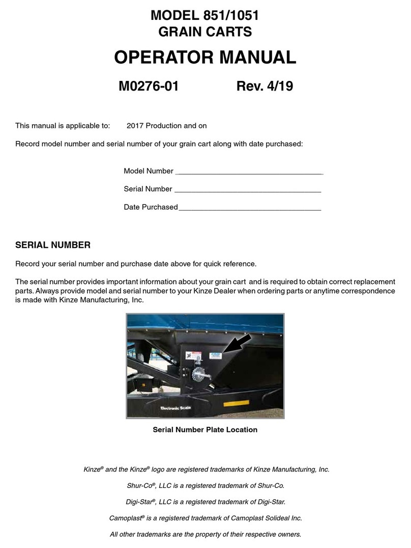
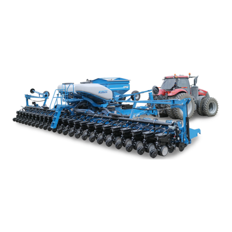
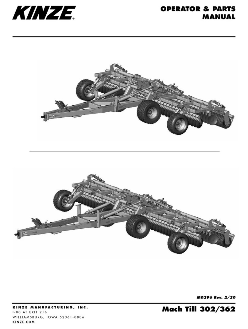
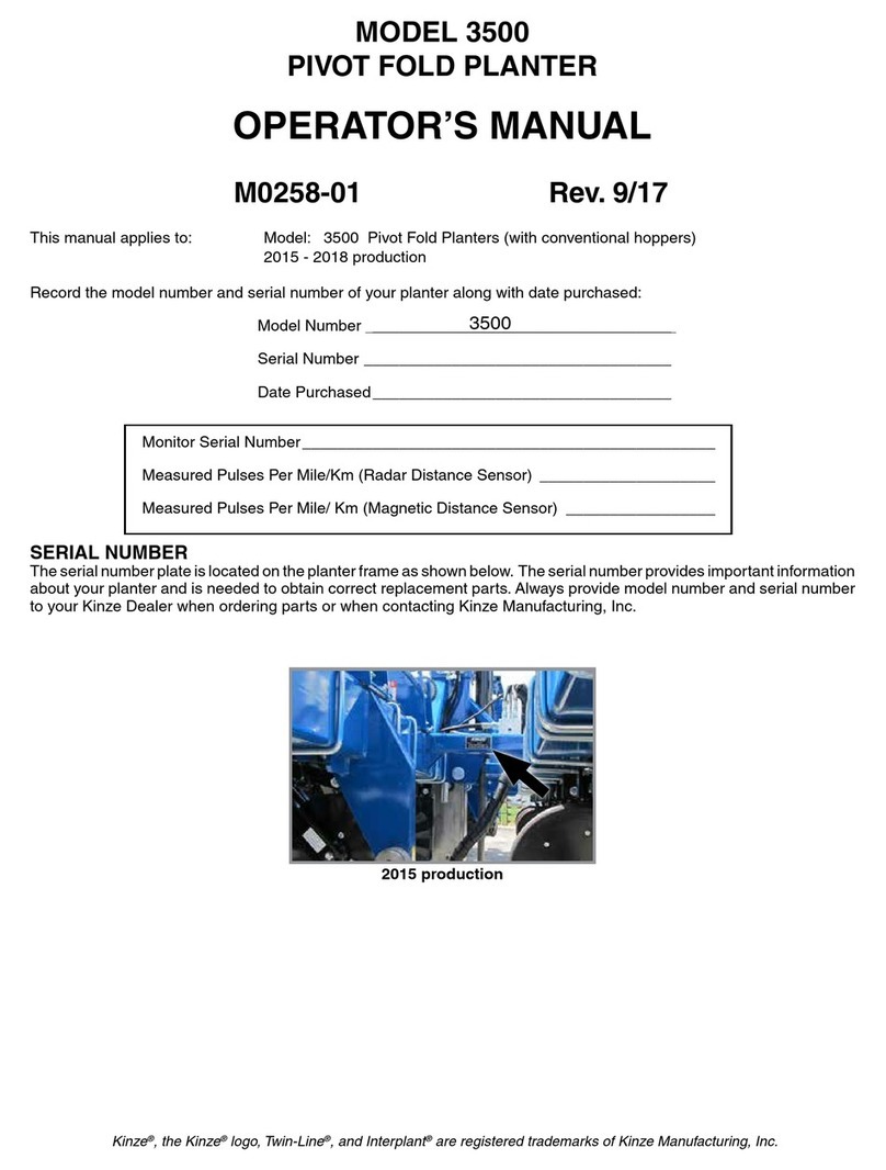
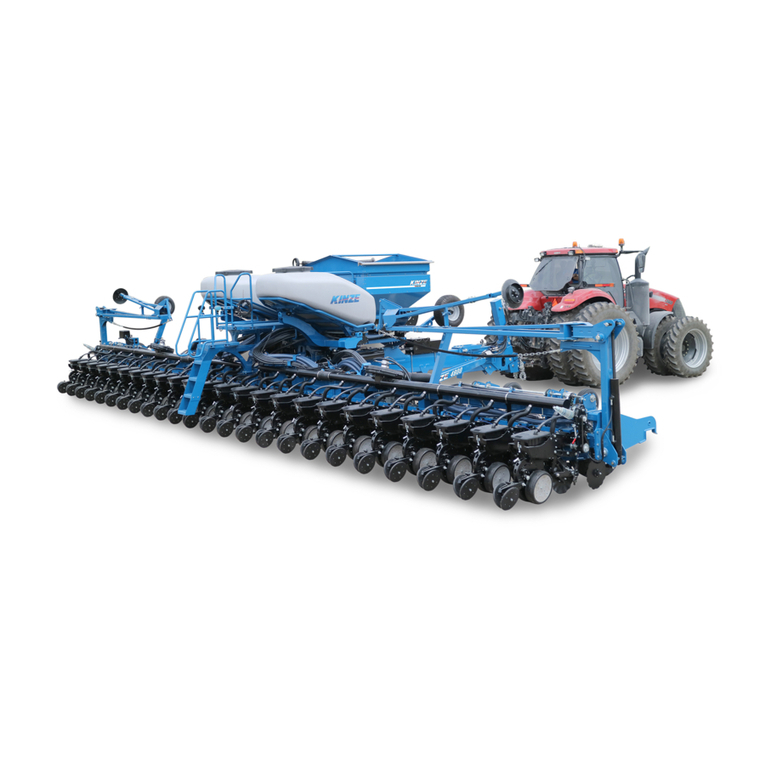
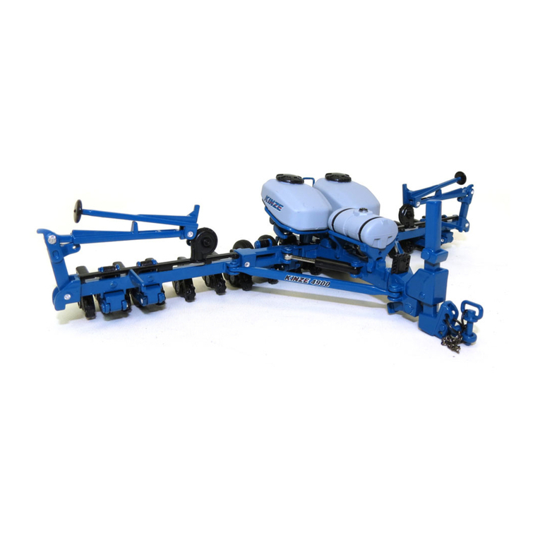
Kinze 3600 User manual

Rev.3/05
MODEL 3600
TWIN-LINE®PLANTER
OPERATOR & PARTS
MANUAL
M0167 Rev. 3/05
This manual is applicable to: Model: 3600Twin-Line®Planters
Serial Number: 613810 and on
Recordthemodelnumberandserialnumberofyour planter alongwithdatepurchased:
ModelNumber 3600
SerialNumber
DatePurchased
MonitorSerialNo.
MeasuredPulses Per Mile/Km (RadarDistanceSensor)
MeasuredPulses Per Mile/Km(Magnetic Distance Sensor)
76746-3b
KINZE®, the KINZE®logo, Twin-Line®and Interplant®are registered trademarks of KINZE Manufacturing, Inc.
SERIAL NUMBER
Theserial numberplateislocated ontheplanterframe
to be readily available. It is suggested that the serial
numberandpurchasedatealsoberecordedabove.
Theserialnumberprovidesimportantinformationabout
your planter and may be required to obtain the correct
replacementpart.Alwaysprovidethemodelnumberand
serial number to your KINZE®Dealer when ordering
parts or anytime correspondence is made with KINZE
Manufacturing,Inc.


PREDELIVERY/DELIVERY CHECKLIST
TO THE DEALER
Predelivery service includes assembly, lubrication, adjustment and test. This service helps to ensure that the planter
will be delivered to the customer ready for field use.
PREDELIVERY CHECKLIST
After the planter has been completely assembled, use the following checklist and inspect the planter. Check off each
item as it is found satisfactory or after proper adjustment is made.
Recheck to be sure row units are properly spaced and optional attachments are correctly assembled.
Thehardwarebox,containingtherowunitdrivechainsandmeterdriveclutches,hasbeenremovedfromtheseed
hopper on the L.H. side of the planter and those components have been installed. See “Row Unit Assembly And
Installation Instruction”.
Therowmarkerbladeassemblieshavebeenremovedfromtheirshippinglocationovertheplanterhitchandinstalled
on the row marker assembly at each end of the planter. See “Row Marker Adjustment” in the Machine Operation
Section of this manual.
Be sure all grease fittings are in place and lubricated.
Check planter and make sure all working parts are moving freely, bolts are tight and cotter pins are spread.
Check all drive chains for proper tension and alignment.
Checkforoil leaks and properhydraulicoperation.
Check to be sure hydraulic hoses are routed correctly to prevent damage to hoses.
Inflate tires to specified PSI air pressure. Tighten wheel lug bolts and lug nuts to specified torque.
Check to be sure all safety decals are correctly located and legible. Replace if damaged.
Check to be sure all reflective decals are correctly located and visible when the planter is in transport position.
Check to be sure SMV sign is in place.
Check to be sure safety/warning lights are installed correctly and working properly.
Paint all parts scratched in shipment or assembly.
Be sure all safety lockup devices are on the planter and correctly located.
Check seed meters on test stand to ensure proper performance.
Auxiliary safety chain is properly installed and hardware is torqued to specification.
Thisplanterhasbeenthoroughlycheckedandtothebestofmyknowledgeisreadyfordeliverytothecustomer.
(SignatureOfSet-UpPerson/DealerName/Date)
Rev. 3/05
OWNER REGISTER
Name DeliveryDate
Street Address Model No. Serial No.
City, State/Province Dealer Name
ZIP/Postal Code Dealer No.

DELIVERY CHECKLIST
Atthetimetheplanterisdelivered,thefollowingchecklististobeusedasareminderofveryimportantinformationwhich
should be conveyed to the customer. Check off each item as it is fully explained to the customer.
Advise the customer that the life expectancy of this or any other machine is dependent on regular lubrication as
directed in the Operator & Parts Manual.
Tell the customer about all applicable safety precautions.
Along with the customer, check to be sure the reflective decals and SMV sign are clearly visible with the planter in
transport position and attached to the tractor. Check to be sure safety/warning lights are in working condition. Tell
thecustomertocheckfederal,state/provincialandlocalregulationsbeforetowingortransportingonaroadorhighway.
Give the Operator & Parts Manual to the customer and explain all operating adjustments.
Readwarrantytocustomer.
CompleteWarrantyAndDeliveryReportform.
Tothe best of myknowledgethismachine has been deliveredreadyforfield use and customerhasbeenfully
informed as to proper care and operation.
(SignatureOfDeliveryPerson/DealerName/Date)
AFTER DELIVERY CHECKLIST
The following is a list of items we suggest to check during the first season of use of the equipment.
Check with the customer as to the performance of the planter.
Reviewwith the customer theimportanceof proper maintenance andadherencewith all safety precautions.
Check for parts that may need to be adjusted or replaced.
Check to be sure all safety warning signs (decals), reflective decals and SMV sign are correctly located and that
decals are legible. Replace if damaged or missing.
Checkto be suresafety/warning lights are workingproperly.
(SignatureOfFollow-UpPerson/DealerName/Date)
RETURN THIS COMPLETED FORM TO KINZE®IMMEDIATELY, along with Warranty And Delivery Report.
Retain photocopy of this form at dealership for After Delivery Check.
Tear Along Perforation
Rev.3/05

TABLE OF CONTENTS
TO THE OWNER..............................................................................................................1-1
WARRANTY ....................................................................................................................1-2
INTRODUCTION..............................................................................................................2-1
SPECIFICATIONS ...........................................................................................................3-1
SAFETY PRECAUTIONS ................................................................................................4-1
SAFETY WARNING SIGNS.............................................................................................5-1
MACHINE OPERATION
Auxiliary Hydraulic Option ............................................................................................... 6-75
Checking Granular Chemical Application Rate............................................................... 6-93
Checking Seed Population............................................................................................... 6-92
Contact Drive Wheel Spring Adjustment........................................................................... 6-3
Dry Fertilizer Attachment................................................................................................. 6-82
Electronic Seed Monitor System
KPM I ....................................................................................................................... 6-16
KPM II ...................................................................................................................... 6-22
KPM II Stack-Mode................................................................................................. 6-44
Even-Row Push Row Unit ............................................................................................... 6-74
Fertilizer Openers And Attachments............................................................................... 6-76
Field Operation.................................................................................................................6-10
Field Test.......................................................................................................................... 6-91
Field To Transport Sequence.......................................................................................... 6-10
General Planting Rate Information .................................................................................. 6-94
Half Rate (2 To 1) Drive .................................................................................................... 6-4
Hydraulic/Electric Operation.............................................................................................. 6-6
Initial Preparation Of The Planter ...................................................................................... 6-1
Leveling The Planter .......................................................................................................... 6-2
Liquid Fertilizer Attachment ............................................................................................. 6-84
Manual Safety Lockup ..................................................................................................... 6-89
Metric Conversion Table ................................................................................................. 6-91
Planting And Application Rate Charts.............................................................................. 6-95
Planting Speed ................................................................................................................. 6-91
Point Row Clutch.............................................................................................................. 6-72
Rear Trailer Hitch............................................................................................................. 6-88
Ridge Planting .................................................................................................................... 6-5
Rock Guards ................................................................................................................... 6-74
Row Marker Length Adjustment...................................................................................... 6-14
Row Marker Operation .................................................................................................... 6-13
Row Marker Safety Lockup............................................................................................. 6-89
Row Marker Speed Adjustment ...................................................................................... 6-14
Seed Rate Transmission Adjustment................................................................................ 6-4
Shear Protection ................................................................................................................ 6-6
Standard Rate Drive .......................................................................................................... 6-4
Tire Pressure ..................................................................................................................... 6-3
Tongue Safety Pin............................................................................................................ 6-90
Tractor Preparation And Hookup ...................................................................................... 6-1
Tractor Requirements ....................................................................................................... 6-1
Transport Latch Locking Pin ........................................................................................... 6-90
Transport To Field Sequence............................................................................................ 6-7
Transporting The Planter................................................................................................. 6-91
Two-Speed Point Row Clutch.......................................................................................... 6-73
Wrap Spring Wrench Operation ........................................................................................ 6-5
ROW UNIT OPERATION
Brush-Type Seed Meter .................................................................................................... 7-5
Closing Wheel Shield.......................................................................................................... 7-2
Coulter Mounted Residue Wheels ................................................................................... 7-19
Covering Discs/Single Press Wheel Adjustment .............................................................. 7-2
Drag Closing Attachment................................................................................................... 7-3
Finger Pickup Seed Meter ................................................................................................. 7-4
Frame Mounted Coulters And Attachments ................................................................... 7-12
Granular Chemical Bander Shield ................................................................................... 7-20
Granular Chemical Banding Options............................................................................... 7-20
Granular Chemical Hopper And Drive ............................................................................ 7-19
Interplant®Push Row Unit Clutch Sprocket .................................................................... 7-22
Interplant®Push Row Unit Lockups ................................................................................ 7-21
Planting Depth .................................................................................................................... 7-1
Quick Adjustable Down Force Springs ........................................................................... 7-10
Row Unit Chain Routing..................................................................................................... 7-9
Row Unit Extension Brackets............................................................................................ 7-8
Row Unit Mounted Bed Leveler ....................................................................................... 7-16
Row Unit Mounted Disc Furrower................................................................................... 7-16
Row Unit Mounted No Till Coulter ................................................................................... 7-18
Row Unit Mounted Residue Wheel.................................................................................. 7-16
Rev.7/04

Rev.3/05
TABLE OF CONTENTS
ROWUNIT OPERATION (Continued)
Seed Hopper ...................................................................................................................... 7-7
Seed Meter Drive Adjustment............................................................................................ 7-8
Seed Meter Drive Release ................................................................................................ 7-7
Spring Tooth Incorporator ............................................................................................... 7-20
“V” Closing Wheel Adjustment (Rubber And Cast Iron) ................................................... 7-1
LUBRICATION
Bushings............................................................................................................................. 8-4
Center Post ........................................................................................................................ 8-6
Drive Chains ...................................................................................................................... 8-2
Grease Fittings .................................................................................................................. 8-7
Interplant® Push Row Unit Lockups................................................................................... 8-5
Liquid Fertilizer Piston Pump Crankcase Oil Level .......................................................... 8-7
Lubrication Symbols........................................................................................................... 8-1
Point Row Clutches............................................................................................................ 8-7
Sealed Bearings ................................................................................................................. 8-1
U-Joint Slides ..................................................................................................................... 8-6
Wheel Bearings .................................................................................................................. 8-6
Wrap Spring Wrench Assembly ........................................................................................ 8-6
MAINTENANCE
15" Seed Opener Disc Blade/Bearing Assembly............................................................ 9-10
Brush-Type Seed Meter Maintenance .............................................................................. 9-5
Chain Tension Adjustment................................................................................................. 9-1
Check Valve ..................................................................................................................... 9-19
Coulter Mounted Residue Wheels................................................................................... 9-14
Drag Closing Attachment................................................................................................... 9-8
Electrical Control Console Schematic ............................................................................. 9-32
Electrical Control Console Schematic (W/Optional Two-Speed Point Row Clutches).. 9-37
Electrical Wiring Diagram For Light Package ................................................................. 9-31
Electrical Wiring Harness Schematic (On Tractor)........................................................ 9-33
Electrical Wiring Harness Schematic (On Planter) ........................................................ 9-34
Finger Pickup Seed Meter Cleaning.................................................................................. 9-3
Finger Pickup Seed Meter Inspection/Adjustment ........................................................... 9-2
Flow Control Valve Inspection ......................................................................................... 9-20
Frame Mounted Coulters And Attachments ................................................................... 9-11
Gauge Wheel Adjustment .................................................................................................. 9-8
Gauge Wheel Arm Bushing And/Or Seal Replacement ................................................... 9-9
Gauge Wheel Arm Pivot Spindle Replacement................................................................. 9-9
Granular Chemical Attachment ....................................................................................... 9-15
Hydraulic System Schematic .......................................................................................... 9-38
Mounting Bolts And Hardware ........................................................................................... 9-1
Piston Pump Storage ....................................................................................................... 9-28
Point Row Clutch Inspection............................................................................................ 9-17
Preparation For Storage .................................................................................................. 9-30
Pressure Relief Valve Inspection .................................................................................... 9-20
Relief Valve (Located On Hitch)...................................................................................... 9-19
Row Marker Bearing Lubrication Or Replacement ........................................................ 9-25
Row Marker Transport Stand Adjustment ...................................................................... 9-25
Row Unit Mounted Bed Leveler ....................................................................................... 9-13
Row Unit Mounted Disc Furrower................................................................................... 9-12
Row Unit Mounted No Till Coulter ................................................................................... 9-14
Row Unit Mounted Residue Wheel.................................................................................. 9-13
Seed Tube Guard/Inner Scraper .................................................................................... 9-11
Solenoid Valve Inspection................................................................................................ 9-19
Spring Tooth Incorporator ............................................................................................... 9-15
Troubleshooting
Brush-Type Seed Meter Troubleshooting ................................................................... 9-7
Closing Wheel Troubleshooting.................................................................................... 9-8
Finger Pickup Seed Meter Troubleshooting ................................................................ 9-4
KPM I/ KPM II/KPM II Stack-Mode Electronic Seed Monitor Troubleshooting ......... 9-16
Lift Circuit Troubleshooting ......................................................................................... 9-20
Point Row Clutch Troubleshooting ............................................................................. 9-18
Rotation Cylinder Circuit Troubleshooting ................................................................. 9-23
Row Marker Operation Troubleshooting ................................................................... 9-24
Solenoid Valve Troubleshooting ................................................................................. 9-19
Tongue Cylinder Circuit Troubleshooting .................................................................. 9-22
Wing Lock Cylinder Circuit Troubleshooting.............................................................. 9-23
Piston Pump Troubleshooting .................................................................................... 9-29
Torque Values Chart.......................................................................................................... 9-1
Two-Speed Point Row Clutch.......................................................................................... 9-19
Wear Pad Replacement And Adjustment ........................................................................ 9-26
Wheel Bearing Lubrication Or Replacement................................................................... 9-26
PARTS LIST INDEX......................................................................................................... P1
PARTS SECTION NUMERICAL INDEX ............................................................................ a

1-1 Rev.3/05
TO THE OWNER
KINZEManufacturing,Inc.wouldlike tothankyouforyourpatronage.Weappreciateyourconfidence inKINZE®farm
machinery. Your KINZE®planter has been carefully designed to provide dependable operation in return for your
investment.
This manual has been prepared to aid you in the operation and maintenance of the planter. It should be
considered a permanent part of the machine and remain with the machine when you sell it.
ItistheresponsibilityoftheusertoreadandunderstandtheOperator&PartsManualinregardstosafety,operation,
lubricationandmaintenancebeforeoperationofthisequipment.It is the user’s responsibility to inspect and service
the machine routinely as directed in the Operator & Parts Manual. We have attempted to cover all areas of safety,
operation, lubrication and maintenance; however, there may be times when special care must be taken to fit your
conditions.
Throughoutthismanualthesymbol and/orthewordsNOTE,IMPORTANT,CAUTION,WARNINGorDANGER
are used to call your attention to important information. The definition of each of these terms follows:
NOTE: Indicates a special point of information or addresses a machine adjustment.
IMPORTANT: Indicates information which, if not heeded, could result in damage to the machine.
CAUTION: Indicates a potentially hazardous situation which, if not avoided, may result in minor or
moderatepersonalinjury.
WARNING: Indicates a potentially hazardous situation which, if not avoided, could result in death or
seriouspersonal injury.
DANGER: Indicates an imminently hazardous situation which, if not avoided, will result in death or
seriouspersonal injury.
WARNING: Somephotos in this manual mayshow safety covers, shields orlockup devices removed
forvisualclarity.NEVEROPERATEthemachinewithoutallsafetycovers,shieldsandlockupsinplace.
NOTE: Some photos in this manual may have been taken of prototype machines. Production machines may vary in
appearance.
NOTE: Somephotosandillustrationsinthismanualshowoptionalattachmentsinstalled.ContactyourKINZE®Dealer
for purchase of optional attachments.

WARRANTY
TheKINZE®LimitedWarrantyforyournewmachineisstatedonthebackoftheretailpurchaser’scopyoftheWarranty
And Delivery Report form. Additional copies of the Limited Warranty can be obtained through your KINZE®Dealer.
Warranty,within the warranty period, isprovidedas part ofKINZE’ssupport program forregisteredKINZE®products
whichhave been operated andmaintainedasdescribedinthismanual. Evidence of equipmentabuseormodification
beyond original factory specifications will void the warranty. Normal maintenance, service and repair is not covered
by KINZE®warranty.
ToregisteryourKINZE®productforwarranty,aWarrantyAndDeliveryReportformmustbecompletedbytheKINZE®
Dealer and signed by the retail purchaser, with copies to the Dealer, to the retail purchaser and to KINZE
Manufacturing,Inc. Registration mustbecompleted and senttoKINZE Manufacturing, Inc.within 30 daysofdelivery
oftheKINZE®producttotheretailpurchaser.KINZEManufacturing,Inc.reservestherighttorefusewarrantyonserial
numbered products which have not been properly registered.
If service or replacement of failed parts which are covered by the Limited Warranty are required, it is the user’s
responsibilityto deliver themachinealong with theretailpurchaser’s copy oftheWarranty And DeliveryReportto the
KINZE®Dealer for service. KINZE®warranty does not include cost of travel time, mileage, hauling or labor. Any prior
arrangementmadebetweentheDealerandtheretailpurchaserinwhichtheDealeragreestoabsorballorpartofthis
expense should be considered a courtesy to the retail purchaser.
KINZE®warranty does not include cost of travel time, mileage, hauling or labor.
1-2 Rev.10/03

The Model 3600 Twin-Line®Planter is available in
various configurations and row spacings. Optional
Interplant®row spacing is obtainable with the addition
of push row units.
TheModel3600Twin-Line®Planterpermitsinstallation
of liquid or dry fertilizer application equipment and
various row unit attachments.
GENERAL INFORMATION
Theinformationused in this manualwascurrentat the
time of printing. However, due to KINZE’s continual
attempts to improve its product, production changes
may cause your machine to appear slightly different in
detail. KINZE Manufacturing, Inc. reserves the right to
change specifications or design without notice and
without incurring obligation to install the same on
machines previously manufactured.
Righthand(R.H.)andlefthand(L.H.),asusedthroughout
thismanual,aredeterminedbyfacinginthedirection the
machinewill travel wheninuseunlessotherwisestated.
2-1 Rev.3/05
D020501123a
INTRODUCTION
D061901101
D062991118
ShownWithOptionalInterplant®Package
Shown With Optional Liquid Fertilizer Package
Shown With OptionalDry FertilizerPackage

2-2 6/99
INTRODUCTION

SPECIFICATIONS
TYPE - Pull Type (Hydraulically rotates endwise to transport)
PLANTING UNIT TYPES - Push and Pull Row Units
ROWSPACING Standard Interplant®Package
8 Row Wide - 36" or 38" Rows 15 - 18" or 19" Rows
12RowNarrow-30"Rows 23 - 15" Rows or 24 - 15" Rows
12 Row Wide - 36" or 38" Rows 23 - 18" or 19" Rows
16RowNarrow-30"Rows 31 - 15" Rows or 32 - 15" Rows
DRIVE SYSTEM - Spring-loaded contact drive system
- 7.50" x 20" 8 ply rib implement wing tire - two on 8 and 12 row; four on 16 row
- 4.80" x 8" 6 ply contact drive tire - two on 8 and 12 row; four on 16 row
-No.40rollerchainandspring-loadedidlers
- Point row clutches standard on 12 and 16 row sizes and optional on 8 row size
- 7/8" hex drill and drive shafts and end mounted seed transmissions
TRANSPORTTIRES - Equipped with four 255 - 70R 22.5" radial load range H tubeless rib implement tires
-Adjustableheightwheels for ridge planting
TYPE LIFT - Master/slave hydraulics
- 8 and 12 row - 2 center lift (master) cylinders, 1 cylinder per wing wheel module (2 slave)
- 16 row - 2 center lift (master) cylinders, 2 cylinders per wing wheel module (4 slave)
MARKERS-Independently controlled. Two-fold,lowprofilewithdepthband on markerdiscblade
MACHINEOPTIONS
• Electronic Seed Monitors
KPM I
KPM II With Magnetic Distance Sensor Or Radar Distance Sensor
KPM II Stack-Mode With Magnetic Distance Sensor Or Radar Distance Sensor
• Point Row Clutch Package - Allows half width planting. (Std. 12/16 row, Optional 8 row)
•Two-Speed PointRow Clutch Package- Allows half width plantingand reduced rateplanting
(AvailablethroughKINZE®RepairParts)
• Interplant®Package
• Even-Row Push Row Unit Package
• Liquid Fertilizer Package
• Dry Fertilizer Package
• Half Rate (2 To 1) Drive Reduction Package
•Rear Trailer Hitch
• Piston Pump Mount And Drive Package
•Rock GuardPackage For TransportWheel Arm
ROWUNITOPTIONS/ATTACHMENTS
• Finger Pickup Or Brush-Type Seed Meters
•Closing Wheel Options
Rubber“V”ClosingWheels
CastIron “V” Closing Wheels
CoveringDiscs/SinglePressWheel
DragClosingAttachment
•GranularChemicalApplication
•Hopper PanelExtension Package
•SpringToothIncorporator
• Row Unit Extension Brackets
• Row Unit Mounted No Till Coulter
•RowUnitMountedDiscFurrowers
•Row Unit Mounted BedLeveler
•RowUnitMountedResidueWheel
•CoulterMountedResidueWheels
• Frame Mounted Coulter - STYLE A & STYLE B
• Disc Furrowers For STYLE A Frame Mounted Coulter
•Residue WheelsFor STYLE BFrame MountedCoulter
3-1 Rev.3/05

Dimensions/Operating
PLANTER SIZE 8 Row 36"/38" 12 Row 30" 12 Row 36"/38" 16 Row 30"
WIDTH 26'6" 31'2" 37'2" 41'2"
LENGTH - “Y” Hitch 19' 0" 21' 0" 22' 0" 24' 0"
LENGTH - “T” Hitch 17' 0" 19' 0" 20' 0" 22' 0"
Dimensions/Transport
PLANTER SIZE 8 Row 36"/38" 12 Row 30" 12 Row 36"/38" 16 Row 30"
WIDTH 13' 4" 11' 2" 13' 4" 11' 2"
Std., fertilizer or push row units
WIDTH
Push row unit with no till coulters 13' 4" 11' 4" 13' 4" 11' 4"
Push row unit with no till coulters
and coulter mounted
residue wheels 13' 4" 11' 8" 13' 4" 11' 8"
LENGTH 30'6" 36'10" 43'10" 46'10"
HEIGHT 10' 8" 10' 8" 10' 8" 11' 0"
NOTE: L.H. transport wheel and axle stub assembly is removable for truck transport at 10' 3" width on wide row
machines and 8' 6" on narrow row machines.
PLANTER SIZE 8 Row 36"/38" 12 Row 30" 12 Row 36"/38" 16 Row 30"
*WEIGHT 11,678lbs. 12,816lbs. 13,558lbs. 15,778lbs.
* BaseMachineweightsincludeplanterframe,rowmarkers,drivecomponents,tiresandwheels,hydrauliccylinders
andhoses,12VDCcontrolconsole,KINZE®pullrowunits(closingwheelarmslessclosingwheels),seedhopperand
lid,dualquick-adjustabledownforcesprings,transportsafetychainandpointrowclutches(12rowandlargersizes).
3-2 Rev.7/04
SPECIFICATIONS

Safe and careful operation of the tractor and planter
atalltimeswillcontributesignificantlytotheprevention
of accidents.
Sincealargeportionoffarmaccidentsoccurasaresult
of fatigue or carelessness, safety practices should
be of utmost concern. Read and understand the
instructionsprovidedinthismanualandonthewarning
signs. Review these instructions frequently! Listed
belowareothersafetysuggestionsthatshouldbecome
common practice.
Never allow the planter to be operated by
anyonewhoisunfamiliarwiththeoperation
of all functions of the unit. All operators
should read and thoroughly understand
the instructions given in this manual prior
to moving the unit.
Never permit any persons other than the
operator to ride on the tractor.
Never ride on the planter or allow others to
do so.
Always make sure there are no persons
neartheplanterwhenrowmarkerassemblies
areinoperationorwhenrotatingtheplanter.
Alwayskeephands,feet andclothingaway
from moving parts. Do not wear loose-
fitting clothing which may catch in moving
parts.
Always wear protective clothing,
substantialshoesandsuitablehearingand
eye sight protectors applicable for the
situation.
Do not allow anyone to stand between the
tongue or hitch and the towing vehicle
when backing up to the planter.
Be aware of bystanders, particularly
children! Alwayslookaroundtomakesure
it is safe to start the engine of the towing
vehicle or move the planter. This is
particularly important with higher noise
levels and quiet cabs, as you may not hear
people shouting.
4-1 Rev.3/05
SAFETY PRECAUTIONS
Use a tractor equipped with a roll-over-
protective-systemandfastenyourseatbelt
prior to starting the engine.
Beforeoperatingtheplanterforthefirsttime
andperiodicallythereafter,checktobesure
the lug nuts on the transport wheels are
tight. This is especially important if the
planter is to be transported for a long
distance.
Never work under the planter while in raised
position without using manual safety lockup
device.
Installsafetylockupdevicesonrowmarkers
priorto transportingthe planterorworking
around the unit.
Watch for obstructions such as wires, tree
limbs, etc., when folding row markers.
To avoid serious injury or death, care must
betakenwhenoperatingrowmarkersaround
overheadpowerlines.
Onmachineswheretheoutertransportwheel
on the left side of the planter is bolt-on to
allow legal width truck shipment, always
installoutertransportwheelassemblyprior
to unloading. DO NOT REMOVE THIS
ASSEMBLY AFTER PLANTER IS
ASSEMBLEDFORUSE.DONOTfoldplanter
or tow planter while the outer transport
wheel is removed. Tipping may occur
becauseofnarrowwheelbase.
This planter is designed to be DRIVEN BY
GROUNDTIRESONLY.Theuseofhydraulic,
electric or PTO drives may create serious
safetyhazardstoyouandthepeoplenearby.
Ifyouinstallsuchdrivesyoumustfollowall
appropriatesafetystandardsandpractices
to protect you and others near this planter
from injury.
D060299127a

Always install tongue safety pin, manual
safety lockup device and transport latch
lockingpinbeforetransportingplanter.
D060299102
Tongue Safety Pin
D060299107
ManualSafetyLockupdevice
D060299106
Transport Latch Locking Pin 4-2 Rev.3/05
SAFETY PRECAUTIONS
This machine has been designed and built
with your safety in mind. Do not make any
alterations or changes to this machine.
Anyalterationtothedesignorconstruction
may create safety hazards.
Alwaysfollow federal, state/provincial and
local regulations when towing farm
equipment on a public highway. Only a
safetychain(notanelasticornylon/plastic
tow strap) should be used to retain the
connection between the towing and towed
machines in the event of separation of the
primaryattachingsystem.
Check to be sure all safety/warning lights
are working properly before transporting
the machine on public roads.
Avoid transporting planter with hoppers
loaded whenever possible. When it is
necessary to transport the planter with the
hoppers loaded, the added weight should
be distributed evenly on the planter frame
before rotating the planter.
Limit towing speed to 15 MPH. Tow only
with farm tractor of a minimum 90 HP.
Always make sure safety/warning lights,
reflective decals and SMV sign are in place
andvisiblepriortotransportingthemachine
on public roads. In this regard, check
federal, state/provincial and local
regulations.
Allow for unit length when making turns.
Always drive at a safe speed relative to
local conditions and ensure your speed is
low enough for an emergency stop to be
safeandsecure. Keepspeedtoaminimum.
Reduce speed prior to turns to avoid the
risk of overturning.

4-3 Rev.3/05
Always keep the tractor in gear to provide
engine braking when going downhill. Do
not coast.
Avoidsuddenuphillturnsonsteepslopes.
Be a safe and courteous driver. Always
yield to oncoming traffic in all situations,
includingnarrowbridges,intersections,etc.
Rim and tire servicing can be dangerous.
Explosiveseparationofatireand rimparts
can cause serious injury or death.
Agricultural chemicals can be dangerous.
Improper selection or use can seriously
injure persons, animals, plants, soil and
other property. BE SAFE: Select the right
chemical for the job. Handle it with care.
Follow the instructions on the container
labeland of the equipment manufacturer.
Store the planter in an area away from
humanactivity. DONOT permitchildren to
play on or around the stored unit.
Makesuretheparkedmachineisonahard,
levelsurface. Wheelchocksmaybeneeded
to prevent unit from rolling.
Good maintenance is your responsibility.
Poormaintenanceisaninvitationtotrouble.
SAFETY PRECAUTIONS

4-4 6/99
SAFETY PRECAUTIONS

5-1 Rev.3/05
SAFETY WARNING SIGNS
The“WARNING” signs illustratedonthese pages areplacedon the machinetowarn of hazards.Thewarnings found
on these signs are for your personal safety and the safety of those around you. OBSERVE THESE WARNINGS!
•Keep these signs clean so they can be readily observed. Wash with soap and water or cleaning solution
as required.
•Replace “WARNING” signs should they become damaged, painted over or if they are missing.
•Check reflective decals and SMV sign periodically. Replace if they show loss of any of their reflective
property.
•When replacing decals, clean the machine surface thoroughly using soap and water or cleaning
solution to remove all dirt and grease.
NOTE: The production date of the machine will determine style and locations of SMV sign, reflectors and/or
reflectivedecalsandsafety/warninglightstoconformtoANSI/ASAES279.12DEC02andANSI/ASAES276.5FEB
03.
82079-2a
Part No. G7100-117 (Qty. 1)Part No. G7100-02 (Qty. 1)
Part No. G7100-63 (Qty. 1)
Part No. G7100-68 (Qty. 1)

SAFETY WARNING SIGNS
5-2 Rev.3/05
PartNo. G7100-83(Qty. 2 -One PerMarker)
Part No. G7100-42 (Qty. 4 - Two Per Marker)
D060299127a
76746-3b
Part No. G7100-75
(Qty. 4 - Front And Rear/Left And Right)
PartNo.G7100-302(Qty.1)
D092702101a

SAFETY WARNING SIGNS
5-3 Rev.7/04
D08169904
D060299104
Part No. G7100-90 (Qty. 1)
Part No. G7100-46 (Qty. 1)
Part No. G7100-200 (Qty. 2 - Front And Rear)
Part No. G7100-68 (Qty. 2 - Front And Rear)

SAFETY WARNING SIGNS
5-4 Rev. 5/01
D06189903
Part No. G7200-04 Amber Reflector
(Qty. 2 - Located At Each End Of Front Axle)
(If Applicable)
Part No. G7200-03 Red Reflector
(Qty. 2 - Located On Outside Two Transport
Tire Scrapers) (If Applicable)
Part No. G7200-03 Red Reflector (Qty. 2)
(If Applicable)
D060299204
Part No. G7100-219 (Qty. 4 - One On Each
Transport Wheel)
D060299108
Part No. G7100-215 (Qty. 1 - Located On Rear
Side Of Stub Axle)
7100-215
DO NOT REMOVE THIS ASSEMBLY
AFTER PLANTER IS ASSEMBLED
FOR USE. REMOVAL OF THIS
WHEEL AND AXLE ASSEMBLY CAN
CAUSE THE MACHINE TO BECOME
UNSTABLE AND TIP OVER CAUSING
DAMAGE OR SERIOUS INJURY.
Other manuals for 3600
1
Table of contents
Other Kinze Farm Equipment manuals