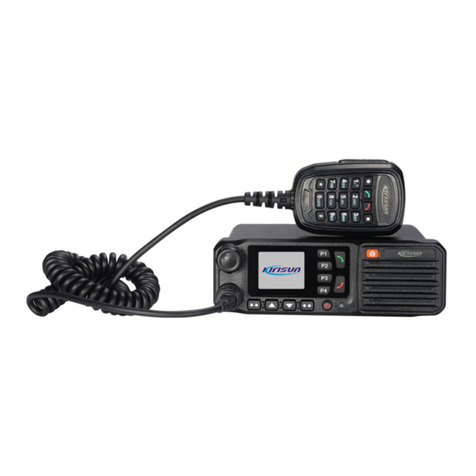
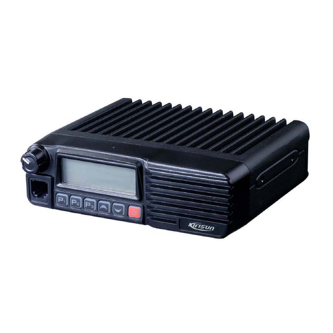
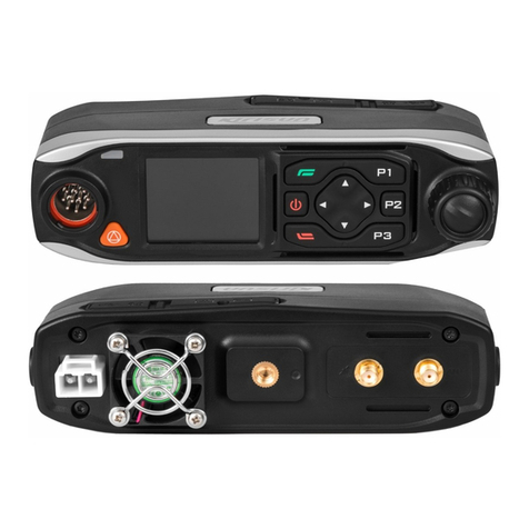
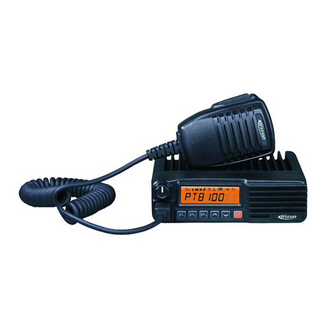
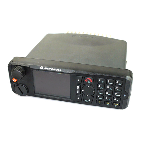
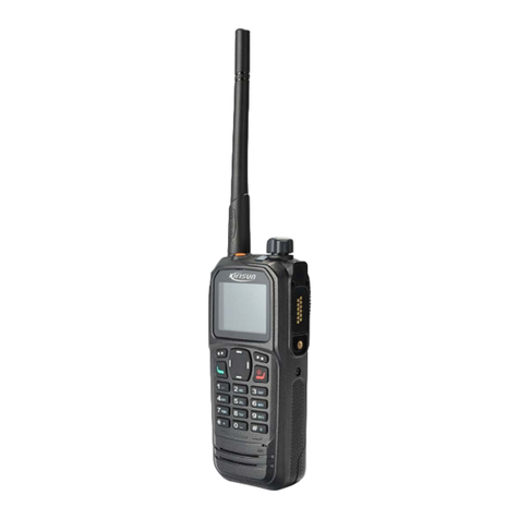
Kirisun TM840 User manual

TM840 Service Manual
I

TM840 Service Manual
Contents
CONTENTS .............................................................................................................................................................................II
CHAPTER 1. FOREWORD ........................................................................................................................................................1
1.1. SCOPE OF MANUAL.............................................................................................................................................................1
1.2. SAFETY PRECAUTIONS..........................................................................................................................................................1
CHAPTER 2. PRODUCT CONTROLS .......................................................................................................................................... 2
2.1 PRODUCT CONTROLS...........................................................................................................................................................2
2.2 LED INDICATOR ..................................................................................................................................................................3
CHAPTER 3. CIRCUIT DESCRIPTION......................................................................................................................................... 3
3.1 RF CIRCUIT .......................................................................................................................................................................3
3.1.1 TRANSMITTER CIRCUIT ........................................................................................................................................................4
3.1.2 RECEIVER CIRCUIT ..............................................................................................................................................................5
3.1.3 FREQUENCY GENERATION UNIT(FGU) ...................................................................................................................................6
3.1.4 GPS CIRCUIT.....................................................................................................................................................................7
3.2 BASEBAND SECTION ............................................................................................................................................................8
3.2.1BASEBAND SYSTEM .............................................................................................................................................................8
3.2.2 POWER SECTION ..............................................................................................................................................................10
3.2.3 AUDIO PROCESSING ..........................................................................................................................................................11
3.2.4 CONTROL PANEL ..............................................................................................................................................................12
CHAPTER 4. PC PROGRAMMING MODE ............................................................................................................................... 13
4.1 GENERAL FUNCTIONS ........................................................................................................................................................13
4.2 PC PROGRAMMING ..........................................................................................................................................................14
4.2.1 PARAMETERS SETTING STEPS...............................................................................................................................................14
4.2.2 PROGRAMMING INSTALLATION STEPS....................................................................................................................................14
CHAPTER 5. ASSEMBLE AND DISASSEMBLE INSTRUCTIONS............................................................................................... 18
5.1 REMOVING THE FRONT PANEL FROM TRANSCEIVER ..................................................................................................................18
5.2 DISASSEMBLE OF MAIN BODY ..............................................................................................................................................19
5.3 REMOVE RF PCBA ...........................................................................................................................................................19
5.4 DISASSEMBLE FRONT PANEL ................................................................................................................................................20
5.5 REMOVE PCBA FROM FRONT PANEL.....................................................................................................................................21
5.6 EXPLODE VIEW.................................................................................................................................................................23
CHAPTER 6. ADJUSTMENT.................................................................................................................................................... 27
6.1 THE REQUIRED TOOLS .......................................................................................................................................................27
6.2 FREQUENCY INSTRUCTION ..................................................................................................................................................27
6.2.1 INTRODUCTION TO TX MODULATION SECTION .......................................................................................................................29
6.2.2 INTRODUCTION TO RECEIVE SECTION....................................................................................................................................31
CHAPTER 7. MAIN TECHNICAL FUNCTIONS AND SPECIFICATIONS ........................................................................................ 33
CHAPTER 8. MAINTENANCE AND TEST EQUIPMENTS ........................................................................................................... 36
CHAPTER 9. COMMON FAULT PHENOMENON AND ELIMINATION METHOD ........................................................................ 37
II

TM840 Service Manual
APPENDIX SPARE PART LIST AND SCHEMATIC DIAGRAM ...................................................................................................... 38
TABLE1400-470MHZ PARTS LIST(ELECTRICS SECTION).............................................................................................................38
TABLE2136-174MHZ PARTS LIST(ELECTRICS SECTION) ..................................................................................................................47
TABLE3PARTS LIST(STRUCTURE SECTION)................................................................................................................................55
FIGURE1TM840 400-470MHZ MAINBOARD TOP SIDE PCB VIEW .................................................................................................57
FIGURE2TM840 400-470MHZ MAINBOARD BOTTOM SIDE PCB VIEW ...........................................................................................58
FIGURE3TM840 400-470MHZ KEYPAD BOARD BOTTOM SIDE PCB VIEW........................................................................................59
FIGURE4TM840 400-470MHZ KEYPAD BOARD TOP SIDE PCB VIEW ..............................................................................................60
FIGURE5TM840 400-470MHZ MAINBOARD SCHEMATIC DIAGRAM................................................................................................61
FIGURE6TM840 400-470MHZ KEYPAD BOARD SCHEMATIC DIAGRAM ............................................................................................77
FIGURE7TM840 136-174MHZ MAINBOARD TOP SIDE PCB VIEW .................................................................................................79
FIGURE8TM840 136-174MHZ MAIN BOARD BOTTOM SIDE PCB VIEW..........................................................................................80
FIGURE9. TM840 136-174MHZ KEYPAD BOARD BOTTOM SIDE PCB VIEW.......................................................................................81
FIGURE10 TM840 136-174MHZ KEYPAD BOARD TOP SIDE PCB VIEW ............................................................................................82
FIGURE11 TM840 136-174MHZ MAINBOARD SCHEMATIC DIAGRAM..............................................................................................83
FIGURE 12 TM840 136-174MHZ KEYPAD BOARD SCHEMATIC DIAGRAM .........................................................................................99
III

TM840 Service Manual
Chapter 1. Foreword
1.1. Scope of Manual
This manual is suitable for KIRISUN DMR digital mobile radio maintenance and repair. This manual is intended for use by
trained engineers and professional technicians for the maintenance and repair of TM840 digital mobile radio. Dada changes
in this manual may occur with the improvement of technology. To get the latest technology information, please contact us or
your local distributors.
Before repairing the radio, please read this manual.
1.2. Safety Precautions
Electromagnetic radiation
Radios generate and radiate electromagnetic energy, the security design of Kirisun radios’ electromagnetic radiation on
human meets national and international standards. To ensure the best communication and human security, please keep the
radio vertical to the ground, and keep the microphone 2-5 centimeters from the mouth.
Electromagnetic interference
To avoid electromagnetic interference, please turn off the radio in the place explicitly indicating the radio should be turned off,
for example, hospitals, health centers, airports, etc.
Explosive and harmful gases
In areas with explosive and harmful gases, such as the lower deck of the hull, fuel or chemical storage facilities,area where
the air contains chemicals or particles, dust or metal dust, it is better to turn off radios.
When close to the blasting area, electric blasting detonators, please turn off radios.
Replacing or recharging the batteries in potentially explosive atmospheres is prohibited.
Antenna damage
When the antenna is damaged, it is better not to use the radio. Damaged antenna could cause mild burns when contacting
with human skin.
Replacement parts
When replacing any replacement part, please be aware of the model. Do not arbitrarily replace the component that does not
match with the radio.
1

TM840 Service Manual
Chapter 2. Product Controls
2.1 Product Controls
No. Part Name No Part Name No Part Name
1 Volume Knob 8 LED Indicator 15 Programming Keys(P1-P4)
2 Microphone/Programming
Connector 9 Speaker 16 LCD Display
3 Menu/Confirm 10 Mic 17 Antenna Connetor
4 Up Key 11 PTT Key 18 Power Port
5 Down Key 12 Emergency Key 19 GPS Antenna Connector
6 Return Key 13 Hang-up Key 20 26 Pin Data Connector
7 Power On/Off 14 Dial Key
2

TM840 Service Manual
2.2 LED Indicator
LED Indicator Radio Work Status
Red LED lights on Radio is transmitting.
Green LED lights on
Radio is receiving (voice, short message, or data) or there is an activity on
the channel.
Orange LED lights on
The radio is in the call hang time period, you can press PTT to talk back
while the orange LED lights on.
Orange LED flashes
Radio is in emergency status; or there is a missed call / incoming call alert;
or the radio is scanning.
Chapter 3. Circuit Description
3.1 RF Circuit
Figure 0-1 RF schematic
3

TM840 Service Manual
3.1.1 Transmitter Circuit
Figure 3-2 Transmitter Circuit Schematic
Transmitter circuit is composed of the following three parts:
RF Power Amplifier Circuit
The TX VCO generates a carrier signal, then it will be modulated and amplified before it goes into transmitter circuit. The
signal will pass through a Π type attenuator, and it is a process which allows the interstage isolation between the RF power
amplifier circuit and the TX VCO. The signal enters a pre-driver amplifier(U42) for the first amplification. Then the signal will
go to next driver amplifier(U51) to obtain further amplification, which will provide adequate power for the final stage amplifier
module(U100) to finish the final power amplification. After multi-stage amplification, the transmitter signal will pass through
the TX/RX switch, then enter the Low Pass Filter.
Low Pass Filter Circuit
The low pass filter is a high order low pass filter which can suppress harmonics. The filter is composed of lumped parameter
inductors and capacitors. Via this filter, the capability of attenuating, the spurious signal and harmonics can be increased
when the in-band ripple conditions are satisfied.
Auto Power Control Circuit( APC ,including the temperature detection and VSWR stationary wave detection
circuit )
When radio is transmitting, the power orientation coupler will detect forward and reverse output power, which will pass
through wave detecting diode for wave detecting and sampling. The sampled RF signal will pass through an attenuator, to
the PA power controller. The output voltage will be compared(IC1-A) firstly, the compared voltage will be compared again
with the pre-set voltage(IC3-A), the output voltage will be sent to PA power controller(IC2), then compared with the APC
reference voltage and sample signal for another comparison. The voltage will be output by the power controller and the
controller will adjust the grid voltage in the RF module to achieve VSWR stationary wave detecting and power control. In the
meantime, it will judge the VSWR base one the voltage and software pre-set conditions, and protect the power amplification
circuit by controlling theAPC voltage. The APC voltage output by DAC will pass through a temperature-compensation circuit,
which allows compensating the power fluctuation that is caused by temperature difference. Then the temperature
protection circuit will amplify the voltage division network which is composed of thermistors, after an A/D conversion, it will be
4

TM840 Service Manual
provided to OMAP. OMAP will combine the VSWR rate to define the APC value to achieve the thermal protection.
3.1.2 Receiver Circuit
Figure 0-2 Receiver Circuit Schematic
The receiver circuit includes RF band pass filter, low-noise amplifier, mixer, IF filter, IF amplifier and IF processor.
The signal received from the antenna will pass the front end LPF and Tx-Rx switch controller, then it will enter the RF
electronic tuning band pass filter for frequency selecting.After that, it will be amplified by the low noise amplifier, then sent to
mix up with local oscillator signal which is provided by the first stage mixer IC3003 and VCO to achieve frequency conversion.
The first IF signal(UHF:73.35MHz,VHF:51.65MHz) output by the mixer will pass the IF filter to achieve channel selection.
Then it goes to Q18/19 for IF amplification, after that, the signal will be sent toAD9864 for second mix up andADC sampling.
After the processing, the unmodulated I/Q digital signal will be output to DSP for FM/4FSK modulation, and after voice data
uncompressing, the signal will be sent into the audio codec chip for D/A conversion. Finally, the signal passes the audio
amplifier to speaker, then sent out.
The IF signal (UHF:73.35MHz,VHF:51.65MHz)output by IF amplifier will enter the AD9864 via pin 47 of U4000 for second
frequency mix up andADC sampling, then output the unmodulated I/Q digital signal to DSP for FM/4FSK modulation.Please
refer to figure 3-4.
The reference frequency of AD9864 is 19.2MHz. The second local oscillator VCO is composed of external oscillator tube,
varactor and some other components. The local oscillator VCO provides a local oscillator signal(UHF:71.1MHZ,VHF:
49.4MHz).And the external LC syntony circuit generates aAD9864 clock frequency, which is 18MHz.
5

TM840 Service Manual
Figure 0-3 IF Processing Circuit
3.1.3 Frequency Generation Unit(FGU)
Figure 3.5 Frequency Generation Unit Diagram
Frequency generation unit(FGU) is composed of VCO and PLL. It is the core module of the TX-RX system. When
transmitting, it provides accurate carrier frequency, while receiving, it provides stable local oscillator signal. It has direct
influence on system performance.
(1)Working Principle of PLL
Benchmark crystal generates a 12.8MHz frequency, then it goes into frequency divider of the PLL chip to create a reference
6

TM840 Service Manual
frequency(i.e step frequency f1). The frequency generated by VCO will be harmonics suppress processed twice. Then it
enters the frequency divider of the PLL chip to create frequency f2. F2 will be compared with f1 in phase detector (PD) ,
which will generate a continuous pulse current. When the pulse current passes through the loop filter for RC integration, then
it is converted to CV voltage. The CV voltage will be sent to the varactor of VCO to adjusts and control the output frequency,
till the CV becomes constant. Then the PLL will be locked, the stable frequency output by VCO will go to the TX-RX channel
before passing through two buffet amplifiers.
(2)Working Principle of VCO
VCO employs oscillation mode three point capacitance. It can change the control voltage(i.e CV voltage) of varactor to
obtain different output frequencies. Rx VCO, which provides local oscillator signal, is composed by oscillation circuit and
Q24/Q29, while TX VCO is composed of oscillation circuit and Q27/Q28, and it provides transmitting signal carrier.
Two- Point Modulation
To obtain better modulation accuracy and 4FSK bit error rate when transmitting, two-point modulation is employed. MOD1
and MOD2 send the modulated signal to PLL reference crystal oscillator and VCO modulation end respectively., and to
modulate Tx benchmark crystal oscillator and VCO respectively.
3.1.4 GPS Circuit
Figure 3.6 GPS Circuit Diagram
The radio positioning is achieved by GPS module. This module integrated a baseband processor, a LNA and a SAW. The
GPS signal, whose frequency is 1575.42MHz, is received from the antenna inductor, then passes HPF to filter the Tx/Rx
in-band signal. After a frequency selecting process, the GPS signal will enter GPS module for amplification and filter, then
will be sent to baseband for related calculating. The calculated GPS positioning information will be sent to OMAP for
processing via UART port. In the meantime, U4 can send related command information to GPS module via UART port.
Finally, the processed data information will be delivered to LCD for display by U4.
7

TM840 Service Manual
3.2 Baseband Section
3.2.1Baseband System
Figure 3.7 Baseband Section Diagram
The core of the baseband control is U4, which is composed of dual core, ARM+DSP. It employs 19.2MHz clock which is
generated by external crystal as system clock and 32.768kHz as system timer. U4 provides variety of interfaces, which
allows communicating and interacting with peripheral devices and systems.
Here are some main communication interfaces:
1. SPI interface: U4 provides 2 SPI interfaces, It configures the register of PLL U103 and IF processor U4000 via SPI0 bus,
and configure and control U105. via SPI1.
2. McBSP interface: This system employs McBSP1 to achieve the data exchange between U4 and IF processor U4000, then
send the received data from receiver to DSP for further processing.
3. McASP interface: This system employs McASP to achieve the digital audio data exchange between U4 codec U17.
4 UART interface: Via UART interface, the system can achieve the data exchange between GPS and U4 controller, including
positioning information data and control command data.
5 Second Development Interface
8

TM840 Service Manual
The second development interface includes the functions of audio, programmableI\O, USB, accessory identification, etc.The
pin definition of interfaces as below.
Pin Signal Name Function Signal Definition
1 Ext_SWB+ Power Supply +13.8V output (Imax<1A)
2 Power Ground Ground Ground
3 USB_D+ USB+ USB Data
(2V<VIH<3.3V,0V<VIL<0.8V)
4 USB_D- USB- USB Data
(2V<VIH<3.3V,0V<VIL<0.8V)
5 USB_VBus USB Power +5V USB Power
6 USB_GND USB Ground Ground
7 Prgm_In_1(PTT) Programmable Input1 (PTT) Digital Input
(2.5V<VIH<5V,0V<VIL<0.4V)
8 Ext-Spk- External SPK- Audio PA Output-
Load impedance: 16Ω typical.
9 Ext-Spk+ External SPK+ Audio PA Output+
Load impedance: 16Ω typical.
10 ACC_MAP_ID_2 Accessory ID Line 2 Digital I/O
(2.5V<VIH<5V,0V<VIL<0.4V)
11 ACC_MAP_ID_1 Accessory ID Line 1 Digital I/O
(2.5V<VIH<5V,0V<VIL<0.4V)
12 Prgm_IO_6 Programmable I/O 6 Programmable I/O
(2.5V<VIH<5V,0V<VIL<0.4V)
(4V<VOH<5V,0V<VOL<0.4V)
13 Prgm_IO_2(Monitor) Programmable I/O 2 (monitor) Programmable I/O
(2.5V<VIH<5V,0V<VIL<0.4V)
(4V<VOH<5V,0V<VOL<0.4V)
14 Prgm_IO_3(Chan_Act) Programmable I/O 3 (Channel
Activation)
Programmable I/O
(2.5V<VIH<5V,0V<VIL<0.4V)
(4V<VOH<5V,0V<VOL<0.4V)
15 Ground Ground Ground
16 Rx_Audio RX audio output Codec Audio Output
(Wmax=15mW@32Ω)
17 Audio_Ground Audio Ground Ground
18 Tx_Audio TX audio Ext_MIC+ Input (VIN<2.0V)
19 Ground Ground Ground
20 Prgm_IO_7 Programmable I/O 7 Programmable I/O
(2.5V<VIH<5V,0V<VIL<0.4V)
9

TM840 Service Manual
(4V<VOH<5V,0V<VOL<0.4V)
21 Prgm_IO_4(Emergency) Programmable I/O 4
(Emergency)
Programmable I/O
(2.5V<VIH<5V,0V<VIL<0.4V)
(4V<VOH<5V,0V<VOL<0.4V)
22 Prgm_IO_8 Programmable I/O 8 Programmable I/O
(2.5V<VIH<5V,0V<VIL<0.4V)
(4V<VOH<5V,0V<VOL<0.4V)
23 Ign_Sense Ignition Sense (10V<VIH<16V,0V<VIL<2V)
24 Prgm_Out_9(Ext_Alarm) Programmable I/O 9 (External
Alarm)
Programmable I/O
(2.5V<VIH<5V,0V<VIL<0.4V)
(4V<VOH<5V,0V<VOL<0.4V)
25 Aux_Audio_Out1 Auxiliary Audio Output 1 (Wmax=15mW@32Ω)
26 Aux_Audio_Out2 Auxiliary Audio Output 2 (Wmax=15mW@32Ω)
Table 2 PIN Definition of Seconde Development Interface
3.2.2 Power Section
Figure 3.7 Power Section Diagram
This radio employs vehicle-mounted power supply, baseband and RF circuit use indepent power supply, which equipped
with power supply protection unit in the power supply front end to protect the back end circuit when detecting the over loaded
voltage and current situation. Baseband power supply uses two stages switch circuit. The first stage will decrease the power
supply voltage to 5V by DC/DC, then the second stage will switch the 5V to the power what the system needs via power
management module.
Radio on/off: The radio controls the DC/DC enable end to achieve the radio on and off. When power button is on, the logic
electrical level of PWR_Key is low. The high electrical level will be output through the logic switch circuit, then the DCDC
circuit can be enabled to run the system.
10

TM840 Service Manual
Then the system starts to initiate and set the electrical level of Soft_ctr to high to keep DCDC working on enabled status to
finish power on action. When powering off, when the system detects the power button is off , and system will implement the
power off procedure, then set the electrical level of Soft_ctr to low, and cut the DCDC, the radio is poweref off then.
3.2.3 Audio processing
Figure 3.8Audio Processing Diagrams
Audio module is made for audio output and input. This system employs U17 as the audio codec, which is to proceed the
analog and digital signal converting. Power amplifier U18 is used to amplify the analog signal and drive power.
DSP processes the digital audio signal(audio encoding/decoding etc), while the IF processor U4000 will convert and process
the RF IF frequency signal, and send the I/Q signal to DSP for further processing, then DAC U103 will processes the
digital-analog converting.
(1) Audio singal Flow
The microphone converts the audio signal to electrical signal, which will be amplified by PGA of codec, then sent to ADC of
codec for sampling. The signal will be sent to DSP processing after digital audio processing, then will be sent to DAC(U105)
to convert to modulation signal. The modulation signal will be modulated again and amplified in the RF module before finally
sent out by antenna. This radio has two MIC signal, which are internal MIC and external MIC. The internal MIC signal comes
from handheld speaker, while the external MIC signal is from 26PIN of second development interface. Also the internal MIC
signal is divided into two parts, and one will be sent to codec U17 for analog-digital converting,and the other one will be
sent to 26PIN second development interface for second development after processed by auxiliary audio circuit.
The RF signal received from RF module will be sent to DSP after converting by IF processor U4000. Then it will be
demodulated and processed by DSP, then sent to codec digital audio processing module for digital audio processing. And
then the signal is sent to DAC of codec to convert to analog audio signal. Codec U17 has five analog audio signal output
ends. Two of them will be sent to audio amplifier(U18) for amplification as the drive signal for internal and external speaker.
Then the other two will be sent to 26PIN second development interface. The other one is for the MIC input signal for optional
11

TM840 Service Manual
board.
(2) System Peripheral Functions Module
Figure 3-9 System Peripheral Diagram
This system includes: ADC module, optional board interface module, display module, keypad detection module and GPS
module. These modules are used to achieve human-radio interaction, radio status detection, communication encryption and
extension functions.ADC is mainly used to detect the radio power supply, temperature, which achieves low battery alert and
temperature controlled. GPS is for positioning the radio’s position. Optional board module is to achieve extension functions
to meet users further demands.
3.2.4 Control Panel
The control panel is to achieve human-radio interaction functions. The control panel includes display, key scan, volume
control, status indication and accessories interface.
Front Mic Pin-Out Definition:
Pin Signal Name Function Signal Definition
1 Key_DATA Mic Keypad Data Line Digital Input
(2V<VIH<3.3V,0V<VIL<0.8V)
2 HOOK Mic Hook Indication Digital Input
(2V<VIH<3.3V,0V<VIL<0.8V)
3 MIC+ MIC+ Analogue Input (VIN<2.0V)
4 MIC- MIC- Analogue Input (VIN<2.0V)
5 PTT PPT Key Digital Input
(2V<VIH<3.3V,0V<VIL<0.8V)
6 GND Ground Power Ground
7 POWER Mic Power Supply (7~12V) Power Output (7~12V)
12

TM840 Service Manual
8 BLC Mic Keypad Backlight Control Digital Output (VOH>2.8V,VOL<0.4V)
9 USB_DP USB+ USB Data
(2V<VIH<3.3V,0V<VIL<0.8V)
10 USB_DM USB- USB Data
(2V<VIH<3.3V,0V<VIL<0.8V)
Power Supply
Main unit provides two power supply to control panel’s the power. One uses DC3.3V as Tx-Rx LED, backlight light, LCD
module, key scan, and the other power supply (DC13.2V) is for handheld speaker.
Keys
The radio has 12 keys, which are programmable keys(S1.S2.S3.S4.S9.S10), direction keys(S6.S7), menu key(S8),
back key(S5), power button(S12)and emergencykey (SW2). Except power button, the other keys are controlled by key
scan chip to finish keys detection identification. The key scan chip passes the identification information to OMAPL138 via
I2C bus, then the processor will implement related operation base on the key scan information.
Status LED and Backlight
The LED enable signal will display basing on the data from the key scan chip. When radio is receiving, the status LED is
green. When the radio is transmitting, the status LED will be red. Press any key, the backlight will be on.
Volume Control
The radio employs waveband encode switch, and the generated volume adjusting signal GPIIO will be sent to OMAPL138
for volume adjusting. The signal is with a 3.3V pull-up voltage,and the phase of two input waveband code will decide the
volume’s change directions, while the quantity of the pulse decides the volume’s varaction.
Chapter 4. PC Programming Mode
4.1 General Functions
(1)Support P-Call, G-Call, A-Call in digital mode.
(2)Support P-Call, G-Call, A-Call in analog mode.
(3)Support Transmit Interrupt function in digital mode.
(4)Support Encryption of both voice and data.
(5)Support Short message, status message and GPS data information.
(6)Support Stun, Unkill, Remote Monitor, Call Alert digital signaling.
(7)Support Self-defined Kill digital signaling.
(8)Support CTCSS/CDCSS in analog mode.
(9)Support MDC1200,2Tone,DTMF,5Tone signaling system in analog mode.
13

TM840 Service Manual
(10)Support Emergency function.
(11)Support scan function of digital channel, analog channel and mixed digital and analog channel.
(12)Support the maximum of 1024 channels capacity.
(13)Support the maximum of 248 Zones and the maximum of 128 channels in every zone.
(14)Support the maximum of 512 contacts.
(15)Support graphic menu operation interface.
(16)Support LED, choices of alert tones and vibration indication.
(17)12.5kHz,20kHz or 25kHz channel spaces can be chosen by PC software.
(18)Real-time display of signal strength.
(19)Support battery display and low battery alarm alert functions.
4.2 PC Programming
Radios have default parameters when out of factory. While users can set parameters of frequency, channels, function of
scanning or encryption, etc according your own requirements.
4.2.1 Parameters setting steps
(1) Install the right version of Kirisun DMR Programming Software.
(2) Connect radio with USB connector of computer by Kirisun programming cable.
(3) Make sure radio’s power is on.
(4) Run Kirisun DMR programming software and start operation.
4.2.2 Programming installation steps
(1) Double click the installation file, pop up interface as Figure 4.1.
14

TM840 Service Manual
Figure 4.1
(2) Click “Next” and enter into the next interface to choose the installation route.
Figure 4.2
(3) In the interface showed in Figure 4.2, users can click “Browse” to choose the installation route, or use the default route,
and click ”Next” to enter into the next interface to choose language.
15

TM840 Service Manual
Figure4.3
(4) Click “Next” to keep on installation.
16

TM840 Service Manual
Figure 4.4
(5) Click “Finish” to finish the installation.
(6) Please double click the Kirisun DMR Programming Software to run it after finishing installation.(See figure 4.6)
Figure 4.6
Users can read the radio’s date, or reconfigure the data and then write it into the radio.
Please refer to the help file in the Programming Software for the detailed operation instruction.
17
Other manuals for TM840
2
Table of contents
Other Kirisun Radio manuals

Kirisun
Kirisun TM840 Instruction manual

Kirisun
Kirisun M50 User manual

Kirisun
Kirisun DM588 User manual

Kirisun
Kirisun PT6808-02 User manual

Kirisun
Kirisun DM588-02 User manual

Kirisun
Kirisun DP770 User manual

Kirisun
Kirisun PT8000 User manual

Kirisun
Kirisun DM588-01 User manual

Kirisun
Kirisun FM540 User manual

Kirisun
Kirisun V688-02 User manual

Kirisun
Kirisun FP420 User manual

Kirisun
Kirisun FP460 User manual

Kirisun
Kirisun FM540 User manual

Kirisun
Kirisun PT810003 User manual

Kirisun
Kirisun PT4208 User manual

Kirisun
Kirisun PT8100 -01 User manual

Kirisun
Kirisun DP990 User manual

Kirisun
Kirisun PT8200 User manual

Kirisun
Kirisun DP405 User manual

Kirisun
Kirisun PT8100 User manual