Kirisun PT8200 User manual

PT8200
V070828
VHF /UHF MOBILE RADIO
SERVICE MANUAL

1
DANGEROUS!!
WARNING
STATEMENT
Do not connect AC power or the DC power that
exceeds the specified input value with any
connector or terminals of the radio. Otherwise it will
cause fire or electric shock.
Do not reverse power connection.
It may cause harm to the radio if signal input on the
antenna connector is bigger than 20 dBm (100mW).
Do not turn on the power before the antenna or load
connection is completed.
If the antenna has been damaged, do not use the radio.
Damaged antenna may cause tightly burning on skin.
It's better to avoid putting it in rain or snow, or any other
liquid to ensure its life and performance.
Kirisun Electronic (Shenzhen) Co., Ltd owns the copyright
of KSP8200 software.
Unauthorized Duplication of KSP8200 software is strictly
prohibited.
Kirisun Electronic (Shenzhen) Co., Ltd owns the copyright
of the MCU software.
Kirisun Electronic (Shenzhen) Co., Ltd owns the copyright
of the radio outward/structure/circuit design.
Kirisun Electronic (Shenzhen) Co., Ltd owns the copyright
of this service manual. Unauthorized publication is
prohibited.
Kirisun Electronic (Shenzhen) Co., Ltd owns the
trademarks KIRISUN , , .
PT8200 SERVICE MANUAL
Chapter 1 Introduction ......................................................2
Chapter 2 Radio ................................................3
Chapter 3 ...................4
Chapter 4 Disassembly For Repair ..........................................5
Chapter 5 ..................7
Chapter 6 ..............................................9
Chapter 7 .............................10
Chapter 8 ...........................................................22
Chapter 9 ...........................................24
Chapter 10 ................................37
Chapter 11 ...............................37
Chapter 12 ................................... 38
Chapter 13 .....................38
Chapter 14 Appendix...................... .......................39
.......
Overview.......
Mode Combinations.................................
Circuit Description.....................................
Semiconductor Data..
Description of Components........
Adjustment
PCB Diagram..............
Interface Functions................
Packing...................................
Troubleshooting................
Specifications Parameters................
................
CONTENTS

2
Chapter 1 Introduction
1.1 Introduction
This manual applies to the service and maintenance of PT8200 series of
FM mobile radio, and is designed for the engineers and professional
technicians that have been trained by our company. In this manual you
can find all the information of product service. Kirisun reserves the rights
to modify the product construction and specification without notice in
order to enhance product performance and quality. You can also log on
our website www.kirisun.com to download the latest service manual or
contact your local dealer or us.
Read this manual before repair the product.
1.2 Service Precautions
Safety
Avoid skin contacting with the antenna connector and PCB.
Do not reverse the power polarities.
If signal input is bigger than 20dBm (100mW) it may cause damage to
the radio.
Do not turn on the power before the antenna and load connection is
completed.
Do not use the radio if the antenna has been damaged. Contact the
damaged antenna will cause lightly burning on the skin.
Repair service can only conducted by professional technicians.
Electromagnetism Interference
It's prohibited to use or repair the radio in the following places:
Hospital, health center, air port
Any area with a potentially explosive atmosphere (where the air contains
gas, dust and smog, etc.), such as the storage or transportation facilities.
Any area of dynamite or exploder.
Change Components
All the components use in repair service should be supplied by
Kirisun.
Other components of the same models available on the market are not
surely able to use in this product and we do not guarantee the quality of
the product using such components.
Please fill in the following forms if you want to apply for any components
from Kirisun.
Component Application
Compo
Radio
M
o
del/ Mate
ria
l Serial
Qua
No. No.
pecifications
nent Sntity
Model
1.3 Service
All the Kirisun products are subject to the service warranty.
The main unit of the radio is guaranteed for free service of 24 months.
Accessories (such as battery pack, power adapter, antenna or charger)
are guaranteed for free service of 6 months. Earphones are wearing
parts and out of warranty.
In one of the following situations, charge free service will not be
available.
No valid service warranty or original invoice.
Malfunction caused by disassembling, repairing or reconstructing the
radio by the users without permission.
Wearing and tearing or any man-made damage such as mechanical
damage, burning or water leaking.
Product serial number has been damaged or the product trademark is
difficult to identify.
After the warranty expires, lifetime service is still available. And we also
provide service components to service stations and service staff.
Installation Condition
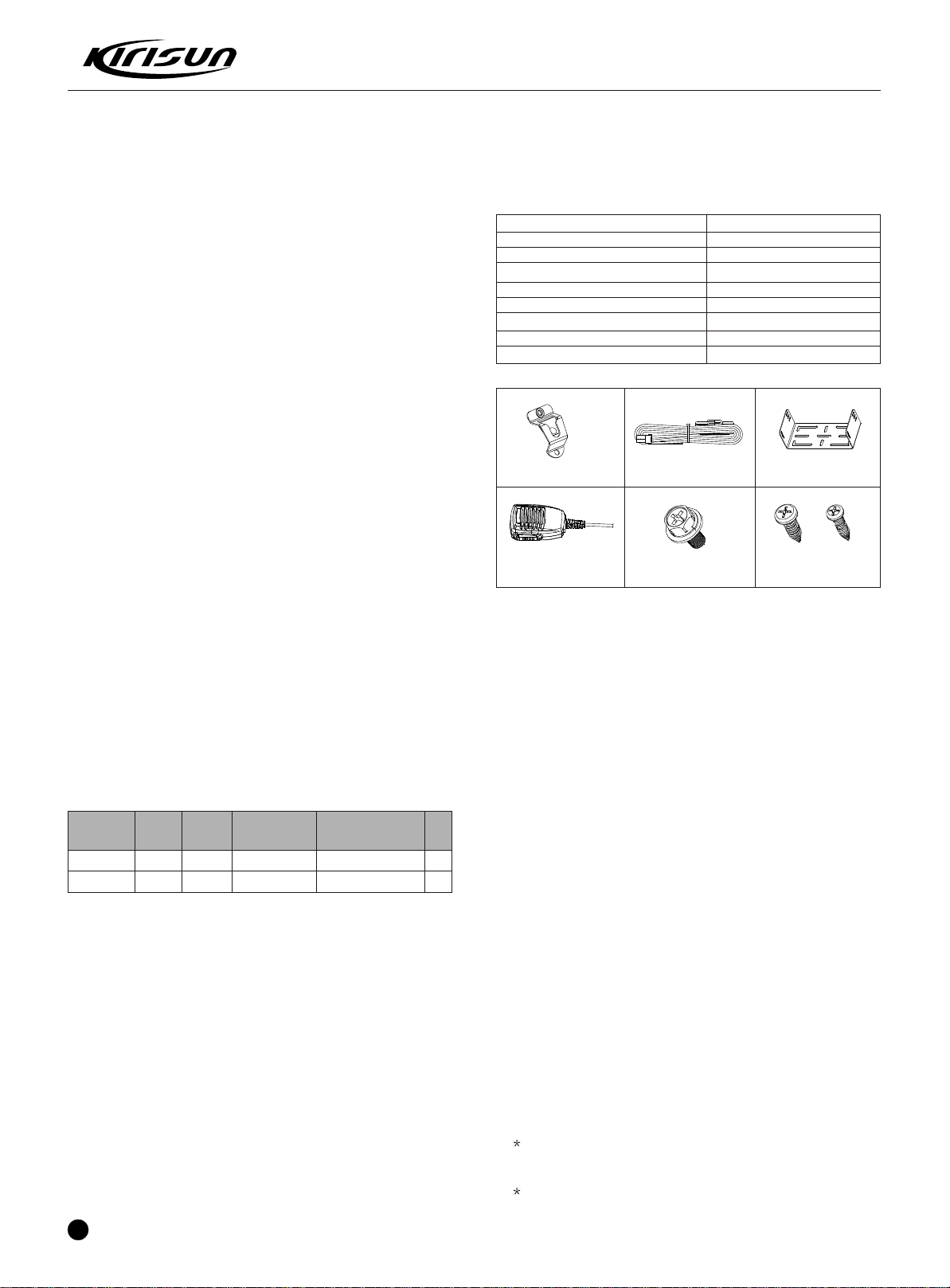
1.Unpack
Please check the host in the package and the supplied accessories in
the following table before using. Any articles are found lost or damaged,
please contact the distributor without delay.
2. Licenses
Rules require that the radio installation point (mobile station or base
station) needs permission license. The license carrier guarantees that
the RF power, frequency and frequency deviation comply with the
license requirements. The radio assembling or operation must be
conducted by the license-authorized technicians.
3. Installation Preparation
3.1 Description
Every radio has been adjusted and checked before the shipment. Before
installation it's better to check if the radio transmitting or receiving is
normal to make sure its proper operation.
3.2 Test
Connect all the cables and accessories to test the radio.
Transmitter frequency, deviation, and power output should be
checked, as should receiver sensitivity, squelch operation, and
audio output. Signllingoperation should beverified.
4. Installation Steps
4.1 Introduction
Check the car and decide how and where to install the radio antenna
and accessories. Allocate the cable in a proper place to avoid pressing
or squeezing it. And pay attention to the heat scattering of the radio
equipments.
4.2Antenna
The most ideal place for antenna is the center of an open and flat
conduction region. It usually at the center of the car top or at the top of the
luggage cabinet. Stick the ground wire at the top of the luggage cabinet
and the car outer shell and make sure to connect the luggage cabinet with
the ground.
4.3 Connection of Power Cable
First of all, please check whether there is a hole for the power
cable on the insulating board. If no, please bore the board with the
suitable drill bit and fix a rubber grommet on it.
Afterwards, please have the cable pass through the insulating
board and lead from the car into the car engine. Connect the red
PT8200 SERVICE MANUAL
1
1
1
1
4
2
4
Accessories
Fixed bracket
Power Cable
Hand Microphone
Microphone Hanger
M4*10 Combination Screw
M4*16 Self-tapping Screw
M5*16 Self-tapping Screw
Instruction Manual
1
Quantity
Fixed bracket
Power Cable
Hand Microphone
Microphone Hanger
M4*10 Combination
Screw M5*16 / M4*16
Self-tapping Screw

3
PT8200 SERVICE MANUAL
conductor to the positive terminal of the accumulator and the black con-
-ductor to the negative terminal.
At last, ring the remained conductor and fix it.
Note: Please maintain the sufficient relaxation of the power cable to
make it convenient to dismantle the radio in the state of power
connection.
4.4 Radio Installing
Warning: For passengers' safety, please fix the radio firmly on the fixed
bracket so that the radio will not be loosened in case of collision.
The fixed bracket is taken as an example. Draw the position and drill a
hole on the instrument panel first, and then install the fixed bracket with 4
M5*16 self-tapping screws. (Note: please fix the radio at the position con-
-venient for operation and control, and leave an enough space for fixation
and connection of the cable.)
Slide the radio into the fixed bracket and fix it with 4 M4*10 combination
screws (plus plain washer and spring washer). (Different combinations of
fixing holesare selectableto adjust the radio tothe properheight andvisual
angle.)
Connect the antenna and the power cable to the radio.
Install the microphone hanger at the position easy to use, with 2 M4*16
self-tapping screws. (The microphone and its cable should be fixed at the
position not affecting safe driving.)
Connect the microphone to the microphone jack on the front
panel of the radio and put it on the hanger.
Note: When replacing the protective tube for the power cable, please
use the one of the same specification without fail. It is not allowed to
change it into the tube of higher capacity.
4.5 If you do not intend to use the external speaker, fit the supplied speaker
-jack cap to stop dust and sand getting in.
Chapter 2 Radio Overview
1 power button
Press this button for a long time (more than 1.5 seconds) to swith the
radio on/off.
2 LED indicator
The red indicator will light while transmitting;the green indicator will
light when it receives the carrier.
The led flashes orange on received correct DTMF/2Tonesignalling.
The red indicator flashes in the scanning process.
2.1 Description of External View
3 / button (programmable button)
4 LCD display screen
For details, see LCD Display .
5 Volume Control knob
To be used to adjust volume.
6 Microphone/Programming Interface
7 button (programmable button)
8 button (programmable button)
9 button (programmable button)
10 button (programmable button)
11 PTT button (on the hand microphone)
Press the PTT button first, and then speak to the microphone to
transmit the voice to the other. Release to receive.
2.2 Display Screen
P1 P2 P3
Display Description
It means the receiving signal strength. 4 lines
means the strongest signal.
Transmission power level
L means the transmission of signal for the
radio at the lower power;
M means the transmission of signal for the
radio at the medium power;
P2
H means the transmission of signal for the
radio at the high power;
Call Received indicator.
The radio receives a selective call/call alert.
Monitor State Indicator.
Scan Indicator.
Companding Indicator.
Talkaround Indicator.
Scrambler Indicator.
OST Indicator.
2.3 Rear Panel
1 Antenna Interface
2 Power Interface
3 15-Pin Connector for accessories.
4 External Speaker Interface
2.4 Programmable Button Function
/ can be programmed as
one of the following functions.
Buttons Function Description
0. None No function
1.Channel Up Select the next channel
2.Channel Down Select the previous channel
3.Zone Up Select the next zone
4.Zone Down Select the previous zone
5.Display Channel
Frequency
6.Display Channel
Name
7.Display Mode
Switch
8.OST Change the setup of preset CTCSS/DCS for the
current channel.
Press this button and the LCD will show the
frequency of the current channel.
Press this button and the LCD will show the
name of the current channel.
Press this button and the LCD will show
Channel Number , Channel Name ,
Zone Number, Zone Name and Channel
Frequency alternately.

4
PT8200 SERVICE MANUAL
Buttons Function Description
11.Key lock To toggle between locking/unlockingyour radio
keypad.
12.Scan Start/end the scanning function of system.
13.Nuisance
Delete
14. Voice
Companding
15. Public
Address
16.Scrambler Enable or Disable voice scrambler function.
17. Home
Channel
18.Talkaround
19.VOX Selection
20. Monitor
momentary/
Call Cancel
When one channel continually generated
unwanted noise,this allow you temporary remove
the channel from the current active scan.
Start/end the voice compression/expansion
function.
Start/end the public address function.
Press this button and the function will be actived.
Press the PTT button and speak to the micro-
-phone so that you can hear your voice through
the external speaker . Press this button once
again and return to the normal user mode.
Changes to the home channels.
Enable or disable the VOX function.
Switch the radio between talkaround and
repeater mode.
Hold this button to close CTCSS, DCS, 2Tone
/DTMF signalling according to the set data.
Loosen this button to return to the normal
operation. Press this button in the selective call
Press this button to enter the Squelch Level
Adjustment Mode first, and then press the
/ button to adjust the level. Press the button
to save the selected squelch level and
quit this mode.
Press this button to make selection among the
high, medium and low transmission power, and
H , M and L will be shown on the LCD
to represent the current transmission power.
9.Power level
Selection
10.Squelch Level
Selection
21.Monitor/
Call Cancel
22.Squelch off
monmentary/
Call Cancel
23.Squelch off
/Call Cancel
24.Emergency
Alarm
25.Radio Call
Press this button to trigger this function and the
CTCSS, DCS, 2Tone/DTMF signalling will be
closed, so you can receive the signal that can't
be heard in the normal operation. Press this
button again to return to the normal operation.
Press this button in the selective call state to quit
such a state.
Hold this button to open the squelch. loosen this
button to return to the normal operation.
Press this button in the selective call state to quit
such a state.
Press this button to open squelch, press it again
to returm to normal operation.Press the button in
the selective call state to quit such a state
Enables the emergeney mode.
Press this button and to enter the shortcut menu
mode of Radio Call .For detailed operation,
see Menu Operation .
state to quit such a state.
26.Call Button 1 Sends the DTMF/2Tone code assigned to call
1 key.
27.Call Button 2 Sends the DTMF/2Tone code assigned to call
2 key.
28.Call Button 3 Sends the DTMF/2Tone code assigned to call
Buttons Function Description
29.Call Button 4
30.Menu Select
/Enter
31.Horn Alert
32.Tenancy
33.Lone worker
34.Scan List Edit
To enter the menu mode or make menu
selections.
Enables the horn alert
Enables lone worker function
Press this button and the radio will enter the
fast menu mode for scan list edit. For details,
see Menu Operation .
3 key.
Sends the DTMF/2Tone code assigned to call
4 key.
Press this button to view tenancy remained time.
35.GPS
Information View
36.VOX Level
Selection
Press this button and the radio will enter the
menu mode of GPS Information Menu.
Press this button to enter the VOX Level Adju-
-stment Mode . Press / button to adjust
VOX level. Press button to save the selected
VOX level and quit this mode.
Chapter 3 Mode Combinations
Mode Function Howto access
User Mode Fornormal use Poweron
Hold buttons and
, andconnect the
power at the same time
Hold while
connecting the power,
release to enter
the user mode.
Data Progra-
-mming mode
Test Mode
Firmware Pro-
-gramming Mode
Reading and writing
frequency data and
other functions
Receive instructions
from the PC
PC
Mode Used to tune the radio
using the PC.
Upgrades the software
when new features are
added
Receive instructions
from the PC
Receive instructions
from the PC
Wired Clone mode
Firmware Version
Information Display
Mode
Used to transfer
programming
data from one
radio to another.
Displays the firmware
version information
Mode combinations
Data programming mode:
Before leaving the factory, the radio has been set in factory. However,
due to different requirements of users, functional parameters of the
radiolikeworking frequency, channels,CTCSS/DCS and auto scanning,
etc. should bereset.Therefore, the company has specially designed a
set of Chinese/English programming software KSP8200 with friendly
interface, convenient operation and visualized display for setting
functional parameters of the radio.

5
PT8200 SERVICE MANUAL
Steps for setting the functional parameters of the radio by PC are as
follows:
A.Install KSP8200 on the PC.
B.As shown in the figure below, connect the radio and the serial port
of the PC with the special programming cable KSPL-05
C.Turn on the power of the PC.
D.Turn on the power of the radio.
E.Click on KSP8200 to perform the program and run KSP8200.
F.Inthemain menu ofKSP8200,click on [Read]toread the parameters
of the radio into the PC; click on [Write] to write the parameters set in
the PC into the radio.
G.As required by the user, the following parameter settings can be
made with KSP8200:
1 Programmable key functions
2 Alert tone
3 Optional functions
4 2-tone/DTMF/MDC/5-tone signaling setup
5TOT
6 Emergency alarm
7 Personality template
8 Scanning function
9 Channel data
Please refer to the Help document of KSP8200 for details.
Caution:
1 Turn off the power of the radio before connection.
2 When reading data from the radio, the indicator of the radio is green,
do not press the PTT during programming; when writing data to the
radio, the indicator of the radio is red.
3 Before editing for the first time, the data should be read from the
radio and properly backed up.
4 If the edited data cannot work normally after being written into the
radio, please open the backup data and rewrite them.
5 Model Information is important information of the radio and
should not be altered.
6 Upon completion of the programming, the radio will be automatically
restarted and return to the User Mode.
PC
(RS232 serial
port)
Programming
cable
KSPL-05
Radio
(MIC/Program
port)
Figure 5-1
Test Mode
According to Figure 5-1, connect the radio and the serial port of the
PC with the special programming cable.
Warning: Before entering the Test Mode, please first connect a high-
frequency load of 50 ohm to the antenna port of the radio or connect
the radio to a comprehensive tester.
With the KSP8200 software, enter the adjustment status in the Comp-
-uter Test Mode, you can adjust the following parameters of the radio:
1)Frequency
2)Low/Med/High Power;
3)Max deviation
4)Tone deviation
5)DTMF deviation
6)MSK deviation
7)DCS balancing
8)DCS deviation
9)VOX1-level/10-level
10)CTCSS(67Hz) deviation
11)CTCSS(254.1Hz) deviation
12)Receiving sensitivity
13)9-levle/1-level Squelch open
14)9-levle/1-level Squelch close
15)RSSI
Firmware Programming Mode
The radio is equipped with FLASH ROM internally, when new fea-
-tures are announced, it can be upgraded.
1).Connect the power and enter the User Mode.
2).Run PC software KMU.
3).Connect the radio and the PC with the programming cable.
4).Selectthecorrect serial port,selectsuitable baud rate according
to the actual situation, 19200 is recommended, and then click on
E.P or E.P.R for downloading. The LCD displays FIRM-
-WARE
5).Press OK to quit after the communication is successful.
6).Just repeat steps 1-5 if you want to program more radios.
Chapter 4 Disassembly For Repair
Exploded view ofthe radio
35
34
33
32
31
30
29
28
27
26
25
24
23
22
21
20
19
18
17
16
15
14
13
12
11
10
09
08
07
06
05
04
03
02
01
N
6800 knot circlip
PT7200 coding switch nut
PT8200 static protection film
PT8200 dustproof screen for horn
Horn
B/W twisted-pair
PT8200 horn gasket
Flat cable
M3.0x25.0 machine screw
PT8200 aluminum alloy lower cover
PT8200 power module screen
M3.0x6.0 machine screw
Electric cable
PT8200 e-material of main board
M2.5x5.0 machine screw
PT8200 metal baffle
PT8200 plastic buckle
PT8200 horn hole plug
M3.0x10.0 sems screw
PT8200 antenna head
Silver-coated jumper cable
PT8200 upper/lower cover gaskets
PT8200 Aluminum alloy upper cover
PT617A VCO screen
PT8200 L/R gaskets of panel
PT8200 Lower gasket of panel
PT8200 Upper gasket of panel
M2.6x6.0 tapping screw
PT8200 E-material of keyboard
PT8200 LCD
PT8200 silicon key
PT8200 light guide
PT8200 lens
PT8200 plastic panel
PT8200 volume knob
Name
203-006800-R26
203-007200-R08
204-008200-R08A
204-008200-R07A
121-100000-R19
120-400000-R04
204-008200-R06A
120-400000-R05
301-30250D-R01
203-008200-R02A
203-008200-R05A
301-30060G-R01
120-100000-R15
602-082001-H01
301-25050J-R01
203-008200-R04A
201-008200-R03A
202-008200-R02A
303-30100G-R01
203-008200-R03A
120-500000-R08
204-008200-R04A
203-008200-R01A
203-00617A-R01
204-008200-R03A
204-008200-R02A
204-008200-R01A
302-26060D-R01
602-08200K-H01
107-008200-R01
202-008200-R01A
201-008200-R05A
201-008200-R04A
201-008200-R01A
201-008200-R02A
Material Code
1
1
1
1
1
1
1
1
9
1
1
8
1
1
6
1
1
1
7
1
1
2
1
1
2
1
1
6
1
1
1
1
1
1
1
Quty.
O.

6
PT8200 SERVICE MANUAL
. Instruction for disassembly of the station for maintenance
1 RF-PCB Disassembly
.Release the 9 screws (M3x25) for the upper and lower covers, open
the aluminum alloy lower cover (see the left figure below).

7
PT8200 SERVICE MANUAL
.Release the 4 (M2.5x5) screws of the baffle and the 2 fixing screws
of the 15PIN DB socket, remove the metal baffle, the plastic buckle
and the horn hole plug (see the right figure above).
.Remove the power module screen, release the fixing screws of RF
-PCBand audiopoweramplifier,DC regulating IC,unplugthe flat cable
andthe horn cable, welderthe antenna head andthe power module to
separatethem from theRF-PCBwith the electriciron,carefully remove
the RF-PCB from the aluminum ally upper cover (see the left figure
below)
2 Instruction for disassembly of KEY-PCB
.Unplugthevolume knob, removetheknob circlip andtheswitch nub,
release the 2 M2.5x5 screws for the panel to separate the panel from
the station, separate the horn cable and the horn with an electric iron,
plug out the flat cable to separate the panel with the entire station thor-
-oughly (see the right figure above)
.Release the 6 (M2.6x6) fixing screws for KEY-PCB to take out the
KEY-PCB from the plastic panel (see the figure below)
After the disassembly above, you can carry out corresponding repara-
-tion and adjustment according to the actual malfunction.
Chapter 5 Circuit Description
Circuit composition
ANT SW
D31 D30 RF AMP
Q26 IF SYSTEM
TA31136
MCF
XF1 XF2
RF MAP
RA601317 MIC
AMP
MB15E03 PLL/VCO
CIRCUIT
AF AMP
TDA1519
1st
MIX
Q21
AUDIO
CONVERTER
AK2346
450KHZ
CF1 CF2
SP
MIC
AUTO
AGC
TCXO
16.8MHZ
RX/TX
SWD19 ½
UPB1509
DIVIDE
R AMP
Q23/Q25
16.8MHZ*3
APC
CONTROL MCU
LCD DRIVER
ALL I/O
Thereceivingcircuit adopts doubleconversionsuper-heterodyne mode.
The first IF is 49.95MHz; the second IF is 450kHz. The first local frequ-
-encysignalis provided bythephase-locked loop bycontrollingthe VCO
circuit. The 2nd local frequency signal is provided by the 16.8MHZ
crystal triple frequency.
The transmission frequency is generated by the phase-locked loop by
controlling VCO circuit via the frequency dividing circuit for further
frequency division. The composition ofthe circuit is shownin the figure
above.
Transmission Protection
The power module is provided with overheating protection when
transmitting.When the temperature ofthe power module ishigher than
the reference value, the communicator will switch the TX power from
highpower tolow power.Subsequently, if thetemperaturekeeps rising,
the transmission will be stopped
Over-voltage and over-current protection of the power
When the voltage is higher than the reference value of 18V, the
communicator will automatically switch the power control and turn on
oroffthe power. When thereceivingcurrent is higherthanthe reference
valueandwhen the polarityofthe power isreverse,the F841 onthePCB
of the station will automatically cut the power supply.
Receiving System
ANT SW
D31 D30 RF AMP
Q26 IF SYSTEM
TA31136
MCF
XF1 XF2
MB15E03 PLL/VCO
CIRCUIT
AF AMP
TDA1519
1st
MIX
Q21
AUDIO
CONVERTER
AK2346
450KHZ
CF1 CF2
SP
TCXO
16.8MHZ
RX/TX
SWD19 ½
UPB1509
16.8MHZ*3

8
PT8200 SERVICE MANUAL
1st High frequency amplifier
Signals entering the antenna enters RF amplifier (Q26) via the trans-
-mitting/receiving switching circuit (D30/D31) and the band-pass filter
(L48, L38 and variodes: D50, D26). After being amplified, the signals
are filtered by the band-pass filters (L30, L51 and the variodes: D21,
D22) before entering the 1st mixer (Q21).
1st mixer
Signals from RF amplifier and the 1st local frequency from VCO are
synthesized to generate the 1st IF of 49.95MHz. And then the 1st IF
enters the 2 single-chip crystal filter (XF1 XF2) for further elimination
of parasitic signals and then sent to the IF amplifier
IF amplifier
After being amplified by Q19, the 1st IF signal enters U102 (Ta31136).
When the signal is mixed with the 2nd local signal in U102 again, the
2nd IF signal of 450kHz is generated. Before being amplified, the 2nd
IFenters the 450kHzceramicfilter (broad: CF1,narrow:CF2) for further
elimination of unnecessary signals as well as modulation and demo-
-dulation in U102.
Parameters of thereceiving components
Item Rated Value
Rated central frequency 49.95MHz
Pass band width 5.0kHz or higherat 3dB
35dB stop bandwidth 20.0kHz or lower
Pulse 1.0 dBor lower
Insertion loss 5.0dB or lower
Guaranteed attenuation 80dB or higherat fo 1MHz
Parasitic signal:40 dB or
higher withinfo 1MHz
Terminalimpedance 350 /5.5pF
Table1 Crystal filterXF1/XF2
Item
Rated central frequency
Pass band width
35dB stop band width
Pulse
Insertion loss
Guaranteed attenuation
Terminal impedance
Rated Value
450kHz
6.0kHz or higher
12.5 kHz or lower
2.0 dB or lower
6.0 dB or lower
35.0 dB or higher within fo 100kHz
2.0k
Table2 Ceramic filterCF1
Item
Rated central frequency
Pass band width
35dB stop band width
Pulse
Insertion loss
Guaranteed attenuation
Terminal impedance
Rated Value
450kHz
4.5kHz or higher
10.0 kHz or lower
2.0 dB or lower
6.0 dB or lower
60.0 dB or higher within fo 100kHz
2.0k
Table3 Ceramic filterCf2
Broad/Narrow switching circuit
The broadband control port (pin 51) and narrowband control port (pin
52) of the CPU are used for switching between ceramic filters. When
the broadband control port is at high level, the ceramic filter SW diode
(D13, D15) allows the CF1 to receive broadband signals. When the
narrowband control port is at high level, the ceramic filter SW diode
(D13, D15) will allows CF2 to receive narrowband signals (The circuit
is shown in the figure below).
IF demodulation TA31136
1
CF1
Wide
CF2
Narrow
D13 D15
Narrow
U401 PIN52
Wide
U401 PIN51
R74 R78
R73
R77
PIN 5PIN3
Audio signal system
Detection signals from the IF IC (U102) enters the amplifier (U601) for
adjusting the gain and be outputted to AK2346(U404) for baseband
signal processing, the output signals are inputted to the audio power
amplifier(U11)for amplification andthenbe outputted fromthespeaker.
Squelch circuit
Noise signals outputted from FM IF chip (U102) output are amplified
bythevoice amplifier (Q78),theDC voltage correspondingtothe noise
level is regulated and outputted, the DC voltage is then sent to the
analog port of the CPU. U102 also outputs the DC level RSSI corres-
-ponding to the IF amplifier input signals.
Phase-locked loop frequencycombiner
The phase-locked loop and the voltage controlled oscillator circuit
produce the 1st local oscillation signal of the receiver and the transm-
-itting signals of the transmitter.
Phase-locked loop circuit
The frequency step of the phase-locked loop circuit is 2.5/5.0/6.25kHz.
The reference oscillator signal of 16.8MHz is divided in the chip U101
through a mixer counter to produce reference frequency of 2.5/5.0
/6.25kHz.Signalsoutputted from thevoltage controlled oscillator(VCO)
arebuffered andamplified via Q15 and thendivided by the dual-mode
programmable counter in chip U405. Signals amplified by Q15 are
compared with phase comparators carrying reference signals with
2.5/5.0/6.25kHz in chip U101. Signals output from the phase compar-
-ator controls the voltage to enter a low-pass filter and to control the
oscillation frequency through the voltage controlled oscillator.
Voltage controlled oscillator
The RF rate is generated via Q11 in the transmission mode, the recei-
-vingfrequencyis generated viaQ10in the receivingmode.The control
signalsgenerate voltage via thephase comparator to thevariode (D10
andD12 in thetransmissionmode, D9 andD11 in thereceivingmode).
In the receiving mode, Q12 is cut and Q7 is connected, in the transm-
-issionmode,Q12 is connectedandQ7 is disconnected.Outputsignals
from Q10 and Q11 are amplified by Q15 and sent to U405 frequency
divider.

9
PT8200 SERVICE MANUAL
Transmitting system
Block diagram
ANT SW
D31 D30
RF MAP
RA601317 MIC
AMP
MB15E03 PLL/VCO
CIRCUIT
AUDIO
CONVERTER
AK2346
MIC
AUTO
AGC
TCXO
16.8MHZ
RX/TX
SWD19 ½
UPB1509
DIVIDE
R AMP
Q23/Q25
APC
CONTROL
he transmitting circuit directly produces and amplifies the required
frequency and conducts frequency modulation for carrier signals via
the variode.
Transmitting drivingpower amplifier circuit
ANT
switch
D31 D30
Power
amplifier
RA601317
RX/TX
switch
D19
Drive
amplifier
Q23/Q25
Low-pass
filter
Transmittingsignalsfrom the voltagecontrolledoscillator are amplified
throughthe frequency division and transmission/receiving selector
diode(D19) andthedriving amplifier(Q23and Q25), thus providingthe
power moduleRA601317M/(RA554047M) with a special level. The
amplified signals then enter a low-pass filter. The low-pass filter
eliminates unnecessary high-frequency harmonics and the acquired
signals enter the antenna terminal.
Auto power control circuit
The auto transmitting power control (APC) circuit adopts the diodes
(D34, D36) to detect part of the power module outputs and provide
control voltage for U202. Through comparison with the reference
voltage outputted from MCU input, U202 generates the error voltage
and outputs from pin 7 of U202 to control the power amplifier Ra6013
17M and transmits output power stable. The composition of the auto
powercontrol circuit is forpreventing over current ofthe power module
dueto the fluctuationofthe load oftheantenna terminal andstabilizing
the output voltage and temperature change of transmission.
Control circuit
The CPU is provided with the following tasks:
1)Embedded Flash Rom, including the control program
2)Controlling the receiving circuit
3)Controlling the transmitting circuit
4)Controlling the display circuit
5)Various function control circuits
6)Communicating data with external devices
Storage circuit
The radio is provided with a 256k-bit EEPROM (U402) for storing pro-
-gramming or testing data.
Display circuit
The display circuit consists of the CPU (U401), the LCD component,
LED and other components. When the communicator is busy and the
LEDG cable is at high level, Q4 is connected and the green LED (D11)
is on. When transmitting, the LEDR cable is at high level, Q8 is conne-
-cted and the red LED (D12) is on, Led D1 to D4 provide the LCD back-
-light, which is on when operating the radio. The LCD is in the *
shape and can display up to 8 digits or letters.
Encoding
CTCSS/DCS:
Outputting CTCSS/DCS signals from the CPU(U401); one channel is
outputted from PIN24 via the low-pass filter and mixed with audio
signals and the external pin DI line, then inputted to the VCO for mod-
-ulation; the other channel is outputted from PIN28 output to TCXO(XI)
for modulation.
2-TONE/5-TONE/DTMF:
PIN2ofthe CPU outputs2-TONE/5-TONE/DTMFcoding signals, which
are inputted to the baseband processing IC (U404) via low-pass CR
filter for filtration and deviation control and then sent to the VCO for
modulation.
MSK:
MSK signal is generated by U404, through filtration and frequency
deviation control, it is outputted from PIN7 and sent to VCO for
modulation.
Decoding
CTCSS/DCS
CTCSS/DCS signals are processed and amplified by U403 filter and
sent to PIN92 of MCU for filtration and decoding.
2-TONE/5-TONE
2-TONE/5-TONEsignalsare filtered andamplifiedby U503 andreceive
waveform transformation via U801 (sine wave into square wave) and
then sent to PIN3 of MCU for filtration and decoding.
DTMF
DTMF signals are filtered and amplified by U503 and sent to PIN2 of
U803 (HT9172) for decoding.
MSK
MSKsignals are filtered,amplified and decoded byU404 and then sent
to MCU for MSK signal processing and control.
Power circuit
When the POWER switch on the front panel is pressed, the port
connecting the POWER on the display board and the terminal pins of
the CPU is at low level, Pin 80 (SBC) of the CPU is as high level, Q34
is connected, SB SW (Q42) is connected and supplying power to the
communicator (SB). This circuit is provided with the over-voltage prot-
-ection circuit. If 17V or higher voltage is provided to the power cable,
D839 will be connected and supply voltage to the base of Q38. This
voltage makes Q38 connected and Q34 and SB disconnected.
Chapter 6 Semiconductor Data
Processor: M30620
Pin
1
2
3
4
5
6
7
Port Name
PC/TV
DTMF
HSDI
EEP DAT
EEP CLK
BYTE
CNVSS
In/Out
O
O
I
I/O
O
I
I
Function
Transmit power and receive sensitivity
adjusting voltage output
DTMF/2Tone/5Tone/Beep output
Hi-speed data input
EEPROM data input/ output
EEPROM clock output
GND
GND

PT8200 SERVICE MANUAL
8
9
10
11
12
13
14
15
16
17
18
19
20
21
22
23
24
25
26
27
28
29
30
31
32
33
34
35
36
37
38
39
40
41
42
43
44
45
46
47
48
49
50
51
52
53
54
55
56
57
58
59
60
61
62
63
BSHIFT
EXT SPK
RESET
XOUT
VSS
XIN
VCC
NMI
DTMF DV
RDT
TCLK
SCLK
FreqStab
TDATA
SideToneVol
DI/O
CTCSSVCO
DIR
HNC
-
CTCSSTCXO
TXD1
RXD1
CLK1
RTS1
TXD0
RXD0
RX W/N
TX W/N
RX SW
TX SW
HOLD
PLL UL
PLL STD
PLL DAT
PLL CLK
RD
PLLT/R
-
-
Au2
Aux1
PTT C
W/N R1
W/N R2
AFCON
RX MUTE
PSW
LCD RST
LCD BLC
LCD DAT
LCD WR
VCC
LCD RD
VSS
LCD CS
O
O
I
O
-
I
-
I
I
I
I
O
O
O
O
I/O
O
O
O
-
O
O
I
-
-
O
I
O
O
O
O
-
I
O
O
O
-
O
-
-
I/O
I/O
O
O
O
O
O
I
O
O
I/O
O
-
O
-
O
Clock selection control
External SPK conversion
CPU reset input
CPU clock output
GND
CPU clock input
+5v
+5v
DTMF decoding detection
AK2346 MSK signal receiving symbol
and frame detection input
AK2346 MSK data transmission clock
input
AK2346 serial clock output
Frequency control output
AK2346 MSK data output
Side tone volume control output
AK2346 serial data input output
CTCSS/DCS output to the VCO
AK2346 serial data input/ output control
Speaker alarm control output
NC
CTCSS/DCS output TCXO (PWM)
PC serial data output
PC serial data input
NC
NC
GPS serial data output
GPS serial data input
Receive broad/narrow band switch
Transmit broad/narrow band switch
Receiving VCO switch
Transmitting VCO switch
GND
PLL loss of lock detection input
PLL enabling control output
PLL serial data output
PLL clock output
NC
PLL transmitting/receiving switch output
NC
NC
Programmable auxiliary input/output
Intermediate PTT control output
Receive IF broad/narrow band switch
Audio power amplifier control output
Receive mute switch
Power key input
LCD reset control
LCD backlight control output
LCD serial data input/ output
LCD writing clock output
+5v
LCD reading clock output
GND
LCD chip selection signal output
Pin Port Name In/Out Function Pin Port Name In/Out Function
64
65
66
67
68
69
70
71
72
73
74
75
76
77
78
79
80
81
82
83
84
85
86
87
88
89
90
91
92
93
94
95
96
97
98
99
100
KEY BLC
P4
P3
P2
P1
Down Key
Up Key
R LED
G LED
SideToneFixed
MBLC
MIC DAT
HOOK
PTT
MinVol
Int Mic Mute
8T C
8R C
SBC
DTMF D3
DTMF D2
DTMF D1
DTMF D0
NC
TEMP
RSSI
BUSY
VOX
TI
DTMF IN
AVSS
PA C
VREF
AVCC
IGN
Ext Mic Mute
HPF PC
O
I
I
I
I
I
I
O
O
O
O
I/O
I
I
O
O
O
O
O
I
I
I
I
I
I
I
I
I
I
I
-
O
-
-
I
O
O
Front panel keypad backlight control
output
P4 key
P3 key
P2 key
P1 key
Down key
Up key
Transmit LED control
Receive LED control
Fixed side tone volume control
MI keypad backlight control
MIC keypad serial data
Hangup signal input
PTT input
Min. Volume control
MIC mute switch
8T power control
8R power control
SB power control output
DTMF receiving signal input
NC
Temperature detection input
Receiving field intensity signal input
Squelch level detection input
VOX voltage detection input
CTCSS/DCS decoding input
DTMF decoding input
GND
Speech speaker control output
+5v
+5v
Ignition sensor input
External MIC mute switch
High-pass filter switch
Chapter 7 Description of Components
Functional description of semiconductor device
Item
U101
U202
U102
IC404
U501
U11
U402
U401
U305
Q23
Q25
Q16
Q20
Q14
Model
MB15E03
TC75W51
TA31136
AK2346
TC75W51FU
TDA1519C
AT24C256
M3062LFGPGP
PST9140NR
2SC3357
2SC3357
2SC4226
2SC4627
2SC4617
Function Description
Phase-locked loop chip
APC driver
IF demodulation
Baseband audio processor
MIC amplifier
AF Power AMP
EEPROM
MCU
Voltage detector reset
Transmitter1st amplifier
Transmitter 2nd amplifier
VCO buffering amplifier
VCO power filter
10

11
PT8200 SERVICE MANUAL
Q78
U201
Q70
Q423
Q21
Q26
Q19
Q605
Q701
Q30/Q29
Q7
Q12
2SC2412K
RA601317M
DTA144EE
DTA144EEAPC output
switch
3SK3181st mixer
3SK318RF amplifier
2SC46271st IF amplifier
KRC102SAF Mute
2SC4617LED driver
RAC102S8T/8R switch
2SJ243TX switch
2SJ243RX switch
Noise amplifier
Transmitting final power
amplifier IC
Wide/narrow band switch
APC output switch
1st mixer
RF amplifier
1st IF amplifier
AF Mute
LED driver
8T/8R switch
TX switch
RX switch
Item Model FunctionDescription
Diode functional description
Item
D30
D19
D34/D36
D31/D32
D501/D68
D10
D12
D9
D11
D308
DD1/D902
D6
D16
D18
D70
D13/D15
D21/D22
D26/D50
Model
MA4PH633
DAN235
MA742
MA4P1250
MA742
ISV325
ISV325
ISV278
ISV325
ISV325
HZU5ALL
MA2S111
MA2S111
Ma742
LED red and green
DAN222
ISV305
ISV305
Function Description
Transmitter antenna switch diode
VCO output switch
Power detection diode
Receiver antenna switch diode
AGC control diode
Transmit VCO oscillation varicap
VCO adjust diode
Receive VCO oscillation varicap
Output voltage-limiting diode
Loss of lock detection diode
VCO power supply strain
accelerate diode
Noise demodulation
Transmit receive indication
Wide narrowband filter control diode
Receive band pass varicap
Characteristic of XF1/XF2 crystal filter
Item
Nominal center frequency
Transmission band width
40dbstop band width
Ripple
Insertion loss
Ensure attenuation
Terminal impedance
Rated Value
49.95mhz
7.5khz or higher, but within 3db
20.0khz or lower
1.0db or lower
3.0db or lower
80db or higher, but between fo-910khz
1.5k /6pf
Performance and parameter cf1 CF1 LTWC450F
Item
Nominal center frequency
6db band width
50db band width
Ripple
Insertion loss
Ensure attenuation
Rated value
450khz
5.0khz or higher
13.5khz or lower
3.0db or lower
7.0db or lower
45.0db or higher, but between f0 100khz
Performance and parameterCF2 LTWC450G
Item
Nominal center frequency
6Db band width
50dB band width
Ripple
Insertion loss
Guaranteed attenuation
Rated Value
450kHz
3.5kHz or higher
12kHz or lower
3.0dB or lower
7.0dB or lower
45.0dB or higher, between
f0 100kHz
Semiconductor device packaging sketch
3SK318
M: YB-
G1
G2 D
S
G
S
D
CCC
C
B
BB
B
EE
E
E
G
D
S
2SK18 24
Mark: B1
2SC5108
M: MC
C
B
E
M: R24
2SC3356
C
B
E
2SC4617
C
B
E
C
B
E
2SC473 8 KTC4082
C
B
E
2SC1623
M: L6
KTA1298 DTC144EE
M:16
GND
IN
OUT
HT7150-1
RD01MUS1 D
G
SS
RD07MVS1
RDA0002 1
2
3
DA221
M: K
2SK308NV
DTA144EE
C
B
E
FMMT591
GSD
PT8200 mainboard BOM / 136-174MHz
1
2
3
4
5
6
7
8
9
10
11
12
No Material SerialNo. Name/Spec. Quantity Installation Positon
101-08200V-R04
102-1509GV-R01
102-24C256-R02
102-601317-R01
102-7808CV-R01
102-9140NR-R01
102-A1519C-R01
102-A31136-R01
102-A75W01-R01
102-AK2346-R01
102-B15E03-R01
102-C75W51-R01
PT8200PCB ,PT8200V-080430.PCB,ROHS
Frequency demultiplier/ UPB1509GV ROHS
Memory IC / AT24CL256AN ROHS
Power module / RA60H1317M ROHS
In-line regulator IC / L7808CV,TO-220 ROHS
Restoration IC / PST9140NR,ROHS
Audio power amplifier / TDA1519C,SIL9,ROHS
IF(FM)demodulationIC / TA31136FN,SSOP ROHS
Operational amplifier / TA75W01FU,ROHS
IC / AK2346 ROHS
PLL IC / MB15E03SL,PLL,16-PIN,SSOP,ROHS
Operational amplifier / TC75W51FU,SSOP8-P-0.65,ROHS
1
1
1
1
1
1
1
1
1
1
1
5
U405
U402
U201
U302
U305
U11
U102
U202
U404
U101
U601, U403, U501, U503, U801

12
PT8200 SERVICE MANUAL
13
14
15
16
17
18
19
20
21
22
23
24
25
26
27
28
29
30
31
32
33
34
35
36
37
38
39
40
41
42
43
44
45
46
47
48
49
50
51
52
53
54
55
56
57
58
59
60
61
62
No Material SerialNo. Name/Spec. Quty Installation Positon
102-FP3502-R01
102-HT9172-R01
102-M3062L-R01
102-M78L05-R01
103-00DZ18-R01
103-00MA77-R01
103-0DA221-R01
103-0MA742-R01
103-1SS355-R01
103-1SV278-R01
103-1SV305-R01
103-1SV325-R01
103-4PH633-R01
103-A2S111-R01
103-AP1250-R01
103-DAN222-R01
103-DAN235-R01
103-HZU5AL-R01
103-HZU5CL-R01
103-SM3MA1-R01
104-A123JE-R01
104-A144EE-R01
104-C114EE-R01
104-C144EE-R01
104-KRC102-R01
104-KRC404-R01
104-SA1641-R01
104-SA1745-R01
104-SA1774-R01
104-SA1832-R01
104-SC2412-R01
104-SC3357-R01
104-SC4116-R01
104-SC4226-R01
104-SC4617-R01
104-SC4649-R01
104-SC4738-R01
104-TA1664-R01
105-2SJ243-R01
105-2SK508-R01
105-3SK318-R01
105-SK1824-R01
106-00G5V1-R01
108-CF450F-R01
108-CF450G-R01
108-XF4995-R01
109-060000-R01
109-060100-R01
109-060101-R01
109-060102-R01
Regulator IC / XC62FP3502PR,SOT-89,ROHS
DTMF decode IC/ HT9172,sop, ROHS
CPU / M16C-M3062LFGPGP,FLASH,100P6Q-A,ROHS
Regulator IC / NJM78L05UA ROHS
Chip regulator diode / 02DZ18(X.Y),ROHS
Chip HF on-off diode / MA77,0805,ROHS
Chip array diode / DA221(ROHM)
Chip on-off diode / MA742(PANASONIC),ROHS
Chipdiode / 1SS355B,ROHS
Chip variable capacitor diode / 1SV278,ROHS
Chip variable capacitor diode / 1SV305,ROHS
Chip variable capacitor diode / 1SV325,ROHS
Chipdiode/ MA4PH633 ROHS
Chip on-off diode / 0603,MA2S111(PANASONIC),ROHS
Chipdiode / MA4P1250-1072T,ROHS
Chip on-off diode / DAN222,(ROHM),ROHS
Chipdiode / DAN235E,ROHS
Chip regulator diode / HZU5ALL(HITACHI),ROHS
Chip regulator diode / HZU5CLL,ROHS
Chipdiode / DSM3MA1,ROHS
Chip triode / DTA123JE(ROHM),ROHS
Chip triode / DTA144EE(ROHM),ROHS
Chip triode / DTC114EE(ROHM),ROHS
Chip triode / DTC144EE(ROHM),ROHS
Chip triode / KRC102S,ROHS
Chip triode / KRC404RTK,ROHS
Chip triode / 2SA1641(S.T),ROHS
Chip triode / 2SA1745(6,7),ROHS
Chip triode / 2SA1774(Q R) ROHS
Chip triode / 2SA1832(G R),ROHS
Chip triode / 2SC2412K,ROHS
Chip triode / 2SC3357 ROHS
Chip triode / 2SC4116-GR ROHS
Chip triode / 2SC4226(R24),ROHS
Chip triode / 2SC4617(S)(ROHM),ROHS
Chip triode / 2SC4649(N,P), 2SC4627 ROHS
Chip triode / 2SC4738(GR),AF,AMPLIFIER(TOSHIBA),ROHS
Chip triode / KTA1664(Y),ROHS
Chip FET (field-effect transistor) / 2SJ243,ROHS
Chip FET / 2SK508NV(K52),ROHS
Chip FET / 3SK318,ROHS
Chip FET / 2SK1824,ROHS
Plug-in Relay / G5V-1,Work voltage 9V/DC,ROHS
Plug-in porcelain filter / LTM450FW,450kHz 7kHz,ROHS
Plug-in porcelain filter / LTM450GW,450kHz 5kHz,ROHS
Plug-in IF filter / 49.95MHz 7.5KHz,U-5*2,ROHS
Chip resistor / 0603,0R 5%,ROHS
Chip resistor / 0603,10R 5%,ROHS
Chip resistor / 0603,100R 5%,ROHS
Chip resistor / 0603,1K 5%,ROHS
1
1
1
3
1
1
1
7
4
1
4
4
1
2
2
2
1
2
1
1
1
1
4
2
4
1
1
1
1
1
1
2
2
1
4
4
1
1
2
2
2
7
2
1
1
2
20
3
13
47
U304
U803
U401
U301, U303, U333
D839
DD2
D23
D65, D66, D18, D68, D34, D36, D501
D58, D558, D27, D518
D14
D21, D22, D26, D50
D9, D10, D11, D12
D30,
D16, D6
D31, D32
D13, D15
D19
D7, D921
DD1
D838
Q85
Q70
Q402, Q482, Q682, Q472
Q403, Q423
Q29, Q30, Q34, Q605
Q38
Q42
Q31
Q94
Q4
Q78
Q23, Q25
Q501, Q531
Q15
Q87, Q88, Q89, Q14
Q20, Q3, Q6, Q19
Q5
Q33
Q7, Q12
Q11, Q10
Q21, Q26
Q50, Q51, Q52, Q53, Q550, Q752, Q711
K101, K102
CF1
CF2
XF1, XF2
L50, R32, R44, R277, R316, R505, R347,
R352, R353, R354, R355, R563, R358, R413,
R559, R5, R315, R346, R887, R367,R15, R112,
R288
R107, R133, R167, R289, R298, R88,
R239, R502, R616, R159, R160, R150, R236
R172, R181, R853, R815, R827, R809,
R814, R10, R281, R808, R689, R664,
R682, R11, R13, R385, R386, R387, R388,
R389, R667, R681, R683, R684, R685, R686,
R687, R688, R970, R971, R984, R988, R989,]
R663, R169, R275, R384, R412, R627, R4,

13
PT8200 SERVICE MANUAL
63 109-060103-R01 Chip resistor / 0603,10K 5%,ROHS 27
No Material SerialNo. Name/Spec. Quty Installation Positon
R46, R290, R869, R235, R117, R843, R7
R216, R60, R243, R251, R293, R414, R418,R309, R34,R39,
R419, R812, R816, R877, R392, R600, R101, R106, R727,
R743, R767,R768, R199, R576, R292, R307, R8
109-060104-R01
109-060105-R01
109-060121-R01
109-060122-R01
109-060123-R01
109-060124-R01
109-060151-R01
109-060152-R01
109-060153-R01
109-060154-R01
109-060183-R01
109-060184-R01
109-060204-R01
109-060220-R01
109-060221-R01
109-060222-R01
109-060223-R01
109-060224-R01
109-060243-R01
109-060271-R01
109-060272-R01
109-060273-R01
109-060274-R01
109-060330-R01
109-060331-R01
109-060332-R01
109-060333-R01
109-060334-R01
109-060392-R01
109-060394-R01
109-060470-R01
109-060471-R01
109-060472-R01
109-060473-R01
109-060474-R01
109-060513-R01
109-060561-R01
109-060562-R01
109-060563-R01
109-060623-R01
109-060682-R01
109-060683-R01
109-060684-R01
109-060821-R01
109-060822-R01
109-060823-R01
109-060913-R01
109-070220-R01
109-200151-R01
109-200220-R01
64
65
66
67
68
69
70
71
72
73
74
75
76
77
78
79
80
81
82
83
84
85
86
87
88
89
90
91
92
93
94
95
96
97
98
99
100
101
102
103
104
105
106
107
108
109
110
111
112
113
Chip resistor / 0603,100K 5%,ROHS
Chip resistor / 0603,1M 5%,ROHS
Chip resistor / 0603,120R 5%,ROHS
Chip resistor / 0603,1.2K 5%,ROHS
Chip resistor / 0603,12K 5%,ROHS
Chip resistor / 0603,120K 5%,ROHS
Chip resistor / 0603,150R 5%,ROHS
Chip resistor / 0603,1.5K 5%,ROHS
Chip resistor / 0603,15K 5%,ROHS
Chip resistor / 0603,150K 5%,ROHS
Chip resistor / 0603,18K 5%,ROHS
Chip resistor / 0603,180K 5%,ROHS
Chip resistor / 0603,200K 5%,ROHS
Chip resistor / 0603,22R 5%,ROHS
Chip resistor / 0603,220R 5%,ROHS
Chip resistor / 0603,2.2K 5%,ROHS
Chip resistor / 0603,22K 5%,ROHS
Chip resistor / 0603,220K 5%,ROHS
Chip resistor / 0603,24K 1%,ROHS
Chip resistor / 0603,270R 5%,ROHS
Chip resistor / 0603,2.7K 5%,ROHS
Chip resistor / 0603,27K 5%,ROHS
Chip resistor / 0603,270K 5%,ROHS
Chip resistor / 0603,33R 5%,ROHS
Chip resistor / 0603,330R 5%,ROHS
Chip resistor / 0603,3.3K 5%,ROHS
Chip resistor / 0603,33K 5%,ROHS
Chip resistor / 0603,330K 5%,ROHS
Chip resistor / 0603,3.9K 5%,ROHS
Chip resistor / 0603,390K 5%,ROHS
Chip resistor / 0603,47R 5%,ROHS
Chip resistor / 0603,470R 5%,ROHS
Chip resistor / 0603,4.7K 5%,ROHS
Chip resistor / 0603,47K 5%,ROHS
Chip resistor / 0603,470K 5%,ROHS
Chip resistor / 0603,51K 5%,ROHS
Chip resistor / 0603,560R 5%,ROHS
Chip resistor / 0603,5.6K 5%,ROHS
Chip resistor / 0603,56K 5%,ROHS
Chip resistor / 0603,62K 5%,ROHS
Chip resistor / 0603,6.8K 5%,ROHS
Chip resistor / 0603,68K 5%,ROHS
Chip resistor / 0603,680K 1%,ROHS
Chip resistor / 0603,820R 5%,ROHS
Chip resistor / 0603,8.2K 5%,ROHS
Chip resistor / 0603,82K 5%,ROHS
Chip resistor / 0603,91K 5%,ROHS
Chip resistor / 0805,22R 5%,ROHS
Chip resistor / 2010,150R 5%,ROHS
Chip resistor / 2010,22R 5%,ROHS
17
4
3
1
5
5
1
5
3
5
5
2
2
1
3
5
13
3
2
2
5
8
1
2
3
2
6
3
1
2
2
5
19
18
2
1
1
4
3
3
2
2
3
2
1
4
2
2
1
1
R188, R258, R503, R506, R504, R657, R256, R204,R245,
R509, R510, R810, R811, R238, R244, R852, R20
R525, R526, R527, R561
R174, R148, R208
R103
R562, R539, R699, R467, R700
R72, R479, R480, R481, R628
R99
R201, R252, R12, R56, R55
R308, R249, R606
R108, R645, R879, R508, R241
R540, R541, R542, R543, R488
R530, R531
R319, R320
R300
R98, R317, R153
R175, R185, R318, R626, R197
R73, R74, R291, R297, R301, R302, R304, R305, R698,R77,
R78, R268, R37
R40, R545, R149
R551, R552
R158, R165
R51, R314, R507, R67, R87
R283, R553, R554, R555, R712, R533, R617, R813
R560,
R296, R224
R163, R221, R233
R130, R362
R326, R449, R450, R676, R217, R348
R146, R266, R247
R321
R537, R538
R203, R186
R36, R132, R154, R448, R558
R94, R102, R211, R325, R331, R332, R124, R334, R666,
R729, R728, R322, R242, R265, R858, R3, R333, R420, R803
R61, R70, R254, R255, R282, R248, R246, R147, R164, R374,
R376, R416, R417, R826, R373, R711, R111, R511
R476, R477
R544
R391
R38, R393, R394, R395
R516, R517, R218
R267, R250, R263
R397, R532
R453, R383,
R536, R546, R564
R299, R452
R478
R382, R534, R179, R306
R482, R483
R213, R205
R257
R198

14
PT8200 SERVICE MANUAL
No Material SerialNo. Name/Spec. Quty Installation Positon
114
115
116
117
118
119
120
121
122
123
124
125
126
127
128
129
130
131
132
133
134
135
136
137
138
139
140
141
142
143
144
145
146
147
148
109-200471-R01
111-010000-R01
111-030000-R01
112-063100-R01
112-063101-R01
112-063102-R01
112-063103-R01
112-063104-R01
112-063105-R01
112-063120-R01
112-063121-R01
112-063123-R01
112-063150-R01
112-063151-R01
112-063180-R01
112-063181-R01
112-063182-R01
112-063200-R01
112-063220-R01
112-063222-R01
112-063223-R01
112-063224-R01
112-063270-R01
112-063271-R01
112-063273-R01
112-0632R0-R01
112-063300-R01
112-063330-R01
112-063333-R01
112-063334-R01
112-063392-R01
112-0633R0-R01
112-063430-R01
112-063470-R01
112-063471-R01
Chip resistor / 2010,470R 5%,ROHS
Plug-in voltage-dependent resistor / 10D220 ROHS
Chip Fuse / 433003,3A/32V,1206 ROHS
Chip capacitor / 0603,10P 5%,50V,C0G,ROHS
Chip capacitor / 0603,100P 5%,50V,C0G,ROHS
Chip capacitor / 0603,1000P 10%,50V,X7R,ROHS
Chip capacitor / 0603,0.01uF 10%,50V,X7R,ROHS
Chip capacitor / 0603,0.1uF 10%,50V,X7R,ROHS
Chip capacitor / 0603,1uF 10%,50V,X7R,ROHS
Chip capacitor / 0603,12P 5%,50V,C0G,ROHS
Chip capacitor / 0603,120P 5%,50V,C0G,ROHS
Chip capacitor / 0603,0.012uF 10%,50V,X7R,ROHS
Chip capacitor / 0603,15P 5%,50V,C0G,ROHS
Chip capacitor / 0603,150P 5%,50V,C0G,ROHS
Chip capacitor / 0603,18P 5%,50V,C0G,ROHS
Chip capacitor / 0603,180P 10%,50V,X7R,ROHS
Chip capacitor / 0603,1800P 10%,50V,X7R,ROHS
Chip capacitor / 0603,20P 5%,50V,C0G,ROHS
Chip capacitor / 0603,22P 5%,50V,C0G,ROHS
Chip capacitor / 0603,2200P 10%,50V,X7R,ROHS
Chip capacitor / 0603,0.022uF 10%,50V,X7R,ROHS
Chip capacitor / 0603,0.22uF+80%--20%,16V,Y5V,ROHS
Chip capacitor / 0603,27P 5%,50V,C0G,ROHS
Chip capacitor / 0603,270P 10%,50V,X7R,ROHS
Chip capacitor / 0603,0.027uF 10%,16V,X7R,ROHS
Chip capacitor / 0603,2P 0.25P,50V,C0G,ROHS
Chip capacitor / 0603,30P 5%,50V,C0G,ROHS
Chip capacitor / 0603,33P 5%,50V,C0G,ROHS
Chip capacitor / 0603,0.033uF 10%,16V,X7R,ROHS
Chip capacitor / 0603,0.33uF 10%,50V,X7R,ROHS
Chip capacitor / 0603,3900P 10%,50V,X7R,ROHS
Chip capacitor / 0603,3P 0.25P,50V,C0G,ROHS
Chip capacitor / 0603,43P 5%,50V,C0G,ROHS
Chip capacitor / 0603,47P 5%,50V,C0G,ROHS
Chip capacitor / 0603,470P 10%,50V,X7R,ROHS
1
1
1
5
7
79
12
45
19
2
1
1
2
1
1
1
1
3
4
2
5
3
6
1
1
4
2
3
9
1
1
5
1
3
40
R262
DD3
F841
C75, C170, C150, C253, C742
C174, C229, C330, C331, C332, C367, C755
C38, C83, C184, C187, C188, C194, C197,
C198, C120, C128, C201, C204, C209, C210,
C211, C213, C42, C136, C143, C221, C228,
C232, C239, C251, C48, C49, C146, C154,
C252, C264, C279, C303, C308, C55, C94,
C159, C162, C309, C310, C320, C324, C339,
C344, C102, C168, C169, C358, C364, C365,
C369, C394, C537, C217, C176, C179, C662,
C677, C735, C222, C707, C708, C709, C710,
C711, C712, C713, C714, C715, C716, C717,
C718, C719, C335, C404, C652, C2, C650,
C18, C560
C576, C577, C881, C882, C618, C638, C242,
C21, C33, C925, C556, C557,
C71, C88, C271, C275, C286, C314, C329,
C17, C26, C119, C336, C593, C356, C387,
C34, C37, C558, C888, C28, C127, C135,
C402, C403, C405, C80, C812, C895, C155,
C165, C411, C412, C413, C414, C415, C208,
C237, C416, C417, C418, C807, C811, C333,
C269, C256, C626
C218, C311, C317, C860, C533, C536, C539,
C541, C542, C543, C544, C545, C546, C548,
C549, C705, C393, C406, C547
C216, C163
C620
C623
C189, C300
C606
C141
C78
C116
C408, C809, C810
C407, C25, C685, C506
C922, C500
C142, C147, C427, C430, C559
C602, C622, C575
C114, C177, C202, C247, C492, C493
C81
C605
C85, C122, C186, C273
C685, C506
C138, C363, C483
C432, C433, C434, C781, C501, C595, C596,
C597, C615
C160
C15
C118, C86, C97, C100, C361
C266
C563, C565, C74
C584, C630, C632, C771, C848, C927, C505,
C515, C16, C69, C79, C82, C101, C108, C109,
C111, C112, C157, C230, C290, C295, C298,

15
PT8200 SERVICE MANUAL
No Material SerialNo. Name/Spec. Quty Installation Positon
Chip capacitor / 0603,4700P 10%,50V,X7R,ROHS
Chip capacitor / 0603,0.047uF 10%,16V,X7R,ROHS
Chip capacitor / 0603,0.47uF+80%--20%,16V,Y5V,ROHS
Chip capacitor / 0603,4P 0.25P,50V,C0G,ROHS
Chip capacitor / 0603,56P 5%,50V,C0G,ROHS
Chip capacitor / 0603,560P 10%,50V,X7R,ROHS
Chip capacitor / 0603,5600P 10%,50V,X7R,ROHS
Chip capacitor / 0603,5P 0.25P,50V,C0G,ROHS
Chip capacitor / 0603,68P 5%,50V,C0G,ROHS
Chip capacitor / 0603,0.068uF 10%,16V,X7R,ROHS
Chip capacitor / 0603,6P 0.5P,50V,C0G,ROHS
Chip capacitor / 0603,7P 0.5P,50V,C0G,ROHS
Chip capacitor / 0603,82P 5%,50V,C0G,ROHS
Chip capacitor / 0603,8P 0.5P,50V,C0G,ROHS
Chip capacitor / 0603,0.5P 0.1P,50V,C0G,ROHS
Chip capacitor / 0603,0.75P 0.25P,50V,C0G,ROHS
Chip Ta capacitor / TP MODEL,SIZE P,1uF 20%,10V,ROHS
Chip Ta capacitor / TP MODEL,SIZE P,1.5uF 20%,10V,ROHS
Chip Ta capacitor / TP MODEL,SIZE P,4.7uF 20%,10V,ROHS
Chip Ta capacitor / TS MODEL,SIZE A,0.1uF 20%,35V,ROHS
Chip Ta capacitor / TS MODEL,SIZE A,1uF 20%,16V,ROHS
Chip Ta capacitor / TS MODEL,SIZE A,10uF 20%,6.3V,ROHS
Chip Ta capacitor / TS MODEL,SIZE A,10uF 20%,16V,ROHS
Chip Ta capacitor / TS MODEL,SIZE A,4.7uF 20%,16V,ROHS
Chip porcelain capacitor / 1206,10P 5%,1000V,C0G,ROHS
Chipporcelain capacitor/1206,1000P 10%,1000V,C0G,ROHS
Chip porcelain capacitor / 1206,15P 5%,1000V,C0G,ROHS
Chip porcelain capacitor / 1206,18P 5%,1000V,C0G,ROHS
Chip porcelain capacitor / 1206,27P 5%,1000V,C0G,ROHS
Chip porcelain capacitor / 1206,2P 5%,1000V,C0G,ROHS
Chip porcelain capacitor / 1206,39P 5%,1000V,C0G,ROHS
Chip porcelain capacitor / 1206,3P 5%,1000V,C0G,ROHS
Chip porcelain capacitor / 1206,8P 5%,1000V,C0G,ROHS
Chip Ta capacitor / TS MODEL,SIZE C,22uF 20%,10V,,ROHS
Plug-inelectrolyticcapacitor / 10*16,470UF25V, 20%,ROHS
Chip electrolytic capacitor / 6.3*6,47U16V, 20%,,ROHS
Chip trimming capacitor / TZV2Z100A110,3~10p+100,,ROHS
Chip inductor / MLF1608R33K,330nH 10%,0603,,ROHS
Chip inductor/ MLG1608BR10J,100nH 5%,0603,,ROHS
Chip inductor / MLG1608B33NJT,33nH 5%,0603,,ROHS
Chip inductor / MLF1608A3R3K,3.3uH 5%,0603,,ROHS
Chip inductor / MLG1608B39NJ,39nH 5%,0603,,ROHS
Chip inductor / MLG1608B47NJ,47nH 5%,0603,,ROHS
Chip inductor / MLG1608BR15J,150nH 5%,0603,,ROHS
Chip inductor / MLG1608BR27J,270nH 5%,0603,ROHS
Chip wire inductor / C2012C-27NJ,27nH 5%,0805,,ROHS
Chip wire inductor / C2012C-39NJ,39nH 5%,0805,,ROHS
Chipwireinductor / SDWL2520F100JT,10uH 10%,1008,,ROHS
Chip inductor / FSLM2520-R33K,330nH 10%,1008,,ROHS
Chip inductor / FSLM2520-R56K,560nH 10%,1008,,ROHS
Chip wire inductor / C2520CB-68NJ,68nH 5%,1008,,ROHS
Chip air-cored coil / C6342A-50NH,6T,SAGAMI,,ROHS
Chip air-cored coil / B09TJLC,,ROHS
Chip air-cored coil / 0.9*3.0*4.5TR,Positive ,ROHS
2
1
1
2
1
3
1
3
1
2
3
1
2
7
6
1
2
2
5
2
2
8
3
1
2
2
1
1
1
1
1
1
1
4
1
2
2
2
2
1
4
1
1
2
4
1
1
1
1
2
2
3
1
5
C299, C318, C328, C371, C372, C373, C380,
C381, C382, C383, C431, C621, C672, C837,
C850, C871, C766, C322
C552, C555
C858
C608
C95, C743
C87
C598, C599, C538
C619
C99, C435, C831
C89
C924, C921
C200, C171, C745
C133
C479, C564
C73, C115, C199, C156, C741, C744, C145
C104, C105, C291, C312, C292, C313
C77
C603, C604
C504, C634
C561, C609, C610, C611, C612
C65, C56
C254, C514
C836, C590, C607, C27, C35, C123, C267,
C978
C103, C388, C503
C60
C366, C296
C289, C689
C399
C523
C305
C301
C397
C338
C325
C550, C223, C262, C268
C288
C624, C246
TC1, TC2
L12, L14
L25, L46,
L661
L13, L15, L19, L20
L21
L662
L24, L29
L5, L6, L8, L10
L9
L11
L2
L17
L27, L26
L31, L33
L30, L38, L51
L48
L44, L56, L58, L42, L43
149
150
151
152
153
154
155
156
157
158
159
160
161
162
163
164
165
166
167
168
169
170
171
172
173
174
175
176
177
178
179
180
181
182
183
184
185
186
187
188
189
190
191
192
193
194
195
196
197
198
199
200
201
202
112-063472-R01
112-063473-R01
112-063474-R01
112-0634R0-R01
112-063560-R01
112-063561-R01
112-063562-R01
112-0635R0-R01
112-063680-R01
112-063683-R01
112-0636R0-R01
112-0637R0-R01
112-063820-R01
112-0638R0-R01
112-063R50-R01
112-063R75-R01
112-072105-R01
112-072155-R01
112-072475-R01
112-102104-R01
112-102105-R01
112-102106-R01
112-102106-R03
112-102475-R02
112-103100-R02
112-103102-R02
112-103150-R02
112-103180-R02
112-103270-R01
112-1032R0-R02
112-103390-R01
112-1033R0-R02
112-1038R0-R02
112-172226-R02
112-191477-R01
112-201476-R01
113-010100-R01
114-06E331-R02
114-06G101-R03
114-06G330-R01
114-06G332-R01
114-06G390-R01
114-06G470-R01
114-06GR15-R01
114-06GR27-R01
114-07E270-R01
114-07E390-R01
114-08E100-R02
114-08E331-R01
114-08E561-R01
114-08E680-R01
115-0006R0-R02
115-0009R0-R01
115-3R05R0-R05

16
PT8200 SERVICE MANUAL
203
204
205
206
207
208
209
210
212
213
214
215
216
217
218
219
220
221
115-3R06R0-R01
115-3R09R5-R02
117-000000-R04
117-000000-R07
117-000000-R08
118-000000-R01
119-060104-R01
119-060332-R01
121-100000-R19
122-116M80-R02
122-13M580-R01
122-13M686-R01
122-19M830-R01
124-010000-001
124-020000-R08
124-050000-R14
124-090000-R01
124-110000-R08
Chip air-cored coil / 0.9*3.0*5.5TR,Positive ,ROHS
Chip air-cored coil / 0.5*3.0*9.5TR,Positive ,ROHS
Chip bead/ EMI,FILTER, SMT,BLM11A221S,0603,,ROHS
Chip bead / EMI,FILTER, SMT,BLM41P600SPT,1206,,ROHS
Chip bead / EMI,FILTER, SMT,BLM11A601S,0603,,ROHS
450kHz Phase Frequency Detector / WEI-D-005,450kHz,
(7.0*5.0)mm,,ROHS
Temperature Chip resistor / NTH5G16P42B104K07TH,100K,
0603,,ROHS
Temperature Chip resistor / NTH5G16P39B332J,3.3K 5%,
0603,,ROHS
Speaker / 16 ,7W,SANYO,,ROHS
Temperature-compensated crystal oscillator /TVCGDCSANF,
16.8MHz 2.5PPm ,ROHS
Chip crystal resonator / ZTACC3.58MG,,ROHS
Chip crystal resonator / 3.6864MHz,,ROHS
Chip crystal resonator / 9.8304MHZ-NX5032GA,,ROHS
4PIN Plug-in GPS socket / 1020042008,4PIN,1.27mm,,ROHS
FFC/FPC Connector / 34PIN,P=0.5mm,Horizontal lower
contact with lock ROHS
3.5mm Plug-in Speaker-Mic socket ,ROHS
2PIN Plug-in Speaker socket / WCPW20-02,,ROHS
15PIN Plug-in socket / 2DS-D112-P12(3*5PIN),ROHS
1
1
7
2
8
1
3
1
1
1
1
1
1
1
1
1
2
1
L40
L45
L89, L90, L91, L92, L93, L94, L95
L54, L55
L112, L4, L7, L16, L18, L28, L333, L771
L22
Th5, TH14, TH18
Th3
X1
X802
X6
X401
CN609
CN401
EAR
CN601, CN606
Cn402
No Material SerialNo. Name/Spec. Quty Installation Positon
PT8200 mainboard BOM / 400-470MHz
1
2
3
4
5
6
7
8
9
10
11
12
13
14
15
16
17
18
19
20
21
22
23
24
25
26
27
28
29
30
31
No Material SerialNo. Name/Spec. Quty Installation Positon
101-08200U-R03
102-1509GV-R01
102-24C256-R02
102-554047-R01
102-7808CV-R01
102-9140NR-R01
102-A1519C-R01
102-A31136-R01
102-A75W01-R01
102-AK2346-R01
102-B15E03-R01
102-C75W51-R01
102-FP3502-R01
102-HT9172-R01
102-M3062L-R01
102-M78L05-R01
103-00DZ18-R01
103-00MA77-R01
103-0DA221-R01
103-0MA742-R01
103-1SS355-R01
103-1SV278-R01
103-1SV305-R01
103-1SV325-R01
103-4PH633-R01
103-A2S111-R01
103-AP1250-R01
103-DAN222-R01
103-DAN235-R01
103-HZU5AL-R01
103-HZU5CL-R01
PT8200PCB ,PT8200U-081022.PCB,ROHS
Frequency demultiplier/ UPB1509GV ROHS
Memory IC / AT24CL256AN ROHS
Power module / RA55H4047M ROHS
In-line regulator IC / L7808CV,TO-220 ROHS
Restoration IC / PST9140NR,ROHS
Audio power amplifier / TDA1519C,SIL9,ROHS
IF(FM)demodulationIC / TA31136FN,SSOP ROHS
Operational amplifier / TA75W01FU,ROHS
IC / AK2346 ROHS
PLL IC / MB15E03SL,PLL,16-PIN,SSOP,ROHS
Operational amplifier / TC75W51FU,SSOP8-P-0.65,ROHS
Regulator IC / XC62FP3502PR,SOT-89,ROHS
DTMF decode IC/ HT9172,sop, ROHS
CPU / M16C-M3062LFGPGP,FLASH,100P6Q-A,ROHS
Regulator IC / NJM78L05UA ROHS
Chip regulator diode / 02DZ18(X.Y),ROHS
Chip HF on-off diode / MA77,0805,ROHS
Chip array diode / DA221(ROHM)
Chip on-off diode / MA742(PANASONIC),ROHS
Chipdiode / 1SS355B,ROHS
Chip variable capacitor diode / 1SV278,ROHS
Chip variable capacitor diode / 1SV305,ROHS
Chip variable capacitor diode / 1SV325,ROHS
Chipdiode/ MA4PH633 ROHS
Chip on-off diode / 0603,MA2S111(PANASONIC),ROHS
Chipdiode / MA4P1250-1072T,ROHS
Chip on-off diode / DAN222,(ROHM),ROHS
Chipdiode / DAN235E,ROHS
Chip regulator diode / HZU5ALL(HITACHI),ROHS
Chip regulator diode / HZU5CLL,ROHS
1
1
1
1
1
1
1
1
1
1
1
5
1
1
1
3
1
1
1
7
4
1
4
4
1
2
2
2
1
2
1
U405
U402
U201
U302
U305
U11
U102
U202
U404
U101
U601, U403, U501, U503, U801
U304
U803
U401
U301, U303, U333
D839
DD2
D23
D65, D66, D18, D68, D34, D36, D501
D58, D558, D27, D518
D14
D21, D22, D26, D50
D9, D10, D11, D12
D30,
D16, D6
D31, D32
D13, D15
D19
D7, D921
Dd1

17
PT8200 SERVICE MANUAL
No Material SerialNo. Name/Spec. Quty Installation Positon
32
33
34
35
36
37
38
39
40
41
42
43
44
45
46
47
48
49
50
51
52
53
54
55
56
57
58
59
60
61
62
63
64
65
66
67
68
69
70
71
72
73
74
75
103-SM3MA1-R01
104-A123JE-R01
104-A144EE-R01
104-C114EE-R01
104-C144EE-R01
104-KRC102-R01
104-KRC404-R01
104-SA1641-R01
104-SA1745-R01
104-SA1774-R01
104-SA1832-R01
104-SC2412-R01
104-SC3357-R01
104-SC4116-R01
104-SC4226-R01
104-SC4617-R01
104-SC4649-R01
104-SC4738-R01
104-TA1664-R01
105-2SJ243-R01
105-2SK508-R01
105-3SK318-R01
105-SK1824-R01
106-00G5V1-R01
108-CF450F-R01
108-CF450G-R01
108-XF4995-R01
109-060000-R01
109-060100-R01
109-060101-R01
109-060102-R01
109-060103-R01
109-060104-R01
109-060105-R01
109-060121-R01
109-060122-R01
109-060123-R01
109-060124-R01
109-060151-R01
109-060152-R01
109-060153-R01
109-060154-R01
109-060183-R01
109-060184-R01
Chipdiode / DSM3MA1,ROHS
Chip triode / DTA123JE(ROHM),ROHS
Chip triode / DTA144EE(ROHM),ROHS
Chip triode / DTC114EE(ROHM),ROHS
Chip triode / DTC144EE(ROHM),ROHS
Chip triode / KRC102S,ROHS
Chip triode / KRC404RTK,ROHS
Chip triode / 2SA1641(S.T),ROHS
Chip triode / 2SA1745(6,7),ROHS
Chip triode / 2SA1774(Q R) ROHS
Chip triode / 2SA1832(G R),ROHS
Chip triode / 2SC2412K,ROHS
Chip triode / 2SC3357 ROHS
Chip triode / 2SC4116-GR ROHS
Chip triode / 2SC4226(R24),ROHS
Chip triode / 2SC4617(S)(ROHM),ROHS
Chip triode / 2SC4649(N,P), 2SC4627 ROHS
Chip triode / 2SC4738(GR),AF,AMPLIFIER(TOSHIBA),ROHS
Chip triode / KTA1664(Y),ROHS
Chip FET (field-effect transistor) / 2SJ243,ROHS
Chip FET / 2SK508NV(K52),ROHS
Chip FET / 3SK318,ROHS
Chip FET / 2SK1824,ROHS
Plug-in Relay / G5V-1,Work voltage 9V/DC,ROHS
Plug-in porcelain filter / LTM450FW,450kHz 7kHz,ROHS
Plug-in porcelain filter / LTM450GW,450kHz 5kHz,ROHS
Plug-in IF filter / 49.95MHz 7.5KHz,U-5*2,ROHS
Chip resistor / 0603,0R 5%,ROHS
Chip resistor / 0603,10R 5%,ROHS
Chip resistor / 0603,100R 5%,ROHS
Chip resistor / 0603,1K 5%,ROHS
Chip resistor / 0603,10K 5%,ROHS
Chip resistor / 0603,100K 5%,ROHS
Chip resistor / 0603,1M 5%,ROHS
Chip resistor / 0603,120R 5%,ROHS
Chip resistor / 0603,1.2K 5%,ROHS
Chip resistor / 0603,12K 5%,ROHS
Chip resistor / 0603,120K 5%,ROHS
Chip resistor / 0603,150R 5%,ROHS
Chip resistor / 0603,1.5K 5%,ROHS
Chip resistor / 0603,15K 5%,ROHS
Chip resistor / 0603,150K 5%,ROHS
Chip resistor / 0603,18K 5%,ROHS
Chip resistor / 0603,180K 5%,ROHS
D838
Q85
Q70
Q402, Q482, Q682, Q472
Q403, Q423
Q29, Q30, Q34, Q605
Q38
Q42
Q31
Q94
Q4
Q78
Q23, Q25
Q501, Q531
Q15
Q87, Q88, Q89, Q14
Q20, Q3, Q6, Q19
Q5
Q33
Q7, Q12
Q11, Q10
Q21, Q26
Q50, Q51, Q52, Q53, Q550, Q752, Q711
K101, K102
CF1
CF2
XF1, XF2
L50, R32, R44, R277, R316, R505, R347,
R352, R353, R354, R355, R563, R358, R413,
R559, R5, R315, R346, R887, R367
R15, R112, R288
R107, R133, R167, R289, R298, R88, R239,
R502, R616, R159, R160, R150, R236
R172, R181, R853, R815, R827, R809, R814,
R10, R281, R808, R689, R664, R682, R11,
R13, R385, R386, R387, R388, R389, R667,
R681, R683, R684, R685, R686, R687, R688,
R970, R971, R984, R988, R989, R663, R169,
R275, R384, R412, R627, R4, R46, R290,
R869, R235, R117, R843, R7
R216, R60, R243, R251, R293, R414, R418,
R309, R34, R39, R419, R812, R816, R877,
R392, R600, R101, R106, R727, R743, R767,
R768, R199, R576, R292, R307, R8
R188, R258, R503, R506, R504, R657, R256,
R204, R245, R509, R510, R810, R811, R238,
R244, R852, R20
R525, R526, R527, R561
R174, R148, R208
R103
R562, R539, R699, R467, R700
R72, R479, R480, R481, R628
R99
R201, R252, R12, R56, R55
R308, R249, R606
R108, R645, R879, R508, R241
R540, R541, R542, R543, R488
R530, R531
1
1
1
4
2
4
1
1
1
1
1
1
2
2
1
4
4
1
1
2
2
2
7
2
1
1
2
20
3
13
47
27
17
4
3
1
5
5
1
5
3
5
5
2

18
PT8200 SERVICE MANUAL
No Material SerialNo. Name/Spec. Quty Installation Positon
76
77
78
79
80
81
82
83
84
85
86
87
88
89
90
91
92
93
94
95
96
97
98
99
100
101
102
103
104
105
106
107
108
109
110
111
112
113
114
115
116
117
118
119
109-060204-R01
109-060220-R01
109-060221-R01
109-060222-R01
109-060223-R01
109-060224-R01
109-060243-R01
109-060271-R01
109-060272-R01
109-060273-R01
109-060274-R01
109-060330-R01
109-060331-R01
109-060332-R01
109-060333-R01
109-060334-R01
109-060392-R01
109-060394-R01
109-060470-R01
109-060471-R01
109-060472-R01
109-060473-R01
109-060474-R01
109-060513-R01
109-060561-R01
109-060562-R01
109-060563-R01
109-060623-R01
109-060682-R01
109-060683-R01
109-060684-R01
109-060821-R01
109-060822-R01
109-060823-R01
109-060913-R01
109-070220-R01
109-200151-R01
109-200220-R01
109-200471-R01
111-010000-R01
111-030000-R01
112-063100-R01
112-063101-R01
112-063102-R01
Chip resistor / 0603,200K 5%,ROHS
Chip resistor / 0603,22R 5%,ROHS
Chip resistor / 0603,220R 5%,ROHS
Chip resistor / 0603,2.2K 5%,ROHS
Chip resistor / 0603,22K 5%,ROHS
Chip resistor / 0603,220K 5%,ROHS
Chip resistor / 0603,24K 1%,ROHS
Chip resistor / 0603,270R 5%,ROHS
Chip resistor / 0603,2.7K 5%,ROHS
Chip resistor / 0603,27K 5%,ROHS
Chip resistor / 0603,270K 5%,ROHS
Chip resistor / 0603,33R 5%,ROHS
Chip resistor / 0603,330R 5%,ROHS
Chip resistor / 0603,3.3K 5%,ROHS
Chip resistor / 0603,33K 5%,ROHS
Chip resistor / 0603,330K 5%,ROHS
Chip resistor / 0603,3.9K 5%,ROHS
Chip resistor / 0603,390K 5%,ROHS
Chip resistor / 0603,47R 5%,ROHS
Chip resistor / 0603,470R 5%,ROHS
Chip resistor / 0603,4.7K 5%,ROHS
Chip resistor / 0603,47K 5%,ROHS
Chip resistor / 0603,470K 5%,ROHS
Chip resistor / 0603,51K 5%,ROHS
Chip resistor / 0603,560R 5%,ROHS
Chip resistor / 0603,5.6K 5%,ROHS
Chip resistor / 0603,56K 5%,ROHS
Chip resistor / 0603,62K 5%,ROHS
Chip resistor / 0603,6.8K 5%,ROHS
Chip resistor / 0603,68K 5%,ROHS
Chip resistor / 0603,680K 1%,ROHS
Chip resistor / 0603,820R 5%,ROHS
Chip resistor / 0603,8.2K 5%,ROHS
Chip resistor / 0603,82K 5%,ROHS
Chip resistor / 0603,91K 5%,ROHS
Chip resistor / 0805,22R 5%,ROHS
Chip resistor / 2010,150R 5%,ROHS
Chip resistor / 2010,22R 5%,ROHS
Chip resistor / 2010,470R 5%,ROHS
Plug-in voltage-dependent resistor / 10D220 ROHS
Chip Fuse / 433003,3A/32V,1206 ROHS
Chip capacitor / 0603,10P 5%,50V,C0G,ROHS
Chip capacitor / 0603,100P 5%,50V,C0G,ROHS
Chip capacitor / 0603,1000P 10%,50V,X7R,ROHS
2
1
3
5
13
3
2
2
5
8
1
2
3
2
6
3
1
2
2
5
19
18
2
1
1
4
3
3
2
2
3
2
1
4
2
2
1
1
1
1
1
5
7
79
R319, R320
R300
R98, R317, R153
R175, R185, R318, R626, R197
R73, R74, R291, R297, R301, R302, R304,R305,
R698, R77, R78, R268, R37
R40, R545, R149
R551, R552
R158, R165
R51, R314, R507, R67, R87
R283, R553, R554, R555, R712, R533, R617, R813
R560,
R296, R224
R163, R221, R233
R130, R362
R326, R449, R450, R676, R217, R348
R146, R266, R247
R321
R537, R538
R203, R186
R36, R132, R154, R448, R558
R94, R102, R211, R325, R331, R332, R124, R334,
R666, R729, R728, R322, R242, R265, R858, R3,
R333, R420, R803
R61, R70, R254, R255, R282, R248, R246, R147,
R164, R374, R376, R416, R417, R826, R373, R711,
R111, R511
R476, R477
R544
R391
R38, R393, R394, R395
R516, R517, R218
R267, R250, R263
R397, R532
R453, R383,
R536, R546, R564
R299, R452
R478
R382, R534, R179, R306
R482, R483
R213, R205
R257
R198
R262
DD3
F841
C75, C170, C150, C253, C742
C174, C229, C330, C331, C332, C367, C755
C38, C83, C184, C187, C188, C194, C197, C198,
C120, C128, C201, C204, C209, C210, C211, C213,
C42, C136, C143, C221, C228, C232, C239, C251,
C48, C49, C146, C154, C252, C264, C279, C303,
C308, C55, C94, C159, C162, C309, C310, C320,
C324, C339, C344, C102, C168, C169, C358, C364,
C365, C369, C394, C537, C217, C176, C179, C662,
C677, C735, C222, C707, C708, C709, C710, C711,
C712, C713, C714, C715, C716, C717, C718, C719,
C335, C404, C652, C2, C650, C18, C560

19
PT8200 SERVICE MANUAL
No Material SerialNo. Name/Spec. Quty Installation Positon
112-063103-R01
112-063104-R01
112-063105-R01
112-063120-R01
112-063121-R01
112-063123-R01
112-063150-R01
112-063151-R01
112-063180-R01
112-063181-R01
112-063182-R01
112-063200-R01
112-063220-R01
112-063222-R01
112-063223-R01
112-063224-R01
112-063270-R01
112-063271-R01
112-063273-R01
112-0632R0-R01
112-063300-R01
112-063330-R01
112-063333-R01
112-063334-R01
112-063392-R01
112-0633R0-R01
112-063430-R01
112-063470-R01
112-063471-R01
112-063472-R01
112-063473-R01
112-063474-R01
112-0634R0-R01
112-063560-R01
112-063561-R01
112-063562-R01
112-0635R0-R01
112-063680-R01
112-063683-R01
112-0636R0-R01
112-0637R0-R01
112-063820-R01
112-0638R0-R01
120
121
122
123
124
125
126
127
128
129
130
131
132
133
134
135
136
137
138
139
140
141
142
143
144
145
146
147
148
149
150
151
152
153
154
155
156
157
158
159
160
161
162
Chip capacitor / 0603,0.01uF 10%,50V,X7R,ROHS
Chip capacitor / 0603,0.1uF 10%,50V,X7R,ROHS
Chip capacitor / 0603,1uF 10%,50V,X7R,ROHS
Chip capacitor / 0603,12P 5%,50V,C0G,ROHS
Chip capacitor / 0603,120P 5%,50V,C0G,ROHS
Chip capacitor / 0603,0.012uF 10%,50V,X7R,ROHS
Chip capacitor / 0603,15P 5%,50V,C0G,ROHS
Chip capacitor / 0603,150P 5%,50V,C0G,ROHS
Chip capacitor / 0603,18P 5%,50V,C0G,ROHS
Chip capacitor / 0603,180P 10%,50V,X7R,ROHS
Chip capacitor / 0603,1800P 10%,50V,X7R,ROHS
Chip capacitor / 0603,20P 5%,50V,C0G,ROHS
Chip capacitor / 0603,22P 5%,50V,C0G,ROHS
Chip capacitor / 0603,2200P 10%,50V,X7R,ROHS
Chip capacitor / 0603,0.022uF 10%,50V,X7R,ROHS
Chip capacitor / 0603,0.22uF+80%--20%,16V,Y5V,ROHS
Chip capacitor / 0603,27P 5%,50V,C0G,ROHS
Chip capacitor / 0603,270P 10%,50V,X7R,ROHS
Chip capacitor / 0603,0.027uF 10%,16V,X7R,ROHS
Chip capacitor / 0603,2P 0.25P,50V,C0G,ROHS
Chip capacitor / 0603,30P 5%,50V,C0G,ROHS
Chip capacitor / 0603,33P 5%,50V,C0G,ROHS
Chip capacitor / 0603,0.033uF 10%,16V,X7R,ROHS
Chip capacitor / 0603,0.33uF 10%,50V,X7R,ROHS
Chip capacitor / 0603,3900P 10%,50V,X7R,ROHS
Chip capacitor / 0603,3P 0.25P,50V,C0G,ROHS
Chip capacitor / 0603,43P 5%,50V,C0G,ROHS
Chip capacitor / 0603,47P 5%,50V,C0G,ROHS
Chip capacitor / 0603,470P 10%,50V,X7R,ROHS
Chip capacitor / 0603,4700P 10%,50V,X7R,ROHS
Chip capacitor / 0603,0.047uF 10%,16V,X7R,ROHS
Chip capacitor / 0603,0.47uF+80%--20%,16V,Y5V,ROHS
Chip capacitor / 0603,4P 0.25P,50V,C0G,ROHS
Chip capacitor / 0603,56P 5%,50V,C0G,ROHS
Chip capacitor / 0603,560P 10%,50V,X7R,ROHS
Chip capacitor / 0603,5600P 10%,50V,X7R,ROHS
Chip capacitor / 0603,5P 0.25P,50V,C0G,ROHS
Chip capacitor / 0603,68P 5%,50V,C0G,ROHS
Chip capacitor / 0603,0.068uF 10%,16V,X7R,ROHS
Chip capacitor / 0603,6P 0.5P,50V,C0G,ROHS
Chip capacitor / 0603,7P 0.5P,50V,C0G,ROHS
Chip capacitor / 0603,82P 5%,50V,C0G,ROHS
Chip capacitor / 0603,8P 0.5P,50V,C0G,ROHS
12
45
19
2
1
1
2
1
1
1
1
3
4
2
5
3
6
1
1
4
2
3
9
1
1
5
1
3
40
2
1
1
2
1
3
1
3
1
2
3
1
2
7
C576, C577, C881, C882, C618, C638, C242,
C21, C33, C925, C556, C557,
C71, C88, C271, C275, C286, C314, C329,
C17, C26, C119, C336, C593, C356, C387,
C34, C37, C558, C888, C28, C127, C135,
C402, C403, C405, C80, C812, C895, C155,
C165, C411, C412, C413, C414, C415, C208,
C237, C416, C417, C418, C807, C811, C333,
C269, C256, C626
C218, C311, C317, C860, C533, C536, C539,
C541, C542, C543, C544, C545, C546, C548,
C549, C705, C393, C406, C547
C216, C163
C620
C623
C189, C300
C606
C141
C78
C116
C408, C809, C810
C407, C25, C685, C506
C922, C500
C142, C147, C427, C430, C559
C602, C622, C575
C114, C177, C202, C247, C492, C493
C81
C605
C85, C122, C186, C273
C685, C506
C138, C363, C483
C432, C433, C434, C781, C501, C595, C596,
C597, C615
C160
C15
C118, C86, C97, C100, C361
C266
C563, C565, C74
C584, C630, C632, C771, C848, C927, C505,
C515, C16, C69, C79, C82, C101, C108, C109,
C111, C112, C157, C230, C290, C295, C298,
C299, C318, C328, C371, C372, C373, C380,
C381, C382, C383, C431, C621, C672, C837,
C850, C871, C766, C322
C552, C555
C858
C608
C95, C743
C87
C598, C599, C538
C619
C99, C435, C831
C89
C924, C921
C200, C171, C745
C133
C479, C564
C73, C115, C199, C156, C741, C744, C145
Other manuals for PT8200
2
Table of contents
Other Kirisun Radio manuals

Kirisun
Kirisun DP770 User manual

Kirisun
Kirisun TM840 User manual

Kirisun
Kirisun PT8100 User manual

Kirisun
Kirisun TM840 User manual

Kirisun
Kirisun DM588-02 User manual

Kirisun
Kirisun PT810001 User manual

Kirisun
Kirisun PT810003 User manual

Kirisun
Kirisun PT8100 -01 User manual

Kirisun
Kirisun DP405 User manual

Kirisun
Kirisun FP420 User manual

Kirisun
Kirisun V688-02 User manual

Kirisun
Kirisun DP990 User manual

Kirisun
Kirisun PT8000 User manual

Kirisun
Kirisun M50 User manual

Kirisun
Kirisun TM840 Instruction manual

Kirisun
Kirisun PT6808-02 User manual

Kirisun
Kirisun PT8000 User manual

Kirisun
Kirisun DM588 User manual

Kirisun
Kirisun FM540 User manual

Kirisun
Kirisun FM540 User manual