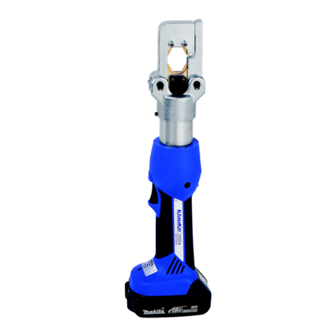
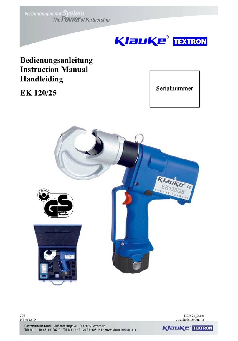
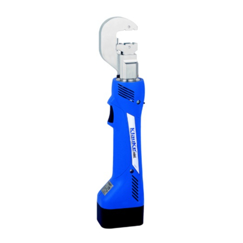
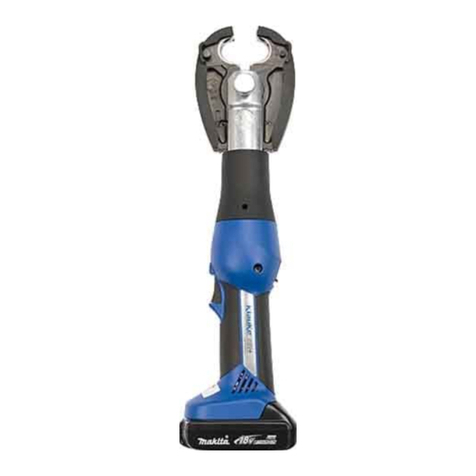
Klauke Ultra Plus EK 120 U-L User manual

EK 120 U-L
D Bedienungsanleitung
GB Instruction Manual
F Mode d´emploi
RUS Инструкция по
эксплуатации
Anzahl der Seiten: YY
HE.13447 © 11/2009 TE-2
Verbindungen mit System
The Power of Partnership
Gustav Klauke GmbH • Auf dem Knapp 46 • D-42855 Remscheid
Telefon ++49 +2191-907-0 • Telefax ++49 +2191-907-141 • www.klauke.textron.com
Serialnummer

EK 120 U-L
I
Bedienungsanleitung/Instruction Manual
HE.13447 © 11/2009
5
4
3
BL1830 (RAL2) 2
optional:
NG2
1
98 10
Bild/pic./fig. 1 (siehe/see Tab. 3)
6
7
HE.15333
2K

EK 120 U-L
II
Bedienungsanleitung/Instruction Manual
5304711CV142 batch# e.g. 304711
datecode e.g. „-cv“ for year 2009, month July
consecutive# e.g. „142“ for the 142nd tool
datecode
Year Code Month Code Month Code
2007 A Jan. N July V
2008 B Feb. P Aug. W
2009 C Mar. Q Sept. X
2010 D Apr. R Oct. Y
2011 E May S Nov. Z
2012 F June T Dec. 1
1 2 3 4
D-42855
Remscheid
5
Bild/pic./fig. 3 Bild/pic./fig. 4
(BL1830) 22 min.
RAL2
10 - 40°C
CLICK
Bild/pic./fig. 5 Bild/pic./fig. 7 Bild/pic./fig. 9Bild/pic./fig. 6 Bild/pic./fig. 8
Bild/pic./fig. 10
Li-ion
Bild/pic./fig. 11
®
#884676B996
#884598C990
Bild/pic./fig. 12
1. 2.3.
1. 2.3.
HE.13447 © 11/2009
HE.13428
HE.13430
EK 120 U-L
Nennspannung (Voltage): 18V DC
Preßkraft (Force): 120 kN
HE.13446
Bild/pic./fig. 2

EK 120 U-L
III
Bedienungsanleitung/Instruction Manual
Bild/pic./fig. 14
Bild/pic./fig. 15 Bild/pic./fig. 16
CLICK
CLICK
Bild/pic./fig. 13
on / off
PRESS
PRESS
HE.13447 © 11/2009

EK 120 U-L
IV
Bedienungsanleitung/Instruction Manual
1st ,2nd ,3rd ... crimp
PRESS
PRESS
PRESS
PRESS
Automatic Retraction Stopp
AUTO-
last crimp
0,5 sec.
max.
Bild/pic./fig. 17
PRESS
PRES
S
PRESS
PRES
S
PRESS
350°
1.
2.
HE.13447 © 11/2009

EK 120 U-L
V
Bedienungsanleitung/Instruction Manual
Bild/pic./fig. 21
OIL
1.
2.
3.
3
.
Bild/pic./fig. 19
Bild/pic./fig. 20
Bild/pic./fig. 18
OIL
OIL
OIL
OIL
HE.13447 © 11/2009

EK 120 U-L
VI
Bedienungsanleitung/Instruction Manual
D GB F RUS
Tab. 1
Wann/When
Когда это происходит
Warum/Why
Причина
20 sec
nach Arbeitsvorgang
after working cycle
après opération de travail
после цикла опрессовки
2 x
nach Einsetzen des Akkus
after inserting the battery
après mise en place de l’accumulateur
при установке аккумулятора
Selbsttest
Self check
autocontrôle
Самодиагностика инструмента
20 sec/2Hz
nach Arbeitsvorgang
after working cycle
après opération de travail
после цикла опрессовки
20 sec/5Hz
während der Übertemperatur
while exceeding the temp. limit
pendant surchauffe
при высокой температуре внутри корпуса
Werkzeug zu heiß
Unit too hot
outil surchauffé
Перегрев инструмента
20 sec
20 sec/2Hz
nach Arbeitsvorgang
after working cycle
après opération de travail
после цикла опрессовки
+
1 x
nach Arbeitsvorgang
after working cycle
après opération de travail
после цикла опрессовки
Fehler: der notwendige Pressdruck wurde nicht erreicht.
Es handelt sich um eine manuelle Unterbrechung der
Pressung bei stehendem Motor.
Error: the required pressure has not been reached. The
operator has interrupted the pressing cycle manually
while the motor was not running.
ERREUR: Pression necessaire pas atteinte. Il s‘agît
d‘une interruption manuelle de la sertissage au moteur
arrêté.
Ошибка: не было достигнуто требуемое усилие
опрессовки или оператор прервал процесс
опрессовки вручную, когда двигатель остановился.
3 x 3 x
nach Arbeitsvorgang
after working cycle
après opération de travail
после цикла опрессовки
Schwerwiegender Fehler: Pressdruck wurde bei laufen-
dem Motor nicht erreicht.
Serious Error: The pressure has not been reached while
the motor was running.
ERREUR GRAVE: Pression pas atteinte au moteur
courant.
Серьезная ошибка: не было достигнуто требуемое
усилие опрессовки во время работы двигателя
HE.13447 © 11/2009

EK 120 U-L
VII
Bedienungsanleitung/Instruction Manual
Tab. 2 (siehe Bild/see pic. 1, 6)
geeignet für
suitable for
Verb.
material
Connection
material
Pressbereich
mm²
Crimping
range mm²
Press-
form
Crimping
mold
Kennzeichnung
Marking
Rohrkabelschuhe und Verbinder - Cu (gelb chromatiert, Pressbreite 5 mm)
Copper tubular cable lugs and connectors - Cu (chrome plated, crimping width 5 mm)
außen
outside
Preßprofil
Profile
Rohrkabelschuhe und Verbinder „Normalausführung“, Rohrkabel-
schuhe für Schaltgeräteanschlüsse
Tubular cable lugs and connectors, „standard type“, tubular cable
lugs for switchgear connections
16 - 400 Cu,Cu, QS QS
Isolierte Rohrkabelschuhe und Verbinder, Normalausführung
Insulated cable lugs and compression joints, „standard type“ 10 - 150 IS, QS QS
Rohrkabelschuhe und Verbinder für feindrähtige Leiter
Tubular cable lugs and connectors for fine stranded conductors 16 - 150 F, QS QS
Presskabelschuhe und Verbinder nach DIN - Cu
Compression cable lugs and connectors to DIN, copper
Presskabelschuhe und Verbinder nach DIN - Cu
Copper compression cable lugs and connectors to DIN 16 - 300 Cu, QS Kennzahl
Doppelpresskabelschuhe
Double compression cable lugs 2 x 50 - 2 x 95 DP, QS QS
Quetschkabelschuhe, Verbinder und Stiftkabelschuhe nach DIN - Cu
Solderless terminals, connectors and pin terminals to DIN, copper
Quetschkabelschuhe (DIN 46234), Verbinder und
Stiftkabelschuhe (DIN 46230) nach DIN - Cu
Solderless terminals (DIN 46234), connectors and
pin terminals (DIN 46230) acc. to DIN
16 - 150 Cu, QS,
DIN 46234 QS
Isolierte Quetschkabelschuhe
Insulated solderless terminals 10 - 95 ISQ, QS QS
Hülsen für verdichtete Leiter und Sektorleiter - Cu
Sleeves for compacted conductors and sector shaped conductors, copper
Runddrückeinsätze für Al- und Cu-Sektorleiter
Pre-rounding dies for sector-shaped Al and Cu conductors 10sm - 300sm RU, QS, sm,
QS, sm --
Presskabelschuhe und Verbinder nach DIN - Al
Compression cable lugs and connectors to DIN, aluminium
Presskabelschuhe und Verbinder nach DIN - Al
Aluminium compression cable lugs and connectors to DIN - Al 10 - 240
Al, QS Kennzahl
Pressverbinder für zugfeste Verbindungen von Aldrey-Seilen nach
DIN EN 50182, Al-Leiter DIN EN 50182, 120-185 mm²
Compression joints for full-tension connections of Aldrey conductors
acc. to DIN EN 50182, Al-conductors DIN EN 50182, 120-185 mm²
25 - 185
Pressverbinder nach DIN 48085, Teil 3 für Al-Seile DIN EN 50182
Compression joints to DIN 48085, part 3 for Al-cables DIN EN 50182 25 / 4 - 120 / 20
Presskabelschuhe und Verbinder - Al/Cu
Compression cable lugs and connectors, Al/Cu
Presskabelschuhe und Verbinder - Al/Cu
Compression cable lugs and connectors - Al/Cu 10 - 240
Klemmen und Schraubverbinder
Clamps and screw connectors
Abzweigklemmen C-Form
C-clamps 10 - 70
C, QS --
Abzweigklemmen H-Form
H-clamps 70 - 120
Aderendhülsen
Cable end-sleeves
Aderendhülsen
Cable end-sleeves 25 - 240 AE, QS --
Aderendhülsen Trapez-Sonderform für ausgedünnte
(„verdichtete“) feindrähtige Leiter
Cable end-sleeves special trapezoid crimp for
„compacted“ fine stranded conductors
25 - 240
QS = Querschnitt/Cross-section; IS = isolierte Rohrkabelschuhe/ pre-insulated tubular cable lugs;
F = feindrähtige Leiter/ compacted fine str. conductors; ISQ = isolierte Quetschkabelschuhe/ pre-insulated tubular cable lugs;
RU = Runddrückeinsätze/ pre-rounding dies; sm = Sektorleiter mehrdrähtig/ multistranded conductors; AE = Aderendhülsen/ wire ferrules
Bitte beachten Sie bei der Verpressung von Verbindern die Einschränkungen im technischen Anhang unseres Kataloges!
Please observe the restrictions in the technical index of our catalogue when crimping connectors!
HE.13447 © 11/2009

Bedienungsanleitung
EK 120 U-L
1
D
Inhaltsangabe
1 Einleitung
2 Gewährleistung
3 Beschreibung des elektro-hydraulischen
Presswerkzeuges
3.1 Beschreibung der Komponenten
3.2 Kurzbeschreibung der wesentlichen Leistungs-
merkmale des Gerätes
3.3 Beschreibung der Leuchtdiodenanzeige
4 Hinweise zum bestimmungsgemäßen Gebrauch
4.1 Bedienung des Gerätes
4.2 Erläuterung des Anwendungsbereiches
4.3 Verarbeitungshinweise
4.4 Wartungshinweise
5. Verhalten bei Störungen am Werkzeug
6. Technische Daten
7. Außerbetriebnahme/Entsorgung
Symbole
Sicherheitstechnische Hinweise
Bitte unbedingt beachten, um Personen- und
Umweltschäden zu vermeiden.
Anwendungstechnische Hinweise
Bitte unbedingt beachten, um Schäden am
Werkzeug zu vermeiden.
1. Einleitung
Vor Inbetriebnahme Ihres Presswerkzeu-
ges lesen Sie sich die Bedienungsanlei-
tung sorgfältig durch.
Benutzen Sie dieses Werkzeug ausschließlich für den be-
stimmungsgemäßen Gebrauch.
Das Presswerkzeug darf nur durch eine elektrotechnisch
unterwiesene Person bedient werden. Das Mindestalter
beträgt 16 Jahre.
Diese Bedienungsanleitung ist während der gesamten
Lebensdauer des Werkzeuges mitzuführen.
Der Betreiber muss
• dem Bediener die Betriebsanleitung zugänglich ma-
chen und
• sich vergewissern, daß der Bediener sie gelesen und
verstanden hat.
2. Garantie
Die Garantie beträgt bei bestimmungsgemäßer
Verwendung und unter Einhaltung der War-
tungsintervalle 24 Monate ab Lieferdatum. Aus-
geschlossen von der Garantie sind Verschleiß-
teile, die sich aus dem bestimmungsgemäßen
Gebrauch ergeben. Wir behalten uns ferner
das Recht vor, das Produkt nachzuarbeiten.
3. Beschreibung des elektro-hydrauli-
schen Pressgerätes
3.1 Beschreibung der Komponenten
Das elektro-hydraulische Werkzeug ist handgeführt und
besteht aus folg. Komponenten:
Tabelle 3 (siehe Bild 1)
Pos. Bezeichnung Funktion
1 Leuchtdioden-
anzeige (rot)
~ zum Feststellen des Ladezu-
standes, eines Gerätefehlers
und zur Wartungsanzeige.
2 Akku wiederaufladbarer
3Ah Li-Ion Akku (RAL2)
Optional:
Netzgerät NG2
3 Bedienungs-
schalter
Auslösung des Pressvorgangs
4 Rückstelltaste Taste zum Öffnen der Pressein-
sätze im Fehler-, bzw. Notfall
5 Arbeitsplatz-
beleuchtung
zur Ausleuchtung des
Arbeitsumfeldes
6 Presskopf 120kN U-Presskopf
7 Einsatzhalter seitlich herausnehmbarer Block
zur Aufnahme der Einsätze
8 Presseinsätze Halbschalenwerkzeugeinsätze
mit unterschiedlichen Presspro-
filen
9 Ring Öse zum Sichern des Werk-
zeuges und/oder zu Montage-
zwecken
10 Gehäuse Ergonomisch geformtes
2K-Kunststoffgehäuse
3.2 Kurzbeschreibung der wesentlichen
Leistungsmerkmale
Das Presswerkzeug besitzt einen automatischen
Rücklauf, der den Kolben nach Erreichen des max.
Betriebsüberdruckes automatisch in die Ausgangs-
lage zurückfährt.
Ein manueller Rücklauf ermöglicht dem Bediener
im Falle einer Fehlpressung den Kolben in die Aus-
gangslage zurückzufahren.
Eine automatische Rücklaufunterbrechung stoppt
den Rücklauf querschnittsabhängig, sodaß Zeit und
energiesparend gearbeitet werden kann.
Das Presswerkzeug ist mit einem Nachlaufstopp
ausgerüstet, der den Vorschub nach Loslassen des
Bedienungsschalters sofort stoppt.
Das Presswerkzeug ist mit einer Doppelkolbenpum-
pe ausgestattet, die durch einen schnellen Vorschub
bis zur Berührung des Werkstücks gekennzeichnet
ist.
Der Presskopf ist stufenlos 350° um die Längsach-
se drehbar. Dieses ermöglicht Montagen auch an
sehr schlecht zugänglichen Stellen.
HE.13447 © 11/2009

Bedienungsanleitung
EK 120 U-L
2
D
Das Presswerkzeug ist mit einer Mikroprozessor-
Steuerung ausgestattet, die z.B. den Motor nach
vollendetem Pressvorgang abschaltet, Service-In-
tervalle anzeigt, den Ladezustand des Akkus angibt
und eine Fehlerdiagnose durchführt, bzw. unter-
schiedliche akustische und optische Warnsignale
bei einer Fehlanwendung aussendet.
Das Gerät verfügt über einen integrierten Druck-
sensor, der bei jedem Pressvorgang automatisch
den erreichten Pressdruck ermittelt und speichert.
Bei Abweichungen vom festgelegten Arbeitsdruck
ertönt ein akustisches Signal und eine rote LED eu-
chtet auf (Tab. 1).
Eine eingebaute weiße LED beleuchtet den Arbeits-
bereich nach Aktivierung des Bedienungsschalters
und schaltet sich nach 10 s wieder aus. Dieses
Merkmal läßt sich auch ausschalten.
Es kann mittels eines USB Adapters (Zubehör) nach
Arbeitsende ein Protokoll über die ordungsgemäße
Funktion des Presswerkzeugs über den PC ausge-
druckt werden.
Das kompakte ergonomische geformte Gehäuse
besteht aus 2 Komponenten. Der Griffbereich ist
durch seine Gummierung besonders rutschfest und
zusammen mit dem schwerpunktoptimierten Ge-
häuse liegt das Werkzeug besonders gut in der
Hand und unterstützt so ermüdungsfreies Arbeiten.
Alle Funktionen unserer Geräte können über einen
Bedienknopf gesteuert werden. Dadurch bekom-
men wir eine einfache Handhabung und besseren
Halt als bei einer Zweiknopfbedienung.
Durch die Li-Ionen Batterien, die weder Memory
Effekt noch Selbstentladung kennen, hat der Bedie-
ner auch nach langen Arbeitspausen immer ein ein-
satzbereites Gerät. Dazu kommt noch ein geringe-
res Leistungsgewicht mit 50% mehr Kapazität und
kurzen Ladezeiten im Vergleich zu NiMH Akkus.
Das eingesetzte Öl ist besonders umweltfreundlich
und ist mit dem Blauen Engel ausgezeichnet. Fer-
ner ist das Öl auch für sehr niedrige Temperaturen
geeignet und hat exzellente Schmiereigenschaften,
sodaß unsere Geräte quasi Wartungsfrei sind.
3.3 Beschreibung der Werkzeugindikation
Siehe Tabelle 1.
Es sollte vor Arbeitsbeginn der Ladezustand des Akkus
(Bild 1.2) überprüft worden sein. Ein niedriger Ladezu-
stand kann beispielsweise an der Leuchtdiode (Bild 1.1)
durch ein 20 s’iges Aufleuchten am Ende einer Pressung
erkannt werden.
4. Hinweise zum bestimmungsgemä-
ßen Gebrauch
Vor Arbeitsbeginn sind alle aktiven, d.h. stromführenden
Teile im Arbeitsumfeld des Monteurs freizuschalten. Ist
dieses nicht möglich sind entsprechende Schutzvorkeh-
rungen für das Arbeiten in der Nähe von unter Spannung
stehenden Teilen zu treffen (siehe z.B. DIN EN 50110).
Halten Sie Ihren Arbeitsbereich sauber und aufgeräumt.
Verwenden Sie dieses Werkzeug nicht wenn Sie müde
sind oder unter Einfluß von Drogen, Alkohol oder Medi-
kamenten stehen.
2K
4.1 Bedienung des Werkzeuges
Ablauf: siehe Bilder vorne
Bei Tiefnutpressungen wird der Einsatzhalter seitlich aus
dem Preßkopf entfernt und statt dessen der Tiefnutkäfig
eingeschoben. Auf der gegenüberliegenden Seite muß
der dazugehörige Tiefnutdorn in den Adapter eingesetzt
werden (Bild 16).
4.2 Erläuterung des Anwendungsbereiches
Das Pressgerät verfügt über eine große Anzahl verschie-
dener Presseinsätze.
Achtung
Es dürfen nur die bestimmungsmäßigen Ver-
bindungsmaterialien (siehe Tab. 2) verarbeitet
werden.
Sollten andere Verbindungsmaterialien verpresst werden
müssen, ist eine Rücksprache mit dem Werk zwingend
erforderlich.
Die Tiefnutpressung wird gemäß der Französischen Norm
C 33-090-4 ausgeführt.
Achtung
EsdürfenkeineunterSpannungstehenden
Teile verpresst werden.
Bei diesem Gerät handelt es sich um ein handgeführtes
Gerät, das nicht eingespannt werden darf. Es darf nicht
für den stationären Einsatz verwendet werden.
Das Gerät ist nicht für den Dauerbetrieb geeignet. Es
muss nach ca. 40 Presszyklen hintereinander eine Pause
von ca. 15 min eingelegt werden um das Gerät abzuküh-
len.
Achtung
Bei zu intensivem Gebrauch kann es durch Er-
hitzung zu Schäden am Gerät kommen.
Achtung
Beim Betrieb von Elektromotoren kann es zur
Funkenbildung kommen, durch die feuergefähr-
liche oder explosive Stoffe in Brand gesetzt wer-
den können.
Achtung
Das elektrohydraulische Pressgerät darf nicht
bei starkem Regen oder unter Wasser einge-
setzt werden.
4.3 Verarbeitungshinweise
Bitte beachten Sie unbedingt die in unserem Katalog an-
geführten Montagehinweise.
Achtung
Es dürfen auch bei gleicher Kennzahl nur die für
das Material vorgesehenen Presseinsätze ver-
wendet werden.
HE.13447 © 11/2009
Bedienungsanleitung
EK 120 U-L
3
D
4.4 Wartungshinweise
Die zuverlässige Funktion des Presswerkzeuges ist ab-
hängig von einer pfleglichen Behandlung. Diese stellt
eine wichtige Voraussetzung dar, um dauerhaft sichere
Verbindungen zu schaffen. Um diese sicherzustellen,
bedarf das Werkzeug einer regelmäßigen Wartung und
Pflege. Wir bitten folgendes zu beachten:
1.Das elektro-hydraulische Presswerkzeug ist nach je-
dem Gebrauch zu reinigen und ein trockener Zustand
ist vor Einlagerung sicherzustellen.
2.Um eine einwandfreie Funktion des Werkzeuges si-
cherzustellen und möglichen Funktionsstörungen vor-
zubeugen, sollte das Presswerkzeug nach Ablauf eines
jeden Jahres oder nach 10.000 Verpressungen zur
Wartung oder zum Service eingeschickt werden.
3.Sowohl Akku als auch Ladegerät müssen vor Feuchtig-
keit und vor Fremdkörpern geschützt werden.
4.Die Bolzenverbindungen, Funktionselemente und Füh-
rung sind leicht einzuölen.
Die werkseitige Wartung des Werkzeuges (siehe ASC)
besteht aus Demontage, Reinigung, Austausch evtl. ver-
schlissener Teile, Montage und Endkontrolle.
Im Rahmen des bestimmungsgemäßen Gebrauchs dür-
fen vom Kunden nur die Presseinsätze (Bild 1.8) gewech-
selt werden.
Achtung
Werkzeug nicht öffnen! Bei beschädigter Versie-
gelung entfällt der Garantieanspruch.
5. Verhalten bei Störungen am
Werkzeug
a.) Regelmässiges Blinken/Leuchten der roten Leucht-
diode (Bild 1.1) oder Ertönen eines akustischen
Warnsignals.
siehe Tabelle 1. Sollte sich die Störung nicht ab-
stellen lassen, ist das Werkzeug an das nächst
gelegene Service Center (ASC) zu schicken.
b.) Das Presswerkzeug verliert Öl.
Das Werkzeug ist einzuschicken. Nicht öffnen
und die Geräteversiegelung nicht entfernen.
c.) Die rote LED (Bild 1.1) blinkt 3x und gleich
zeitig ertönen 3 Warnsignale (siehe Tab. 1).
Schwerer Fehler! Wenn dieser Fehler wiederholt
auftritt ist das Werkzeug einzuschicken. Gerät
nicht öffnen und die Geräteversiegelung nicht
entfernen. Bei einmaligem Auftreten dieses Feh-
lers muss das Verbindungsmaterial nachgepresst
werden.
Achtung
Geräteversiegelung nicht beschädigen! Bei Be-
schädigung der Geräteversiegelung erlischt der
Garantieanspruch.
6. Technische Daten
Gewicht
(inklusive Akku):
ca. 6 kg
Antriebskraft: ca. 120 kN
Hub 20 mm
Akkuspannung: 18 V
Akkukapazität: 3 Ah (RAL2/BL1830)
Akku-Ladezeit: 22 min. (RAL2/BL1830)
Presszeit: 5 s bis 8 s (abhängig vom
Verbinderquerschnitt)
Pressungen
pro Akku:
ca. 115 Pressungen
(Cu 150 mm² DIN 46235)
Hydrauliköl: Rivolta S.B.H. 11
Umgebungs-
temperatur:
-20°C bis +40°C
Schalldruckpegel: 70 dB (A) in 1m Abstand
Vibrationen: < 2,5 m/s²
(gewichteter Effektivwert der
Beschleunigung)
7. Außerbetriebnahme/Entsorgung
Dieses Werkzeug fällt in den Geltungsbereich der Eu-
ropäischen WEEE (2002/96/EG) und RoHS Richtlinien
(2002/95/EG), die in Deutschland durch das Elektro- und
Elektronikgerätegesetz (ElektroG) umgesetzt wurden.
Informationen dazu finden Sie auf unserer Homepage
www.klauke.com unter WEEE & RoHS.
Akkus müssen unter Berücksichtigung der Batterieveror-
dung speziell (getrennt) entsorgt werden.
Achtung
Das Werkzeug darf nicht im Restmüll entsorgt
werden. Die Entsorgung muss durch den Ent-
sorgungspartner der Fa. Klauke vornehmen
werden.
Kontaktadresse: [email protected]extron.com
Anmerkung
Diese Bedienungsanleitung kann jederzeit kos-
tenlos unter der Bestell-Nr. HE.13447 nachbe-
stellt werden.
HE.13447 © 11/2009

EK 120 U-L
1
Instruction Manual
GB
Index
1. Introduction
2. Warranty
3. Description of the electric-hydraulic
crimping tool
3.1 Description of the components
3.2 Brief description of the important features of
the unit
3.3 Description of the light diode display
4. Remarks in respect of the determined use
4.1 Operation of the unit
4.2 Explanation of the application range
4.3 Mounting instructions
4.4 Service and Maintenance instructions
5. Troubleshooting
6. Technical data
7. Putting out of operation/waste disposal
Symbols
Safety warnings
Please do not disregard these instructions in or-
der to avoid human injuries and environmental
damages.
Operational warnings
Please do not disregard them to avoid dama-
ging the pump unit.
1. Introduction
Before starting to use the tool please read
the instruction manual carefully.
Use this tool exclusively for its determined use.
Mounting and assembly of connecting material with the
help of this tool must only be performed by specially trai-
ned personnel. The minimum age is 16 years.
This instruction manual has to be carried along during the
entire life span of that tool.
The operator has
• to guarantee the availability of the instruction manual
for the user and
• to make sure, that the user has read and understood
the instruction manual.
2. Warranty
If the tool is operated according to its intended
use and the regular maintenance services are
observed our warranty is 24 months from the
time of delivery. Worn-out parts resulting from
its intended use are excluded. We reserve the
right to rework the tool in case of a justified war-
ranty claim.
3. Description of the electric-
hydraulic crimping tool
3.1 Description of the components
The electric-hydraulic crimping unit is a hand held tool
and consists of the following components:
Table 3 (see Picture 1)
Pos. Description Function
1 Light diode
display (red)
Indicator for battery charge
control, tool functions and
faults
2 Battery
cartridge
rechargeable
3Ah Li-Ion battery (RAL2)
Optional:
mains adapter NG2
3 Trigger switch to start working cycle
4 Retract button button to retract the piston in
case of error or emergency
5 Light LED to illuminate the working area
6 Crimping head U-shape crimping head for
120kN
7 Die holder opposite support to accommo-
date the dies
8 Dies interchangeable crimping dies
9 Ring Loop to secure the tool and/or
for assembly purposes
10 Housing ergonomically formed plastic
housing in a 2-Component
design for perfect handling
3.2 Brief description of the important fea-
tures of the unit
The hydraulic unit incorporates an automatic retrac-
tion which returns the piston into its starting position
when the maximum operating pressure is reached.
A manual retraction allows the user to return the pis-
ton into the starting position in case having selected
the wrong cable.
An automatic retraction stops the retraction of the
piston depending on the connector size which sa-
ves time and energy.
The unit is equipped with a special brake which
stops the forward motion of the piston/dies when
the trigger is released.
The unit is equipped with a double piston pump
which is characterised by a rapid approach of the
dies towards the connector and a slow crimping
motion.
The crimping head can be smoothly turned by 350°
around the longitudinal axis in order to gain better
access to tight corners and other difficult working
areas.
The tool is equipped with a microprocessor which
shuts off the motor automatically after the crimp is
completed, indicates service intervals and low bat-
tery charges and performs internal checks sending
out acoustical and optical warning signals in case of
a detected fault.
HE.13447 © 11/2009

EK 120 U-L
2
Instruction Manual
GB
The new tools feature an integrated pressure sen-
sor which automatically identifies the achieved crim-
ping force during every crimping operation. If a de-
viation from the set operation pressure is identified,
an acoustic signal sounds and a red display flashes
(tab. 1).
A white LED illuminates the working space after ac-
tivating the trigger. It automatically switches off 10
sec. after releasing the trigger. This feature can be
deactivated.
Through an optional USB adapter a report can be
generated at the end of a working session at a PC
documenting the proper function of the tool.
The compact ergonomically formed design consists
of 2 components. The grip area is rubber coated
and therefore slip resistent. The housing design is
optimized in respect of the center of gravity which
improves the handling and supports fatique-proof
working.
All tool functions can be controlled by one trigger.
This results in an easy handling and a better grip
compared to a two button operation.
Li-Ion batteries do neither have a memory effect nor
self discharge. Even after long periods of non ope-
ration the tool is always ready to operate. In addition
we see a lower power weight ratio with 50% more
capacity and shorter charging cycles compared to
NiMH batteries.
The oil used in our tool is particularly environmen-
tally friendly and and has been rewarded „The Blue
Angel“. The oil is also suitable for low temperatures
and has excellent lubrication characteristics.
3.3 Description of the tool indication
See Tab. 1.
Prior to operating the unit the charging level of the battery
(pic. 1.2) should have been tested2. A low charging level
can be detected by the flashing of the LED (pic. 1.1) for
20 s at the end of a crimping cycle.
2K
4. Remarks in respect of the determi-
ned use
Before starting any work on electrical appliances it must
be safeguarded that there are no live parts in the imme-
diate assembly area of the user. If this not possible spe-
cial precaution measures (e.g. acc. to EN 50110-1) for working
near live parts must be provided.
Keep your working area clean and tidy. Do not use this
tool when you are tired, on drugs, had alcohol or if you
are medicated.
4.1 Operation of the unit
Cycle: see pictures in front
When performing deep indent crimps the die-holder must
be replaced against the connector cage of the deep in-
dent crimp set. On the opposite side the indenter must be
set into the adapter (pic. 16).
4.2 Explanation of the application range
The electric hydraulic unit can be operated with a large
number of various crimping dies.
Attention
Do only crimp those connecting materials men-
tioned in Tab. 2.
If different conducting materials have to be crimped, ple-
ase contact the manufacturer.
The deep indent crimping is performed according to the
French Standard C 33-090-4.
Attention
Do not crimp on live cables or conduc-
tors
The unit is a hand held tool and it is not supposed to be
restrained in a vise. It is not allowed to use the tool in a
stationary application.
The tool is not designed for continued operations. After
a sequence of approximately 40 completed cycles you
have to make a break of 15 min. to give the tool time to
cool down.
Attention
Too intensive use can cause heat damages for
the tool
Attention
During the operation of electric engines sparks
can occur which might ignite highly inflammab-
le or explosive liquids and materials
Attention
Electric-hydraulic tools should not be operated
in pouring rain or under water.
4.3 Mounting instructions
Please read the assembly instructions in our general ca-
talogue.
Attention
Even if the code number is identical only those
dies should be used which are suitable for the
material.
HE.13447 © 11/2009
EK 120 U-L
3
Instruction Manual
GB
4.4 Service and maintenance instruction
The reliable performance of the tool is dependent on ca-
reful treatment and service. This represents an important
condition to safeguard a lasting connection. To safeguard
this the tool have to be maintained and serviced regular-
ly
We would like to draw your attention to the following
points:
1.The electric-hydraulic pressing unit have to be cleaned
and dried after each use before being put into the trans-
portation case.
2.In order to guaranty a proper function of the machine
the pressing tool should be returned to the manufac-
turer or one of our Authorized Service Centers (ASC)
after the light diode display indicates Service or after
each year whatever comes first.
3.The battery as well as the charging unit must be protec-
ted against humidity and foreign objects.
4.The bolt joins, function elements and guides must be
oiled regularly in small amounts.
In order to avoid possible malfunctions we offer you a ma-
nufacturer service consisting of disassembly, cleaning,
exchange of possibly worn out parts assembly and final
control (see ASC).
Within the determined use of the tool only the dies
(pic. 1.8) are permitted to be changed by the customers.
Attention
Do not damage the seals of the tool. If the seals
are damaged the warranty is invalidated.
5. Troubleshooting
a.) Constant flashing/indicating of the red LED (pic 1.1)
or the occurence of an acoustical warning signal.
see table 1. If the failure can not be solved return the
tool to the nearest service center (ASC).
b.) The tool loses oil.
Return the unit to the manufacturer. Do not open it and
damage the seal of the tool.
c.) The red LED flashes 3x and simultaneously 3 acou-
stic warning signals occure (see table 1).
Serious fault! If this fault occures repeatedly return the
unit to an Autorized Service Center (ASC). Do not open
it and damage the seal of the tool.
In case of a one time occurence the connector has to
be pressed a second time.
6. Technical Data
Weight
(incl. battery):
6,32 kg
Crimping force: approx. 120 kN
Stroke 20 mm
Battery voltage: 18 V
Battery capacity 3 Ah (RAL2/BL1830)
Charging time: 22 min. (RAL2/BL1830)
Crimping time: approx. 5 s to 8 s
(depending on the connector size)
Crimps
per battery:
approx. 115 crimps
(Cu 150 mm² DIN 46235)
Hydraulic oil: Rivolta S.B.H. 11
Environmental
temperature:
-20°C to +40°C
Sound level: 70 dB (A) in 1m distance
Vibrations: < 2,5 m/s²
Dimensions: See Picture 2
7. Putting out of operation/waste dis-
posal
This unit is subjected to the scope of the European WEEE
(2002/96/EG) and RoHS (2002/95/EEC) directives.
Information about this can be found on our home page
www.Klauke.com under ‘WEEE & RoHS’.
Battery cartridges (page I, pic. 1, 3) must be specially dis-
posed of according to the EEC Battery Guideline.
Attention
Do not dispose of the unit in your residential
waste. Klauke has no legal obligation to take
care of their WEEE outside Germany unless the
product has been shipped and invoiced from
inside your country by Klauke. Please contact
your distributer to find out more how to get your
tool recycled environmentally friendly.
Attention
Additional instruction manuals are available
free of charge. The part # is HE.13447.
HE.13447 © 11/2009

EK 120 U-L
1
F
Mode d’emploi
Sommaire
1 Introduction
2 Garantie
3 Description de la sertisseuse électro-
hydraulique
3.1 Description des composants
3.2 Description succincte des principales
caractéristiques de l‘appareil
3.3 Description de l‘affichage LED
4 Instructions pour une utilisation conforme
4.1 Utilisation de l‘appareil
4.2 Description du domaine d‘application
4.3 Instructions pour l‘utilisation
4.4 Instructions pour la maintenance
5. Marche à suivre en cas de panne de la
sertisseuse
6. Caractéristiques techniques
7. Mise hors service/Mise au rebut
Symboles
Instructions techniques de sécurité,
à respecter impérativement, pour la sécurité des
personnes et la protection de l‘environnement.
Instructions techniques d‘utilisation,
à respecter impérativement, pour éviter des dom-
mages à l‘appareil.
1. Introduction
Lire attentivement le mode d‘emploi avant la mise en ser-
vice de votre sertisseuse.
N‘utilisez cet appareil qu‘exclusivement pour l‘usage pré-
vu, en respectant les instructions relatives à la sécurité et
à la prévention des accidents du travail.
N‘utilisez cet appareil qu‘exclusivement pour l‘usage pré-
vu.
Ce mode d‘emploi doit accompagner l‘appareil pendant
toute sa durée d‘utilisation.
L‘exploitant doit
• mettre le mode d‘emploi à la disposition de l‘utilisateur et
• s‘assurer que celui-ci ait lu et bien compris son contenu.
2. Garantie
La garantie s’élève à 24 mois date de la livrai-
son à condition d’une utilisation de l’outil exclu-
sivement pour son usage déterminé et
d’observation des intervalles des maintenance.
Sauf pièces de rechanges qui résultent d’un
usage déterminé. Nous réservons le droit de
récupérer le produit.
3. Description de la sertisseuse
électro-hydraulique
3.1 Description des composants
La sertisseuse électro-hydraulique type EK120U-plus est
un appareil manuel qui se compose des éléments su-
ivants
Tableau 3 (voir figure 1)
Pos. Désignation Fonction
1Afficheur LED
(rouge)
Afficheur de contrôle de l’état
de charge et autres fonctions
de l’appareil
2 Accumulateur Accumulateur rechargeable
3Ah Li-Ion (RAL2/BL1830)
Équipement spécial:
Bloc d’alimentation NG2
3 Commutateur
de marche
Déclenchement du sertissage
4 Touche
de retour
Retour du piston en position
initiale en cas de défaut ou
d’urgence
5Afficheur LED
(blanche)
Pour l’éclairage du local de
travail
6 Tête
de sertissage
Tête de sertissage
en U - 120kN
7 Porte
mâtrices
support opposé à accueillir les
matrices
8 Matrices
de sertissage
Matrices permettant d’effectuer
le sertissage (interchangeables
en fonction de la section et
du type de produit à sertir
9 Bague de
sécurité
Bague de sécurité de l‘appareil
et/ou bague destinée au monta-
ge des accessoires
10 Corps
de l’appareil
2K-Corps de la sertisseuse de
forme ergonomique avec
cache réservoir
3.2 Description succincte des principales
caractéristiques de l’appareil
L’appareil possède une fonction de retour automa-
tique, qui ramène automatiquement la matrice en
position initiale après que les sertissage ait atteint
la pression maxi requise.
Une rétractation manuel permet à l‘utilisateur de re-
monter le piston dans la position de départ en cas
d‘une sertissage incorrecte.
Une interruption automatique de la rétraction arrête
la rétraction dependant de la section, permettant un
travail économisant de l‘energie et du temps.
L’appareil est équipé d’un dispositif d’arrêt immédiat
qui stoppe instantanément l’avance dès que le bou-
ton de sertissage est relâché.
L’appareil est équipé d’une pompe à piston double,
caractérisée par une vitesse d’approche rapide et
d’une course lente de sertissage.
Fonction d’évaluation par interface optique et adap-
tateur USB. (Équipement spéciale).
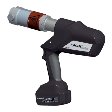
HE.13447 © 11/2009
EK 120 U-L
2
F
Mode d’emploi
À chaque cycle de sertissage, la pression atteinte
est déterminée au moyen d’un capteur de pressi-
on, puis comparée à la valeur minimale requise.
Un signal acoustique et optique paraît lorsque des
différences par rapport à la pression de travail dé-
terminée se produisent (Tab. 1).
La tête de sertissage peut être tournée de 330° en
continu autour de son axe. Ceci permet le sertissa-
ge dans des endroits difficilement accessibles.
La sertisseuse est équipé d’une commande à mi-
croprocesseur qui coupe le moteur lorsque le sertis-
sage est complètement terminé, qui indique la péri-
odicité de la maintenance, ainsi que l’état de charge
de l’accumulateur et qui effectue un diagnostic des
défauts.
LED blanche illumine le local de travail en action-
nant le commutateur de service et s’éteint après 10
s. Cette fonction peut être éliminée.
Le corps en plastique bi-matière avec insert souple
contribue à une sensation de prise agréable et sûre.
La position optimisée du centre de gravité permet
en complément un travail durable et sans fatigue.
Toutes fonctions de l’outil s’effectuent par moyen
d’une commande à bouton unique pour une manie-
ment aisée et un meilleur appui.
Accus lithium-ions 18V puissants avec une capaci-
té complémentaire de 50% et des délais de charge
extrêmement courts. Ces accumulateurs n’ont pas
d’effet mémoire et auto-décharge électrique.
Cet outil travaille avec huiles hydrauliques synthé-
tiques. Ces huiles sont facilement biodégradables
et ne présentent aucun danger pour l’eau.
3.3 Description de l’afficheur LED
Voir tableau 1
Contrôlez avant utilisation l‘état de charge de
l‘accumulateur. Un état de charge faible peut être recon-
nu lorsque la LED reste par exemple allumée pendant 20
secondes après un essai de sertissage.
4. Instructions pour une utilisation
conforme
Avant l’utilisation de la sertisseuse, s’assurer qu’aucun
composant actif sous tension n’est accessible. Si tel de-
vait être le cas, des précaution particulière devront être
prises (voir DIN EN 50110).
Gardez votre zone de travail propre et rangé. Ne pas uti-
liser cet outil lorsque vous êtes fatigué, sous l‘influence
des drogues,de l‘acool ou des médicaments.
4.1 Utilisation de l’appareil
Cycle: voir les photos en face
Lors de la sertissage à rainures profondes le support des
matrices doit être echangé par la cage à rainures profon-
des. À la côté opposée le mandrin correspondant doit
être mis dans l‘adapteur (fig. 16).
2K
Pour effectuer le sertissage par P.P.E (poinçonnage pro-
fond étagé, suivant la norme E.D.F HN68.S.90), il faut
monter d’abord le poinçon correspondant (0E - 1E - 2E
- 4E) sur le porte poinçon PP120 et monter le tout sur
le piston de la sertisseuse, puis retire le support matrice
SM120 (pos.3) et mettre en place une matrice avec som-
mier incorporé (MC0E - MC1E - MC2E MC4E - MJ0E -
MJ1E - MJ2E - MJ4E etc...)
4.2 Description du domaine d’application
La sertisseuse peut être utilisée dans un grand nombre
d’application de sertissage de raccords et cosses KLAU-
KE, ainsi que de tout type de raccords disponibles sur le
marché mondial (voir tableau 4).
Attention
Seuls les cosses et raccords mentionnés au Ta-
bleau 2 peuvent être sertis.
Si vous devez sertir d‘autres raccords, il est indispensab-
le de vous entretenir au préalable de ce problème avec
l‘usine.
Le sertissage à rainures profondes est effectué selon la
norme française C 33-090-4.
Attention
Ne jamais sertir des composants sous
tension.
Cet appareil est un appareil qui est tenu à la main et ne
doit être en aucun cas monté en fixe ni utilisé en fixe.
Vous ne devez pas l‘utiliser en fixe sans un dispositif spé-
cialement certifié.
L’appareil n’est pas destiné à une utilisation en continu.
Après environ 40 sertissages successifs, il est nécessaire
de marquer une courte pause d’au moins 15 minutes afin
que l’appareil puisse refroidir.
Attention
Une utilisation intensive peut provoquer des
dommages à l’appareil par suite de surchauffe.
Attention
Les moteurs électriques peuvent produire des
étincelles pouvant mettre le feu à des matières
explosives ou inflammables.
Attention
La sertisseuse ne doit pas être utilisée en cas de
forte pluie ou sous l’eau.
4.3 Instructions pour l’utilisation
Veiller à utiliser l’appareil les matrices adaptées au pro-
duit à sertir, et en cas de doute prendre contact avec le
fabricant.
Attention
Utiliser uniquement les matrices adaptées au
matériel à sertir.
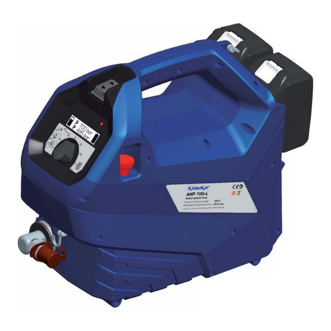
HE.13447 © 11/2009
EK 120 U-L
3
F
Mode d’emploi
Tableau 4
Référence Cosses et manchons
cuivre NFC 20-130 (mm²)
Raccords en C
(mm²)
Observations: matrices
couleur
empreinte
HNF 13/10 10 C6 bichromatage jaune hexagonale marquée 10
HNF 13/16 16 bichromatage jaune hexagonale marquée 16
HNF 13/25 25 C25 bichromatage jaune hexagonale marquée 25
HNF13/35 35 bichromatage jaune hexagonale marquée 35
HNF13/50 50 bichromatage jaune hexagonale marquée 50
HNF13/70 70 C16 bichromatage jaune hexagonale marquée 70
HNF13/95 95 bichromatage jaune hexagonale marquée 95
HNF13/120 120 bichromatage jaune hexagonale marquée 120
HNF13/150 150 C25-C35-C50 bichromatage jaune hexagonale marquée 150
HNF13/185 185 bichromatage jaune hexagonale marquée 185
HNF13/240 240 bichromatage jaune hexagonale marquée 240
HNF13/300 300 bichromatage jaune hexagonale marquée 300
Référence Cosses alu-cuivre indust.
à fût court (mm²)
Observations:
matrices couleur
empreinte
HE13/140 35 -50 bichromatage blanc hexagonale double 2x9mm
HE13/173 70-95-120 bichromatage blanc hexagonale double 2x9mm
HE13/235 150-185-240 bichromatage blanc hexagonale double 2x9mm
HE13/260 300 bichromatage blanc hexagonale double 2x9mm
Cosses alu-cuivre
Matrice
HN.68.S.90
Poinçon
Manchon aluminium
Matrice
HN.68.S.90
Poinçon
Sections
(mm²)
MC0E OE MJ0E 0E 16-25-35
MC1E 1E MJ1E 1E 50-70-95
MC2E 2E MJ2E 2E 120-150
MC4A 4E MJ4E 4E 185-240
HE.13447 © 11/2009

EK 120 U-L
4
F
Mode d’emploi
4.4 Instructions pour la maintenance
Effectuez soigneusement la maintenance de votre ap-
pareil pour lui assurer un fonctionnement sûr et satisfai-
sant. L’entretien est condition essentielle de l’obtention de
sertissages de qualité. Pour garantir ce résultat l’appareil
doit faire l’objet d’une maintenance et d’un entretien régu-
lier. Veuillez tenir compte des points suivants:
1. La sertisseuse doit être nettoyée après chaque utilisa-
tion et doit être remise dans un coffret sec.
2.Afin de garantir une fonction propre de la machine,
l‘outil de compression doit être retourné au fabricant
ou à l‘un de nos centres de service autorisés (ASC)
après l‘affichage diode indiquant service ou après
chaque année tout ce qui vient en premier.
3. L’accumulateur ainsi que le chargeur doivent égale-
ment être éloignés de toute humidité.
4.Les boulons de connexion, les éléments de la fonction
et les guides doivent être huilés régulièrement en peti-
tes quantités.
Afin d‘éviter d‘éventuels dysfonctionnements, nous
vous proposons un service constructeur composé de
démontage, nettoyage, échange de peut-être usés pièces
d‘assemblage et de contrôle final (voir ASC).
La seule opération autorisée au client dans le cadre d’une
utilisation de l’appareil conforme à sa destination est le
changement des mâchoires, des adaptateurs et des la-
mes.
Attention
Ne pas ouvrir l’appareil sous peine de perdre la
garantie
5. Marche à suivre en cas de panne
de la sertisseuse
a.) Signal lumineux régulier de LED rouge ou signal
d’avertissement acoustique (page I, figure 1.1).
Voir tableau 1. Si le dérangement ne peut pas
être arrêté retourner l’outil au prochain Centre
d’assistance (ASC).
b.) La sertisseuse pert de l‘huile.
Renvoyez l‘appareil à l‘atelier. Ne pas ouvrir
l‘appareil, ni retirer les scellés.
c.) 3 fois signal optique par moyen LED (page I, figu-
re 1.1) et 3 fois signal acoustique en même temps
(voir tableau 1).
Erreur grave! Au cas de répétition de cet erreur re-
tournez l’outil. Ne pas ouvrir l’outil et ne pas enlever
le sceau de garantie. Si cet erreur se produit seul
une fois l’utilisateur doit démonter le raccord ou ser-
tir le raccord encore une fois.
6. Caractéristiques techniques
Poids de l’appareil
complet:
environ 6 kg
Force de pression: environ 120 kN
Course: 20 mm
Tension de
l’accumulateur:
18 V
Capacité de
l’accumulateur:
3 Ah (RAL2/BL1830)
Temps de charge: 22 min. (RAL2/BL1830)
Temps de
sertissage:
env. 5 s à 8 s (dépendant de la
taille du connecteur)
Autonomie: environ 115 sertissages
Huile hydraulique: Rivolta S.B.H.11
Température
d’utilisation:
-20°C à +40°C
Niveau sonore: 70 dB (A) à 1 mètre
Vibrations: inférieur à 2,5 m/s²
(valeur effective pondérée
de l’accélération)
7. Mise hors service/Mise au rebut
La mise au rebut des différents composants de l‘appareil
doit être effectuée séparément. Il faut d‘abord effectuer la
vidange de l‘huile, qui doit être entreposée dans un lieu
spécifique.
Attention
Les huiles hydrauliques présentent un danger
de pollution pour les nappes phréatiques. Une
vidange non contrôlée et un rejet non réglemen-
taire sont passibles d‘ amendes (Réglementati-
on de la protection de l‘environnement).
D‘autre part l‘accumulateur doit être éliminé dans le res-
pect de la réglementation relative aux batteries.
L‘élimination des autres composants de l‘appareil, se fera
en dans le respect des dispositions de la réglementation
de la CE pour la protection de l‘environnement.
Nous recommandons de faire effectuer l‘enlèvement des
composants rebutés dans le respect de la réglementati-
on de la protection de l‘environnement par une entreprise
spécialisée et agréée. Une reprise gratuite par le fabri-
cant, de l‘appareil usagé rebuté ne peut pas être assu-
rée.
Remarque
Ce mode d‘emploi peut être obtenu gratuitement
sous numéro de référence HE.13447.
HE.13447 © 11/2009

EK 120 U-L
1
RUS
Инструкция по эксплуатации
Оглавление
1. Введение
2. Гарантия
3. Описание электрогидравлического обжимно-
го инструмента
3.1 Описание узлов
3.2 Краткое описание основных функций ин-
струмента
3.3 Описание светодиодной индикации
4. Рекомендации по применению
4.1 Работа синструментом
4.2 Пояснения по области применения
4.3 Указания по монтажу
4.4 Указания по ремонту иобслуживанию ин-
струмента
5. Поиск иустранение неисправностей
6. Технические параметры
7. Снятие сэксплуатации/утилизация
Символы
Техника безопасности при работе синстру-
ментом
Строго соблюдать правила техники безо-
пасности во избежание получения травм и
загрязнения окружающей среды.
Предупреждение по использованию
Пожалуйста не пренебрегайте данными
правилами во избежание повреждения ин-
струмента.
1. Введение
Перед началом эксплуатации инструмента
следует внимательно ознакомиться син-
струкцией по эксплуатации.
Необходимо использовать данный инструмент исклю-
чительно по прямому назначению.
Производство работ сприменением данного инстру-
мента должно проводиться специально обученным
персоналом. Минимально допустимый возраст опера-
тора – 16 лет.
Данное руководство по эксплуатации необходимо
хранить рядом синструментом втечение всего срока
его эксплуатации.
Руководитель работ должен:
• • Гарантировать наличие упользователя руковод-
ства по эксплуатации, атакже
• • удостовериться, что пользователь ознакомился и
усвоил руководство по эксплуатации.
2. Гарантия
При правильной эксплуатации инструмента
всоответсвии сего назначением ирегуляр-
ном техническом обслуживании гарантий-
ный срок составляет 24 месяца смомента
продажи. Гарантия не распространяется на
быстроизнашивающиеся части при исполь-
зовании инструмента по прямому назначе-
нию. Мы оставляем за собой право модифи-
цировать данный инструмент вслучае
обоснованной претензии по гарантии.
3. Описание электрогидравлическо-
го обжимного инструмента
3.1 Описание узлов
Электрогидравлический обжимной инструмент пред-
ставляет собой ручной инструмент, состоящий из сле-
дующих узлов:
Таблица 3 (см. Рис. 1)
Поз.Наименование Назначение
1Светодиод
(красный)
Индикация уровня заряда
батареи, функций инстру-
мента, неисправностей и
необходимости сервисного
обслуживания
2Аккумулятор Литий-ионный аккум-р,
3 Ач (RAL2/BL1830)
Приобретается отдельно:
Сетевой адаптер NG2230
3Кнопка пуска Переключатель для запу-
ска рабочего цикла
4Кнопка
возврата
Кнопка возврата поршня
висходное положение в
случае
возникновения сбоя/ава-
рии
5Светодиод
освещения
Для подсветки рабочей
зоны
6Обжимная
голова:
U-образная обжимная
голова на 120 кН
7Держатель
матриц
противоположные опоры
для фиксации матриц
8Матрицы:Сменные пресс-матрицы
9Кольцо Кольцо для фиксации ин-
струмента и/или для целей
монтажа
10 Корпус Эргономичный пластико-
вый корпус сдвухкомпо-
нентной рукояткой для
удобного удержания
3.2 Краткое описание основных
функций инструмента
Вгидравлическом узле предусмотрено приспо-
собление для автоматического возврата поршня
висходное положение при достижении макси-
мального рабочего давления.
Ручной возврат спомощью кнопки возврата по-
зволяет оператору возвращать поршень вис-
ходное положение.
Функция автоматической остановки возврата
поршня висходное положение останавливает
поршень при его возврате, чтобы последний
останавливался именно втом положении, вко-
тором он останавливался впредыдущем цикле
обжима. Функция удобна при многократной по-
следовательной опрессовке большого количе-
ства наконечников, т.к. экономит временные и
энергозатраты.
HE.13447 © 11/2009

EK 120 U-L
2
RUS
Инструкция по эксплуатации
Инструмент оснащается специальным тормоз-
ным приспособлением, останавливающим дви-
жение поршня/матриц вперед после того как
оператор отпускает кнопку пуска.
Устройство оснащается двойным поршневым
насосом, характерной особенностью которо-
го является высокая скорость подхода пресс-
матриц кнаконечнику имедленное их движение
при обжиме.
Обжимную голову можно поворачивать на лю-
бой угол до 350° вокруг продольной оси для обе-
спечения оптимального доступа вуглах идругих
труднодоступных местах.
Инструмент оснащен микропроцессором, кото-
рый автоматически отключает электродвигатель
после завершения операции обжима, оповеща-
ет онаступившем сроке очередного техобслу-
живания, осуществляет индикацию разряда ак-
кумулятора ивыполняет тест самодиагностики,
оповещая оператора световым извуковым сиг-
налом офакте обнаружения неисправности.
Новые инструменты отличаются наличием
встроенного датчика давления, который автома-
тически фиксирует достигнутое усилие обжима
во время каждой операции обжима. При обна-
ружении отклонения от заданного рабочего дав-
ления, звучит звуковой сигнал имигает красный
светодиод (Табл. 1).
Белый светодиод предназначен для подсветки
рабочей зоны, активируется нажатием на кнопку
пуска. Светодиод автоматически гаснет через 10
секунд после отжатия кнопки пуска. Светодиод
можно отключить.
По завершении рабочей смены, через дополни-
тельное устройство сUSB разъемом можно со-
ставлять отчет на ПК, документирующий надле-
жащее функционирование инструмента.
Компактный корпус эргономичной формы, со-
стоящий из 2-хчастей. Поверхность рукоятки
инструмента имеет резиновое покрытие, что
предотвращает ее выскальзывание из рук. Рас-
положение центра тяжести корпуса инструмента
оптимизировано, что упрощает работу синстру-
ментом иснижает утомляемость оператора при
работе сним.
Всеми функциями инструмента можно управ-
лять спомощью одной кнопки пуска. Благодаря
чему упрощается работа синструментом иобе-
спечивается более надежное его удержание по
сравнению сдвухкнопочным управлением.
Литий-ионные аккумуляторы не имеют эффекта
«памяти», также уних отсутствует саморазряд.
Даже после перерывов вработе на длительный
срок инструмент немедленно готов кработе.
Кроме того, емкость аккумулятора увеличена на
50%, авремя зарядки уменьшено по сравнению
сNiMH аккумуляторами.
Масло, применяемое вданном инструменте,
практически полностью безвредно для окружаю-
щей среды, оно получило отличительный знак
«The Blue Angel». Данный сорт масла можно
использовать также ипри низких температурах,
оно обладает высокими антифрикционными
свойствами.
2K
3.3 Описание светодиодной индикации
См. табл. 1.
Перед началом работы синструментом необходимо
проверить уровень заряда аккумуляторной батареи
(Рис.1, поз. 2). Низкий уровень заряда индицируется
миганием светодиода (Рис. 1, поз. 1) втечение 20 сек
после окончания цикла обжима.
4. Примечания по области примене-
ния
Перед началом проведения работ на электрических
установках, необходимо удостовериться втом, что в
непосредственной близости от оператора нет элемен-
тов, находящихся под напряжением. Вслучае отсут-
ствия такой возможности необходимо обеспечить со-
блюдение особых мер предосторожности (напр., согл.
EN 50110-1) при работе внепосредственной близости
от элементов, находящихся под напряжением.
Следить за чистотой ипорядком на рабочем месте.
Не использовать данный инструмент вслучае устало-
сти, употребления медикаментов, спиртного или при
недомогании.
4.1 Работа синструментом
Cм. иллюстрации выше
При проведении опрессовки глубоким вдавливанием
держатель матрицы необходимо заменить на кассету
для соединителей из комплекта для опрессовки глу-
боким вдавливанием. Спротивоположной стороны в
переходник должен быть установлен вдавливатель
(рис. 16).
4.2 Пояснения по области применения
Данный электрогидравлический инструмент можно ис-
пользовать сцелым рядом различных пресс-матриц.
Внимание!
Обжимать только те наконечники исоеди-
нители, которые приводятся втабл. 2.
Если требуется обжимать другие наконечники исое-
динители, обратитесь кизготовителю.
Глубокий обжим свдавливанием проводится всоот-
ветствии со стандартом Франции C 33-090-4.
Внимание!
Не обжимать кабели ипроводники, на-
ходящиеся под напряжением.
Устройство является переносным инструментом, по-
этому его крепление втисках не предполагается. Не
разрешается использовать инструмент стационарно.
Инструмент не предназначен для непрерывной рабо-
ты. После приблизительно 40 циклов обжима необхо-
димо сделать перерыв на 15 минут для охлаждения
инструмента.
Внимание!
Слишком интенсивное использование мо-
жет привести кперегреву инструмента.
Внимание!
Электрические искры, возникающая при
работе электродвигателя внутри корпуса
инструмента, могут привести квоспламе-
нению или квзрыву легковоспламеняющих-
ся паров ижидкостей иматериалов.
HE.13447 © 11/2009
Table of contents
Languages:
Other Klauke Power Tools manuals

Klauke
Klauke EK 60UNVCFM User manual

Klauke
Klauke EKP 1 User manual

Klauke
Klauke EK 135L User manual

Klauke
Klauke UAP3L User manual

Klauke
Klauke HENCO UNP 2 User manual

Klauke
Klauke EK 35/4-L User manual

Klauke
Klauke Axelent EBS6GKSNGBAX User manual

Klauke
Klauke EK 425-L User manual

Klauke
Klauke EK 60/22-L User manual

Klauke
Klauke EK 60UNV-L User manual

Klauke
Klauke HK 4 User manual

Klauke
Klauke K-EP 1342 User manual

Klauke
Klauke EK 22 User manual

Klauke
Klauke UAP 2 User manual

Klauke
Klauke EK 120/25-L User manual

Klauke
Klauke EK 50 User manual

Klauke
Klauke EK 120 User manual

Klauke
Klauke EK 35/4ML User manual

Klauke
Klauke Uponor Unipipe UP 75 User manual

Klauke
Klauke EK 19 plus User manual