manuals.online logo
Brands
  1. Home
  2. •
  3. Brands
  4. •
  5. KOBE
  6. •
  7. Power Tools
  8. •
  9. KOBE KBE-280-8520K Manual

KOBE KBE-280-8520K Manual

ORDER CODE:
KBE-280-8520K
INSTRUCTION LEAFLET
HANDY DRILL BIT SHARPENER
" #$"%%"! &""% have been specifically designed to help you work
%* and !&*. Your care and good judgment are the best protection against
injury, but always ensure that the appropriate safety equipment is worn.
All possible hazards cannot be covered here, but the most relevant ones have
been highlighted.
&34<:;9/>.=7><=986A-0><0/19;=30:>;:9<0<<:0.4140/48=34<
48<=;>.=4987,8>,6,8/><0/48=307,880;/0<.;4-0/=4<89=48=08/0/19;
48/><=;4,6@9;5><09;.98/4=498<#60,<0;0,/,8/19669@=30<048<=;>.=498<
.,;01>66A-019;0><482,8/500:=34</9.>708=19;6,=0;><0
!$"#$&!+$%
l)*% store the tool in a dry, secure place away from children.
l)*% check for damaged or loose parts and fittings.
l)*% use recommended attachments or parts.
l)*% wear suitable eye protection at all times.
l!($ touch, allow hair, rags, clothing near the rotating wheels and drill chuck.
l"!"& leave the chuck key in the drill.
l)*% ensure the power drill cable is placed safely away from any hazards.
l"!"& continue using the drill sharpener if sharpening guides/rests become
damaged, the wheels are chipped/damaged or of any other signs of abnormality occur
you must stop using at once, remove from service and repair before using again.
l)*% use the correct K BE replacement wheels to avoid possible injury.
'&"!
ur products are very carefully inspected. Nevertheless as a safety
precaution after setting up the drill sharpener stand away from the wheels,
turn on the drill for 30 seconds to double check the wheels for safety.
)"$#+$%
l)*% comply with Health & Safety regulations.
#$%"!#$"&&"!
l)*% ensure that all long hair, loose clothing & jewellery, etc., are secured or
removed.
l)*% wear suitable eye protection at all times.
%#"#$&!+$%
l"!"& use without the locating foot.
l)*% plug the drill into the mains power supply which is protected by an MCB or
earth leakage circuit breaker, if this is not possible plug into an adaptor-type RCD and
then plug the adaptor into the mains power supply.
l"!"& have the drill plugged in when not in use. nly plug in when wanting to use
the drill sharpener.
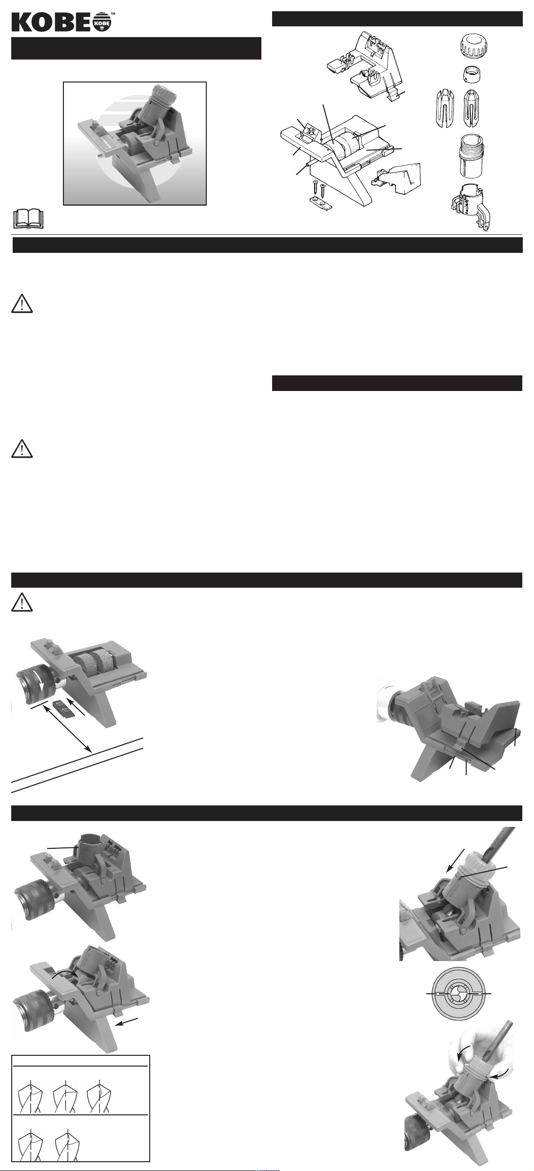
%&*!%&$'&"!%
" #"!!&%
42
Carriage
Nut
Collet
Ring
2 collets:
3-7mm dia.
8-13mm dia.
Turret
Turret
holder
Wood bit guide
Grinding bed
Silicon carbide
grinding wheel
(green)
Catch
Locating foot
Spindle
Chuck
guard
HSS drill setter
Aluminium oxide
grinding wheel (grey)
!&!!
;4666410
lDrill bits should be regularly sharpened and not allowed to become blunt especially
on masonry drill bits as the carbide tip wears much quicker when blunt.
;48/482@30066410
lThe grinding wheels should not be allowed to wear down to below 8mm from the grey
spacer (the plastic part between them) because the smaller diameter of the wheel
cannot produce the correct geometry and therefore it needs to be replaced before
continuing the sharpening of the drill bits.
!"& Always use the correct K BE replacement wheels to avoid possible injury.
These are available from your local K BE stockist.
;48/482@3006<>;1,.0
lIf the grinding wheel becomes unevenly worn, their surface can be restored by, for
example, an old masonry drill and simply running it from side to side across the wheel
while its rotating until the surface of the wheel is square again.
1=0;><0.,;0
lTo prevent the collet from developing a permanent ‘set’ unscrew the nut after use.
lRemove all abrasive dust.
%&'#
)$!! Do not leave the drill plugged in whilst tool is not in use or
whilst setting up. Do not use the hammer or reverse setting. Do not leave
the drill running for more than five minutes at any one time.
Approx. 125mm
(5inches) from edge
of bench
Slide
back
42
42
Turret Holder
42
Flip ‘Setter’ down
080;,6<0=>:
 To securely fix the sharpener to a
flat surface use the screws provided
fix the locating foot about 125mm
(5 inches) from the front edge of the
bench or suitable board <0042.
 Before securing the sharpener onto
the locating foot, fit the sharpener
spindle into the drill chuck ensuring
it is centered in the jaws and that
the chuck does not touch the chuck
guard. Tighten the chuck.
Now place the sharpener along with
the drill attached, over the locating
foot and slide it back to lock it into
position, placing the drill with the
handle forward so that there is no
strain on the foot.
#9@0;/;466
Ensure that the mains wall socket is
within easy reach. During use, lock the
drill ‘on’ using the trigger catch. Run
the drill at maximum speed but no more
than 3000rpm, maximim power 850 watt.
080;,6<3,;:08482
Use the grinding bed on it’s own. %00C080;,62;48/482,8/<3,;:08482D48=30
C":0;,=498D<0.=498
%%/;466<3,;:08482
Hook the carriage under the rear rail and place the other side of the carriage over the
front rail and lightly press down until you hear a click <0042
Slide the carriage to the right until it reaches the stop.
%00C%3,;:08482%%&@4<=;4664=<D48=30C":0;,=498D<0.=498
,<98;A/;466<3,;:08482
Starting with the carriage at the right-hand edge of the grinding bed <0042
repeat the procedure for the ‘HSS
drill sharpening’ above then
%00C%3,;:084827,<98;A/;466
-4=<D48=30C":0;,=498D<0.=498
)99/-4=<3,;:08482
See overleaf.
3,82482=30.9660=
Select the correct size collet for
your drill bit. The collet that comes already in
the turret is the tighter of the two and is for 3mm
to 7mm diameter drill bits. The other collet is for
the 8mm to 13mm drill bits. When changing
between the two collets unscrew the nut,
remove the collect ring and insert the correct
collet. Replace the collet ring with the lugs
downwards and replace the nut.
"#$&"!%$#!!%%&)%&$&%
 Set up the carriage for C%%/;466
<3,;:08482D see above.
 Place the turret holder into the
‘HSS’ slots on the carriage
pushing the support legs until they
click into position <0042
 Flip the drill setter down so it
touches the grinding wheel then
hold it lightly and slide the carriage
to the left until it clicks and locks
into position with the drill setter
<0042
 Select the correct size collet for
your drill bit then see C3,82482
=30.9660=Dsection above if a
change of collet is needed.
 Tilt the turret holder onto the right,
resting it on the upright part of the
carriage.
 Insert the drill bit into the turret
and turn the nut until the bit is a
loose fit and centred in the collet
(for 13mm drill bits insert by
disassembling the turret).
 Insert the turret (without the drill
bit in it) into the turret holder,
slotting either rib on the side of the
turret into the C%& %D on the
turret holder and push down fully
<0042
 Now insert the drill bit into the
turret <0042 and push down
firmly so it comes into contact with
the drill setter and the grinding
wheel. Then twist the drill bit
anti-clockwise until it lifts slightly
and then it will drop down into
position.
 Press the drill bit towards the
grinding wheel and then turn it
clockwise until you feel it stop.
Hold the drill bit in this position
with one hand and tighten the nut
with the other.
 Remove the turret from the holder
and check that the drill bit’s cutting
edges are parallel with the turret
nose index marks <0042
!"&If the drill bit position is not
correct, remove and repeat the
aligment procedure. 989=simply
turn it by hand.
 nce the alignment is correct slide
the cariage to the right and flip the
setter up.
 Replace the turret and drill bit in
the holder so either of the ribs
slots down into the wide slot
marked C%%D with the drill bit fully
over the left-hand grey grinding
wheel. Switch on the drill.
 Now press the red cam on the
turret up against the upright part of
the carriage and slowly and evenly
rotate the turret from one end of
the slot to the other about 10
times or until you hear that the
grinding has stopped
<0042
 Finally remove the drill bit from the
turret and compare it to the =,-60
on the left and if necessary make
the adjustments following the
table.
!"&Broken drill bits can be ground
to approximate shape <00=,-60 on
the silicon carbide (green) wheel, then
follow the instructions above. Whilst
sharpening to avoid uneven wear in
the grinding wheels slowly move the
carriage across the whole width of the
wheel with your left hand whilst
rotating the turret with your right.
If the grinding wheel is not flat it will
not grind the correct tip geometry,
see C;48/482@3006<>;1,.0Din the
C7,48=08,8.0D section above.
42
Stop
Front rail Catch
Rear
Rail
l!($ operate the tool when tired or under the influence of alcohol /prescription or
non-prescription drugs.
l!($ operate if any parts are missing or damaged.
l!($ leave the tool running whilst unattended.
l!($ modify the tool or accessories and only use it for the task for which it has
been designed.
l!($ force or apply excessive pressure on the tool.
l!($ touch moving or active parts of the tool or accessories.
l!($ work in a combustible atmosphere.
l!($ allow children to use or play with the tool.
42
42
42
Rib
Align cutting
edges of
tip with
index
marks
slowl &
evenl
rotate
&,-60HSS drill bit shape; 118° tip angle
&4:.60,;,8.0
Correct
;466:948=
Correct
Incorrect
insufficient
Incorrect
Unequal edges
Incorrect
excessive $070/A
Repeat
sharpening
operation,
ensuring
correct
alignment.
$070/A
Sharpen slightly more
on shorter side
"#$&"!%$#!! %"!$*$&%
The drill bit sharpener accurately sharpens
all 3 main types of masonry drill bits:
Conventional, Hammer and SDS-Plus.
Check the drill bit type first:
98?08=498,6 designed for use in standard
drills, has 2 edges on the angled tip.
,770; Tip relief angle is steeper and the
tip is ground back to give 4 edges for
improved performance.
%%#6><a combination of the 2 and 4 edged
types, and marked SDS-Plus on the shank.
 Set up the carriage for C ,<98;A/;466<3,;:08482D see C%0=':D overleaf.
Place the turret holder legs into the C %Dgroove on the carriage <0042
Press the lug on the right-hand side of the turret holder into one of the slots on
the upright part of the carriage until it clicks into place.
&@90/20-4=< use slot ‘2’
9>;0/20-4=< use slot ‘4’ which is the closest to ‘2’
%%#6><-4=< use slot ‘4’ furthest away from slot ‘2’
Select the correct size collet for your drill bit then see C3,82482=30.9660=D
section overleaf in C%0=':D if a change of collet is needed.
Insert the drill bit into the turret and turn the nut until the
bit is a ‘sliding fit’ (i.e held but still slides). Manoeuvre the
drill bit to ensure it is centred in the collet. For 13mm drill
bits disassemble the drill turret and insert the bit in from
the bottom.
Insert the turret into the turret holder, slotting either
rib on the side of the turret into the ‘SET/MAS’
on the turret holder and push down
fully <0042
9;,667,<98;A/;466-4=<
Push the drill bit down until it touches the right-hand (green) grinding
wheel. Rotate the bit until the side of the tip <0042 is aligned with
the line marked on the turret holder <0042. Tighten the nut but do
not over tighten.
Remove the turret from the holder and check that the drill bit’s cutting
edges are correctly aligned with the turret nose index marks
<00142. If not correct hold the turret assembly horizontal, slightly
loosen the nut and carefully turn the tip to the the correct position
without altering the amount the drill bit protrudes through the nose of the
turret.
 Replace the turret and drill bit in the holder so either of the ribs slots
down into the narrow slot marked C<0= %D with the drill bit fully over
the right-hand green grinding wheel. Switch on the drill.
 Slowly move the carriage forwards and backwards so the drill bit
makes contact with the whole width of the green wheel. repeat this 3
or 4 times keeping a light downward pressure on the turret
<0042
Remove the turret and turn it 180° and replace it in the holder with the
other rib in the narrow slot marked C<0= %DRepeat the sharpening
procedure. Check the 2 edges appear equally sharpened.
9>;0/20/3,770;-4=<%3,;:08:0;9::9<4=0
=308
To sharpen the other 2 edges, remove the turret holder
and refit it into the second slot marked ‘4’ (furthest away
from the ‘2’). Repeat the sharpening procedure, slowly
moving the carriage backwards and forwards but only
make 1 or 2 passes across the wheel since the edges to
be sharpened are narrower. Turn the turret through 180°
to sharpen the other edge.
%%#6><-4=<%3,;:08:0;9::9<4=0=308
Use slot ‘4’ closest to slot ‘2’ and sharpen as per
paragraphs 4 and 5 of this section.
!"&This step will only remove metal if there has been
excessive tip wear).
Finally, use slot ’2’ and sharpen as per paragraphs 4
and 5.
The drill bit sharpener can be used to sharpen centre point wood bits that have a 90° angle between the centre point and the cutting edges <0042
"#$&"!%$#!!!&$#"!&)""&%
Start by removing the turret holder and sliding carriage by lifting the catch on the carriage.
Place the wood bit guide on the grinding bed at an upward angle of 45° and slot the
narrow part of the wood bit guide around the flange between the 2 grinding wheels.
Press the guide down into the grinding bed so that it locks into position <0042
 Practice positioning the drill bit with the power to the drill off. Slowly feed the bit into the
channel on the guide <0042 with a downward pressure on the bit (to maintain
contact with the walls of the channel) and the outer tips positioned as shown
<0042
 As the the bit gets near to the grinding wheel turn the bit slowly clockwise until the
right-hand outer tip just touches the channel face at the front of the guide
It is important not to over-turn as this will cause the bit to lift. Feed the bit towards the
grinding wheel until edge CD makes contact with the wheel. Practice this a few times.
 Remove the bit and turn on the power to the drill. Feed the bit towards the wheel as
described in step 4 (above) until edge CD makes contact with the grinding wheel
maintaining a light pressure on the bit.
!"&To avoid over heating do not sharpen the bit for more than 30
seconds at a time.
Inspect the bit and repeat the procedure until the face is completely
ground. Rotate the drill bit and repeat for the other face.
 Finally check that the centre point of the bit is central. Regrind if
needed.
!"&The centre point of the bit might grind away to a ridge after
several sharpenings. This means that it will not centre itself correctly
whilst in use. To correct this, before sharpening the main faces
rotate the drill bit 90° from its usual position in the guide and sharpen
the 2 smaller faces of the centre point until a sharp point is obtained.
Take care not to grind the outer tips of the bit.
"#$&"!%$#!!&)""&%
!"&Practice the following before turning on the power to the drill.
 Hold the flat wood (spade) bit at the right-hand edge of the green wheel
<0042. Hold the bit above the grinding bed (usually, but not always
about 10mm) so that the angle of edge ‘A’ that is to be sharpened is parallel
with the wheel <0042
 Holding the bit firmly switch on the drill and sharpen edge CD.
Do not sharpen central spike.
 Turn the bit over and repeat on edge CD
"#$&"!!$$!!%$#!!
The drill bit sharpener also acts as a compact bench grinder for a range of grinding jobs: resharpening cold
chisels, glass drill bits, scribers, punches etc. Use only the silicon carbide grinding wheel (green).
Remove if assembled the sliding carriage and turret holder by lifting the catch on the carriage.
Start the drill and sharpen the tool using light, even pressure.
!"&If too much pressure is applied it will reduce the cutting rate.
Firmly hold the tool with part of it resting on the grinding bed <0042
#"$&!&
Smaller tools that cannot be supported in this way must be held in a clamp which itself must be adequately
supported. If this is not possible "!"&attempt to sharpen as they may slip down into the space around
the spinning wheels.
If the work has to be held radially to the wheel for example when edging a
screwdriver or square punch it is important that the part of the work nearest the
grinding wheel rests on the grinding bed <0042
When work has to be held in the shown position <0042 it must be
supported on the grinding bed pressing down to increase control.
!($grind/ sharpen pointed tools without handles unless you use a clamp to
hold the tool, otherwise you could injure yourself.
To prevent the uneven wear of the grinding wheels move the work across the
wheel whilst grinding.
"!"&allow the tools to overheat cool them with water.
"!"&grind close to a fine cutting edge.
"!"&grind soft materials such as brass, solder, lead, aluminium, plastic or
copper as these will clog the grinding wheels.
42
42
Green
Wheel
;008
)3006
;0A
)3006


Side view of
flat wood bit
10mm
Side view of grinding
bed (N.B. ‘central
spike of bit’ hidden
by wheel).
Top View of
grinding bed
42
Support the tool on the
grinding bed
42
42
42
/20

42
42
Right-hand tip just
contacts channel face
,<98;A/;466-4=<
&4:20970=;AB=4:,8260
98?08=498,6two-edge; 15° relief
angle
,770;four-edge; 15°/30° relief
angle
%%#6><two/four-edge; 15°/30°
relief angle
42
Lug
Clipped
into
position
42
42 Align cutting
edges of tip with
index marks
42
Side of tip
90°
;008
)3006
;0A
)3006

Other KOBE Power Tools manuals

KOBE HAG200-D User manual

KOBE

KOBE HAG200-D User manual

KOBE HP5040K User manual

KOBE

KOBE HP5040K User manual

KOBE R7722 User manual

KOBE

KOBE R7722 User manual

KOBE SR375 User manual

KOBE

KOBE SR375 User manual

KOBE FSR375 User manual

KOBE

KOBE FSR375 User manual

KOBE KBE-279-2300K User manual

KOBE

KOBE KBE-279-2300K User manual

Popular Power Tools manuals by other brands

Sherman + Reilly SRK15X Operation manual

Sherman + Reilly

Sherman + Reilly SRK15X Operation manual

Powerplus POWDP2530 manual

Powerplus

Powerplus POWDP2530 manual

BLACK DECKER RT18 manual

BLACK DECKER

BLACK DECKER RT18 manual

Thermaltronics TMT-HA200 user manual

Thermaltronics

Thermaltronics TMT-HA200 user manual

phase II+ 220-006 Operating instructions & parts manual

phase II+

phase II+ 220-006 Operating instructions & parts manual

FLORABEST FSG 85 B1 translation of original operation manual

FLORABEST

FLORABEST FSG 85 B1 translation of original operation manual

Toolshop 241-9834 Operator's manual

Toolshop

Toolshop 241-9834 Operator's manual

BLACK DECKER BDCINF18 Original instructions

BLACK DECKER

BLACK DECKER BDCINF18 Original instructions

OEM Tools 24491 Operating instructions and parts manual

OEM Tools

OEM Tools 24491 Operating instructions and parts manual

Pro's Kit SI-168U user manual

Pro's Kit

Pro's Kit SI-168U user manual

CO/Tech M1R-KZ3-8-UK Original instructions

CO/Tech

CO/Tech M1R-KZ3-8-UK Original instructions

Chef's Choice EdgeSelect Diamond Hone 120 instructions

Chef's Choice

Chef's Choice EdgeSelect Diamond Hone 120 instructions

Westfalia 80 84 65 instruction manual

Westfalia

Westfalia 80 84 65 instruction manual

Fayat Group BOMAG BPR 35/60 D Operating	 instruction

Fayat Group

Fayat Group BOMAG BPR 35/60 D Operating instruction

Flex GCE 6-EC manual

Flex

Flex GCE 6-EC manual

HammerSmith M32718 Instructions for use

HammerSmith

HammerSmith M32718 Instructions for use

Powerfix Profi PLPRS A1 operating instructions

Powerfix Profi

Powerfix Profi PLPRS A1 operating instructions

Milescraft Work Center 1098 owner's manual

Milescraft

Milescraft Work Center 1098 owner's manual

manuals.online logo
manuals.online logoBrands
  • About & Mission
  • Contact us
  • Privacy Policy
  • Terms and Conditions

Copyright 2025 Manuals.Online. All Rights Reserved.