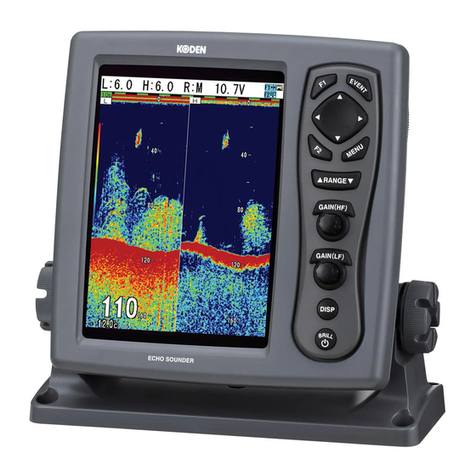
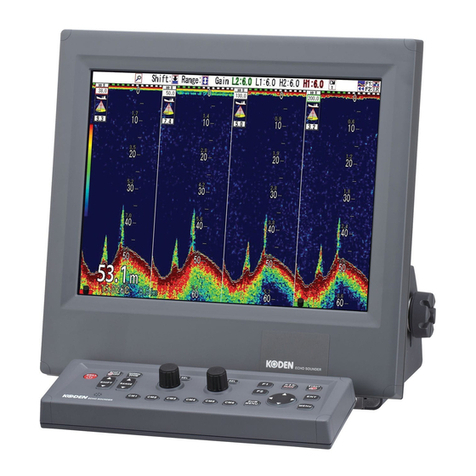
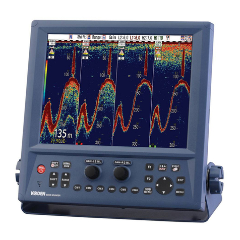
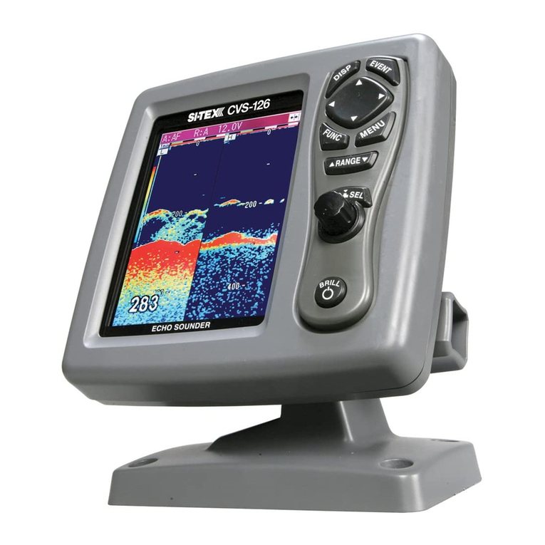
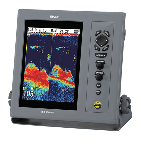
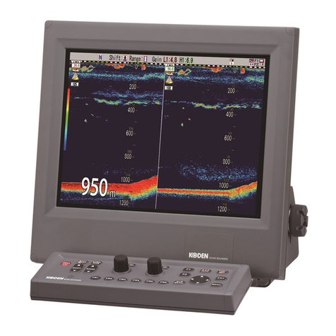
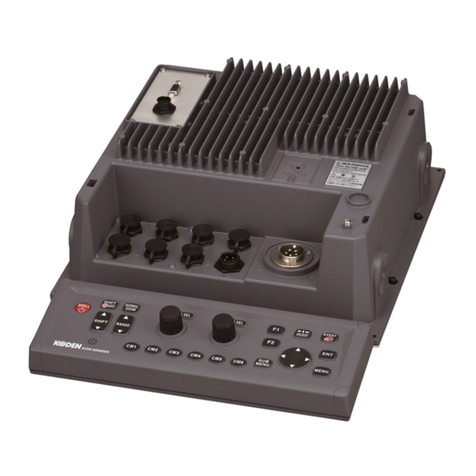
Koden CVS-841 User manual


AMENDMENT HISTORY
CVS-841/851 OPERATION MANUAL
Doc No: 0093132682
No. Document No & Rev No. Date
(D/M/Y)
Amendments
0 93132682-00 17/12/03
First issue
1 93132682-01 27/05/04
Cover Address
2 93132682-02 10/06/04
Chaper1,2,3,4,8,10 and Chaper5 Contents
3 93132682-03 10/10/04
Chaper4
4 0093132682-04 02/03/06
Cover
5 0093132682-05 29/05/06
Cover Chaper5
6 0093132682-06 16/08/06
Cover Chaper2
7
8
9
10
Amendment policy
When any change is applied in the document, only the document number of the relevant sheet(s) and
cover sheet are modified and the rest of the sheets are not changed. The document number is shown in
the footer area, right or left bottom of each sheet.
2003 2004 2005 2006 Koden Electronics Co.,Ltd. All rights reserved.
No part of this publication may be reproduced, transmitted, translated in any form by any means without
the written permission of Koden Electronics Co., Ltd. The technical descriptions contained in this
publication are subject to change without notice. Koden assumes no responsibility for any errors,
incidentals or consequential damages caused by misinterpretation of the descriptions contained in this
publication.

CVS-841/851 Preface
Safety Precautions
zHigh Voltage
High voltages are used in the transmitter section which could be life threatening. Aprotection cover with
the words Danger High Voltage is provided in this section but wait 10 minutes before inspecting inside.
Even if the power switch is turned off, residual voltages may remain in the capacitors inside the unit.
Before inspection or replacement of parts, discharge this residual voltage in a safe and correct manner.
zDisconnect Main Power
It is still possible to receive an electric shock caused by unintentionally switching on the power during
repair work. To prevent this from happening, make sure to completely disconnect the unit from the
ship’s main supply before attempting any inspection.
zDust
Dust can accumulate inside after long periods of use.Allergies can result from the inhalation of this dust,
therefore during inspection and cleaning it is advisable to use a mask.
zStatic Electricity
Static sensitive semiconductor devices are used in this unit. Before changing the printed boards be
careful not to damage any of these devices due to electrostatic build up from carpet, clothes, seats, etc
zDisplay Front Plate
A glass plate is used in front of the Liquid Crystal Display in the CVS-841 sounder unit. The glass is
vulnerable against mechanical impact. Use the utmost care when handling this unit, not to apply
mechanical shock to this part. In the CVS-851 sounder unit, a plastic plate is used for the same
purpose, which is stronger than the glass, however, the same caution should be taken.
zLiquid Crystal Display
A Liquid Crystal Display contains mercury, which is harmful to the human body when touched. When
you attempt to discard this device, follow the proper disposal procedures.
93132682-00 (1)

Preface CVS-841/851
Symbols used in this manual
The following symbols are used in this manual. You are requested to be fully aware of the meaning of
each symbol before carrying out inspection and maintenance of this equipment.
Alarm mark To handle the equipment ignoring this sign may lead to injury to the
human body or damage to the equipment.
Alarm
Caution mark
To handle the equipment ignoring this sign may lead to a
malfunction of the equipment.
Caution
Warning High Voltage mark
To handle the equipment ignoring this sign may lead to electrical
shock to the human body.
Prohibition mark
This sign indicates that a specified action is prohibited. The
prohibited action will be shown in the vicinity of the mark.
(2) 93132682-00

CVS-841/851 Preface
How to use this manual
Scope of this manual
This manual contains information about installation, operation and maintenance of the CVS-841/851
series of sounder.
Structure of this manual
This manual is divided into sections according to the contents as described below. This arrangement
will help you overview the whole of the contents as well as refer to detailed information for your specific
requirement.
Chapter 1: General Information
-General features of the equipment
-Applicable standard
-Equipment configuration
-Software type name
Chapter 2: Equipment Composition
-Standard equipment list
-Spare parts list
-Optional items list
-Available transducers list
Chapter 3: Specifications
-Functional specifications
-Power supply requirements
-Environmental conditions
-External dimensions and weight
Chapter 4: Installation
-Installation consideration
-Unpacking each component of the system
-Inspection of each component unit and accessories
-Siting the units
-Cable routing and connections
-Display installation
93132682-00 (3)

Preface CVS-841/851
-Internal connections of the system
-Check up after installation
-Connector’s pinouts
-Transducer installation
Chapter 5 : Basic Operation
-Operating controls and functions
-Getting started
-Displaying the dual images
-Operating the VRM
-Selecting the image speed
-Activating the IR function
-Operating the SHIFT key
-Using the Color Rejection function
-Setting the Alarm Function
-Operating the EVENT key
Chapter 6: Using Menu
-The key switches used
-Operating procedure of the menu driven functions
-Confirming the factory initial settings
-Menu list
-Descriptions of the menu functions
-Display
-Automatic (functions)
-System
-Customize
-Initialize
-Simulator
Chapter 7: Functional Registration
-Depth range registration
-Image mode registration
-Setting the Enhanced effect
(4) 93132682-00

CVS-841/851 Preface
93132682-00 (5)
Chapter 8: Trouble Shooting
-Information required for service
-Self check function
-Trouble shooting
-Setting the video threshold
Chapter 9: Maintenance
-Periodical inspection and cleaning
Chapter 10: Technical References
-Serial input data
-Details of input sentences
-Serial output data
-Data input/output serial line
-Data input serial line
Annex Sheets:
-User setting list
-Factory default list

CVS-841/851 Terminology
Operation Manual
Terminology
Alarming range
A user defined alarming range bar, which is displayed in the right side of the display. When a school of
fish or the seabed touches or enters this zone, an audio alarm will be activated.
A scope
Current echo signal is shown in a linear form at the right side of the screen, i.e. signal intensity in the
horizontal and depth in the vertical.
Bottom Alarm
The alarm that warns the existence of the sea bottom. The alarm is generated when the sounder has
detected the sea bottom within a preset depth.
Bottom Discrimination
Bottom image is zoomed with reference to the seabed. This feature allows an analysis of the sea
bottom, in addition to the type of fish school.
Bottom Lock
The sea bottom is always displayed flat with a normal display, which is shown on the upper half of the
screen. This allows easy finding of a fish school near the sea bottom and observing the entire sounder
image.
Bottom Zoom
The generic term of zoomed sea bottom presentations that includes the Bottom Lock, Bottom
Discrimination、and Bottom Zoom.
Color Alarm
An audible alarm function that is triggered when the sounder detects a school of fish in a specific color.
The color can be specified by the operator via the menu.
Comparison Mode
A video processing method to discern a weak fish school out of a large mass of fish schools. This
mode displays the result of the comparison between HIGH and LOW frequency echoes. If those
echoes are overlapped at the same depth, the resultant colors are displayed in mixed colors. However,
if the HIGH frequency echo is displayed in red (strongest color), the mixed color will also be red to
show the echoes are from small fish. If the mixed fish school is partly displayed with mixed colors
among red color, it suggests the possibility of a larger fish school among the small fish school.
93132682-00 (1)

Terminology CVS-841/851
Operation Manual
Distance Traveled
A logged distance the ship has made. This feature is available only when the speed sensor device is
installed.
Draft Line
A sub menu function that adjusts the transducer depth in order to obtain the correct sounding depth in
shallow waters.
Dual frequency Mix
A sonar video processing method to detect weak schools of small fish like anchovy, utilizing the
sounder’s inherent characteristic that small fish are sensitive to high frequency sonar pulses but
insensitive to low frequency.
Dual Frequency Normal
A mode of screen presentation in that both high and low frequency images are shown on the screen.
Echo Length Alarm
An audible alarm function that is triggered when the sounder detects a school of fish of a certain length.
The length can be specified by the operator via the menu.
Fish Alarm
An audible alarm function that is triggered when a school of fish, which size and color are specified,
exists within a predetermined alarming depth range.
Fix Shift
Using this mode, the image starts from a preset depth within a selected range.
Format
The arrangement of the navigational data sentence supplied from an external navigator device.
Gain
The degree of the receiver sensitivity, which can be controlled by the operator’s GAIN control (HIGH or
LOW).
Gain Control Law
A sub menu function that selects the receiver gain control law. The selectable law is Linear and Log.
(2) 93132682-00

CVS-841/851 Terminology
Operation Manual
Image Speed
The rate of the image feed, which is related to the frequency of the transmission, for instance, 2/1
means the image shifts twice every transmission.
Inner Hull Installation
A method of transducer installation; transducer is installed inside the bottom of the hull using the
optional inner hull kit MFB-04.
IR (Interference Rejection)
The name of the operating key switch that allows, when switched in, reducing interference caused by
other ship’s sounders.
Linear
A gain control characteristic in which receiver gain changes in a linear law (proportional to gain control),
which is best suited for shallow water fishing and detection of weak schools of fish.
Log
A gain control law in which receiver gain changes in a log law (steep rise at first then gentle rise), best
suited for deep sea fishing.
Navigation Data (B.N)
Navigational data supplied from a navigator unit is shown such as, ship’s own position, speed, bearing,
waypoints, etc.
Peak Hold
A video processing method, comparing two consecutive sonar video signal in order to output the
largest one as the real sonar video.
Pulse Width
The width of the sonar pulse; wider pulse allows better detection of fish school but lack of definition
and vice versa.
STC (Sensitivity Time Control)
As the name indicates, the receiver sensitivity is controlled according to the time (depth), to help
detection of a school of fish in shallow murky water caused by the existence of plankton or some other
forms of marine life.
93132682-00 (3)

Terminology CVS-841/851
Operation Manual
Simulator
A simulated sonar video image shown on the screen, which is useful to get the hang of the sounder
operation before using it in the field.
Sonic Correction
The correction method of a deviated depth display caused by the change of water temperature or
salinity.
Subtraction Mode
A video processing method to discern a weak fish school in a mixed image containing a large mass of
a fish school. This is done by subtracting LOW frequency video from HIGH frequency video. If the
resultant echoes are displayed in similar colors as the HIGH frequency echoes, this result suggests
the majority of the fish species is sensitive to HIGH frequency transmission, i.e. the detected fish
school could be small fish like young sardine. If the resultant colors are shown in different colors from
HIGH frequency transmission, it indicates the fish school is sensitive to LOW frequency, therefore, a
larger size of fish species.
Synchronization with External Sounder
This function is used to reduce interference from other sounders operated on the same ship by
synchronizing the transmission timing.
Through-hull Installation
A method of transducer installation; transducer is installed on the bottom of the hull.
Upper Depth
The upper limit depth defined in a specific partial zoom mode. If any fish school or the seabed lies in a
shallower depth than this depth, it is not detected as a seabed.
VRM (Variable Range Marker)
A movable depth marker shown in a green line, used to measure the depth in higher accuracy.
White Line
The bottom surface is shown in a white band shape. This feature is useful in discerning a school of
fish near the seabed.
Zoom Start Depth (Upper depth limit)
The upper depth limit from which partial zooming starts.
(4) 93132682-00

CVS-841/851 Terminology
Operation Manual
93132682-00 (5)
Zoom Range
The name of a sub menu, which allows selecting the zooming range of the following image modes;
Bottom Lock, Bottom Discrimination and Bottom Zoom.

CVS-841/851 Main Contents
Operation Manual
Main Contents
Chapter 1 General Information
Chapter 2 Equipment Composition
Chapter 3 Specifications
Chapter 4 Installation
Chapter 5 Basic Operation
Chapter 6 Using the Menu
Chapter 7 Functional Registration
Chapter 8 Trouble Shooting
Chapter 9 Maintenance
Chapter 10 Technical Reference
Annex Sheets
93132682-00 Main Contents

CVS-841/851 Chapter 1
Operation Manual General Information
Chapter 1 General Information
Contents
Page No.
1.1 General features of the equipment.........................1-1
1.2 Applicable standard.................................................1-1
1.3 Equipment configuration.........................................1-1
1.4 Software type name .................................................1-2
93132682-00 Contents

CVS-841/851 Chapter 1
Operation Manual General Information
Chapter 1 General Information
1.1 General features of the equipment
The CVS-841/851 series sounder is designed to meet stringent demands of the professional
fishermen, featuring a 10.4 inch or 15 inch color LCD display, a dual frequency, 1 kW or 3 kW power
output. According to the display size and power level the model name is designated as follows:
CVS-841C: The screen size is 10.4 inch (Diagonal) arranged in portrait mode with the 1 kW output.
CVS-851C: The screen size is 15 inch (Diagonal) arranged in landscape mode with the 1 kW output.
CVS-841P: The screen size is 10.4 inch (Diagonal) arranged in portrait mode with the 3 kW output.
CVS-851P: The screen size is 15 inch (Diagonal) arranged in landscape mode with the 3 kW output.
The CVS-841/851 series is composed of a display unit with a built-in TX/RX (Transmitter/Receiver)
module and a transducer device. General features of each model are as follows:
Display unit: This unit uses a high brightness, TFT (Thin Film Transistor) Liquid Crystal Display (LCD)
to allow easy viewing in daytime and nighttime operations. The screen size and its arrangement of the
display unit vary according to the type.
TX/RX module: This module is composed of the transmitter and receiver sections, contained in the
display unit. Changing the settings on the printed board of this module can change the transmitting
power level and frequency. The output power can be selected from 1 kW (CVS-841C/851C) or 3 KW
(CVS-841P/851P) and the frequency from 28 kHz, 38 kHz(or 40 kHz), 50 kHz, 75 kHz or 200 kHz.
All controls of the sounder unit can be performed from the display unit. The operation is simple and
straightforward; using dedicated rotary controls and tactile keypads with user-friendly menus. The unit
can be set to hands-free operation, where the gain and depth range are automatically selected to an
optimized level by a micro-controller chip. The display unit is a splash proof design, meeting IPX5
technical standard.
1.2 Applicable standard
The CVS-841/851 series of sounder is designed and tested to comply with the international standard
of IEC-60945 3rd edition that defines general requirements of electronic maritime equipment.
1.3 Equipment configuration
The CVS-841/851 system composition is shown in Table 1.1 (Refer to Figure 1.1 for the system
configuration diagram)
93132682-01 1-1

Chapter 1 CVS-841/851
General Information Operation Manual
Table 1.1 Type names of component units
Model name Output Transducer
TD-282 28kHz
TD-401D 38kHz(or 40 kHz)
TD-501B 50kHz
TD-751 75kHz
CVS-841C
CVS-851C
1kW
TD-2001D 200kHz
TD-284 28kHz
TD-404T 38kHz(or 40 kHz)
TD-504T 50kHz
TD-504F 50kHz
TD-754 75kHz
CVS-841P
CVS-851P
3kW
TD-66 200kHz
NOTE: The output available from 200 KHz transducer type TD-66 used for CVS-841P/851P is 1 kW.
Dual Frequency TD
Output Output Transducer
TD-501C 50/200 kHzCVS-841C
CVS-851C 1 kW TD-501T-3 50/200 kHz
1.4 Software type name
CVS-841:
Software type name Application
KMC-82 System control
CVS-851:
Software type name Application
KMC-83 System control
1-2 93132682-01

CVS-841/851 Chapter 1
Operation Manual General Information
93132682-01 1-3
Display
CVS-841/851
DC Power Cable
CW-253-2M (2m)
100/110/115 VAC
200/220/230 VAC
Transducers
NMEA In/Out
To other sounder
AC Power Cable
VV-2D8-3M (3m)
CW-371-5M (5m)
CW-372-5M (5m)
CW-373-5M (5m)
CW-374-5M (5m)
CW-375-5M (5m)
CW-376-5M (5m)
CW-373-5M (5m)
CW-374-5M (5m)
CW-375-5M (5m)
CW-376-5M (5m)
CW-376-5M (5m)
GPS
(KGP)
Decca
(DR)
CW-60-10M (10m)
CW-154A-5M (5m)
CW-352-5M (5m)
CW-328-5M (5m)
CW-60-10M (10m)
CW-60-10M (10m)
CW-154A-5M (5m)
TD Cable
CW-836-3M
J5(6 pin)
J2(6 pin)
J4
(
7
p
in
)
POWER
J3(8 pin)
J6(5 pin)
A
ttached cable (10m)
GPS Sensor
(GPS-10A B Type)
(KBG-1/2 B Type )
Navigator
Unit
Loran
(LR)
Junction Box
JB-10/JB-12
AC/DC
Rectifier
PS-006
10.8 - 31.2 VDC
(NOTE 2)
Junction Box
JB-32
Transducer
Extension Cable
VSV-2T11-3M
Cable
gland
Speed/Temperature
sensor with cable and
connector
ST-80-1
ST-90-1
ST-100-1
NOTE 1: A section in a dotted block is an optional item.
NOTE 2: The Junction Box JB-32 is available for long cable connections.
Figure 1.1 System configuration of CVS-841/851 series sounder

CVS-841/851 Chapter2
Equipment Composition
Chapter 2 Equipment Composition
Contents
Page No.
2.1 Standard equipment list.........................................................2-1
2.2 Spare parts list........................................................................2-1
2.3 Optional items list ..................................................................2-1
2.4 Available transducers list ......................................................2-2
93132682-00 Contents

CVS-841/851 Chapter 2
Equipment Composition
Chapter 2 Equipment Composition
2.1 Standard equipment list
No Item name Type name Remarks Weight/Length Q’ty
CVS-841C/P With base mount 6.8 kg1 Display CVS-851C/P With base mount 10.5 kg 1
2 DC cable CW-253-2M For Display Unit 2m 1
3 TD cable CW-836-3M For Transducer 3m 1
4 Spare parts Detail in Spare Parts List 1 set
5 Operation
manual English
1 set
2.2 Spare parts list
No. Item name Type name Remarks Weight/Length Q’ty
1 Fuse F-7161-10A
/N30C-125V For Display Unit 1
2.3 Optional items list
No. Item name Type name Remarks Weight/Length
ST-80-1 Transom
(Plastic, with cable fitted) 0.3Kg
ST-90-1 Inner hull
(Plastic, with cable fitted) 0.6Kg
1 Temperature/
speed sensor
ST-100-1 Through hull
(Bronze, with cable fitted) 1.2Kg
J7-101 Single frequency 1.6kg
2 TD Switch J8-201 Dual frequency 2.2kg
3 Inner hull kit MFB-04W Plastic, applicable for 1KW only 1.5kg
4 Kingston kit MFB-05W Applicable for 1KW only 0.83kg
5
Junction Box for
TD connections
JB-32 For dual frequency 2.0kg
JB-10 1 input, 3 outputs × 2 circuits 0.4kg6 Junction Box
for Navigator
unit connection
JB-12 1 input, 3 outputs, 3 inputs,
1 output 0.42kg
7 AC/DC
Rectifier PS-006 With 2 pcs of 10A fuse attached 8.0kg
VV-2D8-3M Both ends fly leads (For power
supply) 3m
8 Extension
cable
VSV-2T11-3M Both ends fly leads (For TD)
9 Earthing lead OW7/1.6S-3M 3m
Connecting
cable CW-371-5M 5P connector
/5P waterproof connector (LTW) 5m
10
(For external
sounder) CW-372-5M
Fly leads/5P waterproof connector
(LTW)
5m
CW-373-5M 6P waterproof connector both
ends (LTW) 5m
11 Connecting
cable
(Fornavigatorunit) CW-374-5M
6P connector/6P waterproof
connector (LTW) 5m
0093132682-06 2-1

Chapter 2 CVS-841/851
Equipment Composition
2-2 0093132682-06
No. Item name Type name Remarks Weight/Length
CW-375-5M
6P waterproof connector (Conxall)
/6P waterproof connector (LTW) 5m
(11) Connecting
cable (For
navigator unit) CW-376-5M Fly leads
/6P waterproof connector (LTW) 5m
CW-60-10M BNC/Crimp terminal 10m
CW-154A-5M 6P Connector/Fly leads 5m
CW-352-5M 6P waterproof connector
(Conxall)/Crimp terminals 5m
12 Connecting
cable (For
Navigator Unit
and Junction
Box) CW-328-5M
6P waterproof connector (Conxall)
/
Crimping terminals 5m
LTWBD-05BFFA
-L180 5P waterproof connector (LTW)
for external sounder
LTWBD-06BFFA
-L180
6P waterproof connector (Conxall)
for NMEA0183
13 Connector
female
LTWBD-08BFFA
-L180 8P waterproof connector (LTW)
for 8water/temperature sensor
CG-1 For steel hull, single frequency 1.5Kg
CG-2 For steel hull, dual frequency 1.5Kg
CG-3 For wooden hull,
single frequency 2.5Kg
CG-4 For wooden hull, dual frequency 3.5Kg
CG-16 For FRP hull, single frequency 0.9Kg
CG-18 For FRP hull, dual frequency 1.8Kg
14 Cable gland
CG-19 For wooden/FRP hull,
single frequency 1.0Kg
CVS-841/851.OM.J Japanese15 Operation
manual CVS-841/851.OM.E English
CVS-841/851.SM.J Japanese16 Service manual
CVS-841/851.SM.E English
17 transducer See 2.4 Available transducer list.
2.4 Available transducers list
Single Frequency TD
Output Type name Frequency Weight
TD-282 28 kHz 7.0 kg
TD-401D 38 kHz(or 40 kHz) 5.0 kg
TD-501B 50 kHz 4.2 kg
TD-751 75 kHz 4.2 kg
1 kW
TD-2001D 200 kHz 4.2 kg
TD-284 28 kHz 11.0 kg
TD-404T 38 kHz(or 40 kHz) 11.0 kg
TD-504T 50 kHz 11.0 kg
TD-504F 50kHz 10.0kg
TD-754 75 kHz 6.5 kg
3 kW
TD-66 (See NOTE) 200 kHz 4.2 kg
NOTE: The effective power output available from the 3 kW/200 KHz transducers is 1 kW.
Dual Frequency TD
Output Type name Frequency Weight
TD-501C 50/200 kHz 4.2 kg1 kW TD-501T-3 50/200 kHz 3.4 kg
This manual suits for next models
4
Table of contents
Other Koden Marine Equipment manuals

Koden
Koden CVR-010 User manual

Koden
Koden CVS-702D Assembly instructions

Koden
Koden CVS-875D User manual

Koden
Koden CVS-FX1 Assembly instructions

Koden
Koden CVS-128 User manual

Koden
Koden CVS-126 User manual

Koden
Koden CVS-833 User manual

Koden
Koden CVS-128 User manual

Koden
Koden CVS-126 User manual

Koden
Koden CVS-FX1 Assembly instructions

Koden
Koden CVS-126 User manual

Koden
Koden CVS-705D User manual

Koden
Koden CVG-200 User manual

Koden
Koden CVS-1410B User manual

Koden
Koden CVS-FX2 User manual

Koden
Koden CVS-128 User manual

Koden
Koden CVS-FX1 User manual

Koden
Koden CVS-FX2BB Assembly instructions
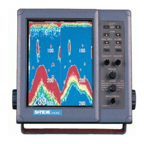
Koden
Koden CVS-872D User manual

Koden
Koden CVS-FX2 User manual