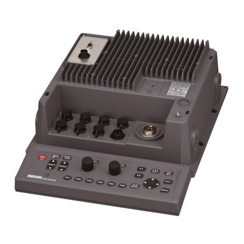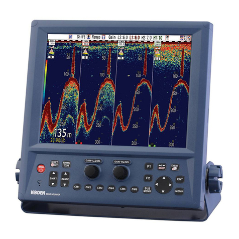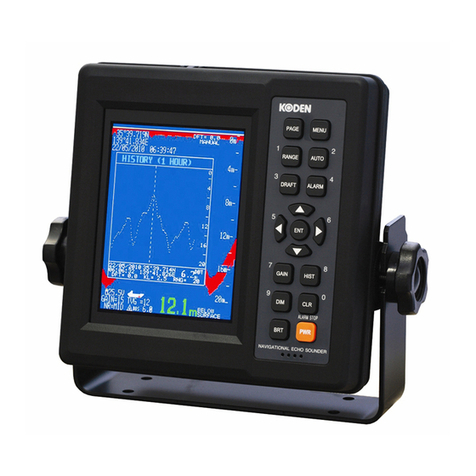
CVR–010
List of Contents
v
List of Contents (3/3)
11. User–Level Trouble Shooting .............................................................................................................71
11.1. Introduction ..................................................................................................................................71
11.2. Depth Readout.............................................................................................................................71
11.3. Automatic Range Selection..........................................................................................................72
11.4. Bottom Echo Appearance.............................................................................................................72
11.5. Alarms..........................................................................................................................................73
11.6. Soundings Data History Window..................................................................................................73
11.7. Settings through Menu System ....................................................................................................74
11.8. Date/Time Indication.....................................................................................................................74
11.9. GPS–Derived Data Outputs .........................................................................................................74
12. User–Level Maintenance Instructions.................................................................................................75
12.1. Maintenance on the Equipment Cabinet ......................................................................................75
12.2. Maintenance on Electrical Connections .......................................................................................75
12.3. Maintenance on The Transducer..................................................................................................75
12.4. Servicing the Equipment ..............................................................................................................76
12.5. Resetting the System...................................................................................................................76
12.6. Temporary Display of A–Scope ....................................................................................................77
13. Installation Instructions.......................................................................................................................78
13.1. Display Cabinet Installation..........................................................................................................78
13.1.1. General Precautions 78
13.1.2. Mounting 78
13.1.2.1. Mounting the Cabinet.....................................................................................................78
13.2. Transducer Installation.................................................................................................................80
13.2.1. General Precautions 80
13.2.2. Choosing Installation Location 80
13.2.3. Matched Transducers 81
13.2.4. Selection of AUTO TVG Response Characteristics for Transducers 81
13.2.5. Transducer Dimensions 82
13.3. Electrical Connections..................................................................................................................84
13.3.1. Introduction 84
13.3.2. Power Supply Connections 85
13.3.2.1. Power Supply Requirements and Power Cord Routing .................................................85
13.3.2.2. Connections...................................................................................................................85
13.3.2.3. Installing the Fuse..........................................................................................................85
13.3.2.4. Grounding the Display Cabinet......................................................................................86
13.3.3. Connections to Transducer 86
13.3.4. Connections through Digital I/O Interface Connectors 88
13.3.4.1. Introduction....................................................................................................................88
13.3.4.2. Approved Digital Displays..............................................................................................88
13.3.4.3. Input Data and Command Sentences............................................................................88
13.3.4.4. Navigational Output Data Sentences.............................................................................89
13.3.4.5. Alarm–Related Output Data Sentences.........................................................................92
13.3.4.5.1. Introduction..............................................................................................................92
13.3.4.5.2. Output Sentences for IEC 61162–1 Ed. 4 Alarm Handling Protocol ........................92
13.3.4.5.3. Alarm Output Intervals for IEC 61162–1 Ed. 4 Alarm Handling Protocol..................93
13.3.4.5.4. Output Sentences for IEC 61162–1 Ed. 5 Alert Handling Protocol .........................95
13.3.4.6. Connector Pin Assignments...........................................................................................98
13.3.5. Connections to ALARM ACK Connector 100
13.3.6. Connections to ALARM OUT Connector 101
14. Recommended Spare Parts..............................................................................................................102
