Français
Notice de montage KomLoc® Système de serrage HSK „K“
Aucun outil spécial n’est nécessaire au montage et démontage !
• Insérer l’élément de serrage KomLoc® dans l’emplacement baïonnette de la
broche filetée.
• Faire tourner l’élément de serrage KomLoc® de 90°
• Positionner le côté d‘utilisation suivant votre choix. La marque rouge sur la
broche filetée indique le filetage à gauche ! Attention, ne pas utiliser ce côté
d‘actionnement comme actionnement régulier. En cas d‘utilisation régulière
de ce côté, établir une documentation et un marquage.
• Visser la goupille filetée en butée puis desserrer d’un tour. Cette goupille
est mise en sécurité contre le desserage.
Démontage
• Dévisser la goupille filetée
• Tourner l’élément de serrage KomLoc® de 90° et le retirer du corps.
Entretien
• La broche filetée ne doit jamais fonctionner à sec, utiliser la pâte Molykote
G-n plus ou un lubrifiant ayant les mêmes propriétés.
Note: Les données d’utilisation indiquées sont fonction des conditions d’environnement et d’utilisation (telles
que machine, température ambiante, lubrifiant/produit de refroidissement et résultat d’usinage recherché): elles
supposent des conditions et une utilisation correcte ainsi que le respect des vitesses limites indiquées des outils.
Couple de serrage · Coppie di serraggio · 起始扭矩
Taille HSK · Grandezza HSK · HSK尺寸 25 32 40 50 63 80 100
Taille clé · Chiave di servizio · 操作扳手尺寸 2 2,5 3 4 5 6 8
Couple de serrage* · Coppia di serragio*
· 起始扭矩* Nm 1,5 2,5 6 10 15 25 60
Force de serrage · Forza di bloccaggio · 夹紧力度 kN 5,5 9 20 31 40 50 70
xD1
L2
L1
xD2
5
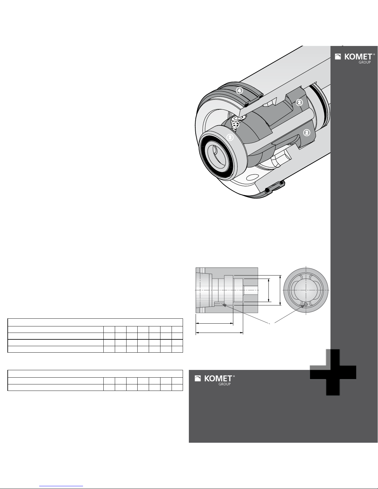
1 Broche filetée
Vite di bloccaggio
双头螺栓
2 Patte de serrage
Prinze di serraggio
夹紧装置
3 Cage
Espulsore
笼头
4 Bague de fermeture
Anello di protezione
卡簧
5 Goupille filetée
Vite di posizionamento
紧固螺钉
Non sono necessari estrattori o utensili speciali.
• Inserire il meccanismo KomLoc® nella sede del mandrino.
• Ruotare il meccanismo KomLoc® di 90° nella sede con innesto a baionetta.
• Il lato operazionale può essere posizionato facilmente come segue: Il lato
contrassegnato con un punto rosso è quello da non usare perchè ha filetta-
tura sinistra! Non attivare il meccanismo dal lato marcato di rosso. In caso di
necessità marcare il lato corretto per la attivazione e dare istruzioni operative
e documentazione appropriate.
• Avvitatre la vite di posizionamento a fine corsa quindi allentarla di un giro
completo. La vite è protetta contro lo svitamento accidentale.
Istruzioni per lo smontaggio
• Svitare la vite di posizionamento
• Ruotare il meccanismo KomLoc® di 90° ed estrarlo dalla sede mandrino.
Manutenzione
• Assicurarsi che la vite di bloccaggio sia sempre lubrificata con pasta Mo-
lykote G-n plus o equivalente o lubrificante con identiche proprietà.
Nota: I dettagli applicativi riportati nel presente catalogo dipendono dalle condizioni ambientali ed
applicative (Ad esempio: stato della macchina, temperatura dell’ambiente, tipo di refrigerazione usato,
risultati richiesti ecc.). Queste ultime sono soggette alla corretta applicazione degli utensili e alla osserv-
anza dei limiti di rotazione massima ammessi per ciascun specifico utensile.
* Suivant l’utilisation le couple de serrage peut varier de ±15%.
* In relazione all`utilizzo, la cppia di serragio può essere variata entro ±15%.
* 根据操作方式扭矩调节范围为±15%之内。
3
2
2
4
1
注意: 应用细节根据环境和应用条件(比如机床,环境温度,使用的润滑剂/冷却液,机床
所需的结果)来决定,这些都受限于适当的使用环境,刀具主轴限制转速的适当使用。
Filetage
Vite
螺钉螺纹
Taille de clé
Chiave mm
扳手尺寸
M2 0,9
M2,5 1,3
M3 1,5
M4 2
M5 2,5
M6 3
M8 4
Sécurité avec goupille filetée
Vite di posizionamente · 固定紧固螺钉
Sous réserve de changements techniques dus au développement. · Con riserva di modifiche tecniche
senza preaviso. · 我们保留修改权。
Italiano
Istruzioni per il montaggio KomLoc® sistema di bloccaggio HSK „K“
中文
安装说明 KomLoc® HSK夹紧装置系统 „K“
不需要特殊的工具!
• 将KomLoc®夹紧装置放入主轴上的卡口凹槽内
• 旋转KomLoc®夹紧装置90°
• 此时活动块到所需位置。侧面双头螺栓的红色标记表示反螺纹, 使用时
注意反螺纹的正确操作方法。.
• 尽可能的转动紧固螺钉到底再回转一圈。这样紧固螺钉就被卡簧固定防止松动。
卸载
• 松开紧固螺钉
• 旋转KomLoc®90°然后从刀体上移出
维护
• 保持螺纹销有充分润滑,如有需要,可是加点Molykote G-n或者具有相同
润滑属性的润滑剂。