RIDGID 915 User manual

In Place
Roll Groover
OPERATOR’S
MANUAL
915
WARNING!
Read this Operator’s Manual
carefully before using this
tool. Failure to understand
and follow the contents of this
manual may result in serious
personal injury.
99 Washington Street
Melrose, MA 02176
Phone 781-665-1400
Toll Free 1-800-517-8431
Visit us at www.TestEquipmentDepot.com

915 In Place Roll Groover
manufacturer for your model. Accessories that may
be suitable for one tool may become hazardous when
used on another tool.
•Keep handles dry and clean; free from oil and
grease. Allows for better control of the tool.
Service
•Tool service must be performed only by qualified
repair personnel. Service or maintenance performed
by unqualified repair personnel could result in injury.
•When servicing a tool, use only identical replace-
ment parts. Follow instructions in the Maintenance
Section of this manual. Use of unauthorized parts or
failure to follow maintenance instructions may create a
risk of injury.
Specific Safety Information
WARNING
Read this operator’s manual carefully before using
the 915 Roll Groover. Failure to understand and
follow the contents of this manual may result in
serious personal injury.
Roll Groover Safety
•Keep fingers away from rolls when grooving
pipe. Keep Sleeves and jackets buttoned. They
can become pinched resulting in serious injury.
•Do not wear loose fitting gloves. Can become
caught in rolls resulting in serious injury.
•Handle pipe carefully and have all burrs removed
from ends. Eliminates the risk of cuts to fingers and
hands.
•When working overhead, all personnel should
wear hard hats and be clear of the area below.
Prevents serious injuries if roll groover or workpiece
falls.
•Groover is designed to manually roll groove pipe
and tubing. Other uses may result in injury.
•Do not use power activated devices to aid in rotat-
ing the groover. Using a tool in a manner not intend-
ed can result in injury.
SAVE THESE INSTRUCTIONS!
Ridge Tool Company
2
General Safety Information
WARNING! Read and understand all instructions. Failure
to follow all instructions listed below may
result in serious personal injury.
SAVE THESE INSTRUCTIONS!
Work Area Safety
•Keep your work area clean and well lit. Cluttered
benches and dark areas invite accidents.
•Keep bystanders, children, and visitors away while
operating a tool. Distractions can cause you to lose
control.
•Keep floors dry and free of slippery materials
such as oil. Slippery floors invite accidents.
Personal Safety
•Stay alert, watch what you are doing and use com-
mon sense when operating a tool. Do not use tool
while tired or under the influence of drugs, alcohol,
or medications. A moment of inattention while oper-
ating tools may result in serious personal injury.
•Dress properly. Do not wear loose clothing or
jewelry. Contain long hair. Keep your hair, clothing,
and gloves away from moving parts. Loose clothes,
jewelry, or long hair can be caught in moving parts.
•Do not overreach. Keep proper footing and bal-
ance at all times. Proper footing and balance enables
better control of the tool in unexpected situations.
•Use safety equipment. Always wear eye protection.
Dust mask, non-skid safety shoes, hard hat, or hearing
protection must be used for appropriate conditions.
Tool Use and Care
•Do not force tool. Use the correct tool for your
application. The correct tool will do the job better
and safer at the rate for which it is designed.
•Store idle tools out of the reach of children and
other untrained persons. Tools are dangerous in
the hands of untrained users.
•Check for misalignment or binding of moving
parts, breakage of parts, and any other condition
that may affect the tool's operation. If damaged,
have the tool serviced before using. Many acci-
dents are caused by poorly maintained tools.
•Use only accessories that are recommended by the

Ridge Tool Company 3
Description, Specifications
and Equipment
Description
The RIDGID No. 915 Roll Groover is designed to man-
ually form standard roll grooves on pipe or copper tube
that is installed. The 915 is lightweight, only 23 lbs., and
capable of grooving steel, stainless steel, PVC and alu-
minum pipe from 11/4″to 12″and 2″to 8″copper tube
(Type K, L, M, and DWV). The 1/2″hand ratchet rotates
a feed screw that advances a groove roll into the
pipe/tube to form a groove that meets specifications
required for mechanical coupling systems, and also
drives the 915 around the pipe.
When properly used, the Model 915 Roll
Groover makes grooves that are dimensionally within the
specifications of AWWA C606-87. Selection of appro-
priate materials and joining methods is the responsibil-
ity of the system designer and/or installer. Before any
installation is attempted, careful evaluation of the specific
service environment, including chemical environment
and service temperature, should be completed.
Specifications
Capacity ........................Standard 2″– 6″Schedule 10
and 2″– 31/2″ Schedule 40
Steel Pipe
Depth Adjustment..........Feed Screw with 1/2″Female
Drive
Actuation........................Feed Screw with 1/2″Ratchet
Wrench
Weight............................23 lbs.
With Roll Changes:
• 2″– 8″ Copper Tube,
Type K, L, M, DWV
• 11/4″and 11/2Schedule 10 and 40 Steel/Stainless
Steel Pipe
• 4″– 6″Schedule 40
Steel/Stainless Steel Pipe
• 8″– 12″Schedule 10
Steel/Stainless Steel Pipe
(See Table II for Wall Thickness.)
Standard Equipment
Model 915......................Groove set for
2″– 6″Schedule 10 and
2″– 31/2″Schedule 40
1/2″Drive Ratchet w/button
release
Figure 1 – 915 Roll Groover
Accessories
• Groove set for 11/4″to 11/2″ Schedule 10 & 40 pipe.
• Groove set for 4″to 6″Schedule 40 pipe.
• Groove set for 8″– 12″Schedule 10.
• Copper groove set for 2″to 8″Copper Tube
Type K, L, M, DWV.
• Carrying case for 915 and roll sets.
The 915 Roll Groover is a portable unit designed for occa-
sional use on the jobsite and should not be used for high
volume work.
Roll Groover Inspection
WARNING
To prevent serious injury, inspect your Roll
Groover. The following inspection procedures
should be performed on a daily basis:
1. Inspect the Roll Groover for any broken, missing,
misarranged or binding parts as well as any other
conditions which may affect the safe and normal
operation of this equipment. If any of these conditions
are present, do not use the Roll Groover until any
problem has been repaired.
2. Lubricate the Roll Groover if necessary according
to the Maintenance Instructions.
915 In Place Roll Groover
CAUTION

Ridge Tool Company
4
3. Use groover rolls and accessories that are designed for
your Roll Groover and meet the needs of your appli-
cation. The correct groover tools and accessories
allow you to do the job successfully and safely.
Accessories designed for use with other equipment
may be hazardous when used with this Roll Groover.
4. Clean any oil, grease or dirt from all handles and
controls. This reduces the risk of injury due to a tool or
control slipping from your grip.
5. Inspect the groove rolls to insure they are not dam-
aged or worn. Worn groover rolls can lead to slippage
and poor quality grooves.
Roll Groover and
Work Area Set-Up
WARNING
To prevent serious injury,
proper set-up of the Groover and work area is
required. The following procedures should be fol-
lowed to set-up the machine:
1. Insure work area has adequate lighting.
2. Clean up the work area prior to setting up any equip-
ment. Always wipe up any oil that may be present.
3. Check the groove and drive rolls to insure they are the
correct size.
Use of roll sets on both carbon and stainless
steel pipe can lead to contamination of the stainless steel
material. This contamination could cause corrosion and
premature pipe failure. To prevent ferrous contamina-
tion, use roll sets dedicated for stainless steel grooving.
4. Make sure pipe/tube is secured and not free to rotate
prior to roll grooving.
• If pipe is not installed, use a bench vise or tristand
vise to secure the pipe. Pipe supports must be used
if pipe is greater than 36″in length.
Failure to properly support the pipe can
result in the pipe falling.
Place vise and stands on a flat level surface. Be
sure the pipe, vise and stands are stable.
• If the pipe/tube is installed, care must be taken to
prevent pipe rotation or movement. Make sure that
the added weight and force required of the 915
can be supported by the pipe hangers and clamps.
Operating the 915 Roll Groover
WARNING
Do not wear loose clothing when operating a Roll
Groover. Keep sleeves and jackets buttoned.
Always wear eye protection to protect eyes from
dirt and other foreign objects. When working over-
head, wear a hard hat and keep personnel clear of
area.
Keep hands away from grooving rolls. Do not wear
loose fitting gloves when operating groovers. Use
pipe stands to support pipe when using a pipe vise.
Unit to be hand driven only. Do not power with drill
or other types of units.
Pipe Preparation
1. Make sure pipe/tube end is cut square and free of
burrs. Do not attempt to groove pipe that has been cut
with a torch.
2. Pipe/tube out-of-roundness must not exceed the
total O.D. tolerances listed in the dimension specifi-
cation
(Table 1).
NOTE! Determine out-of-roundness by measuring max-
imum and minimum outside dimensions at 90
degree increments. Compare minimum and
maximum numbers with pipe diameter column
in
Table 1
.
3. All internal or external weld beads, flash or seams
must be ground flush at least 2″back from the pipe
end.
IMPORTANT! Do not grind flats on the pipe outside wall
where the coupling gasket seals (gasket
seat area).
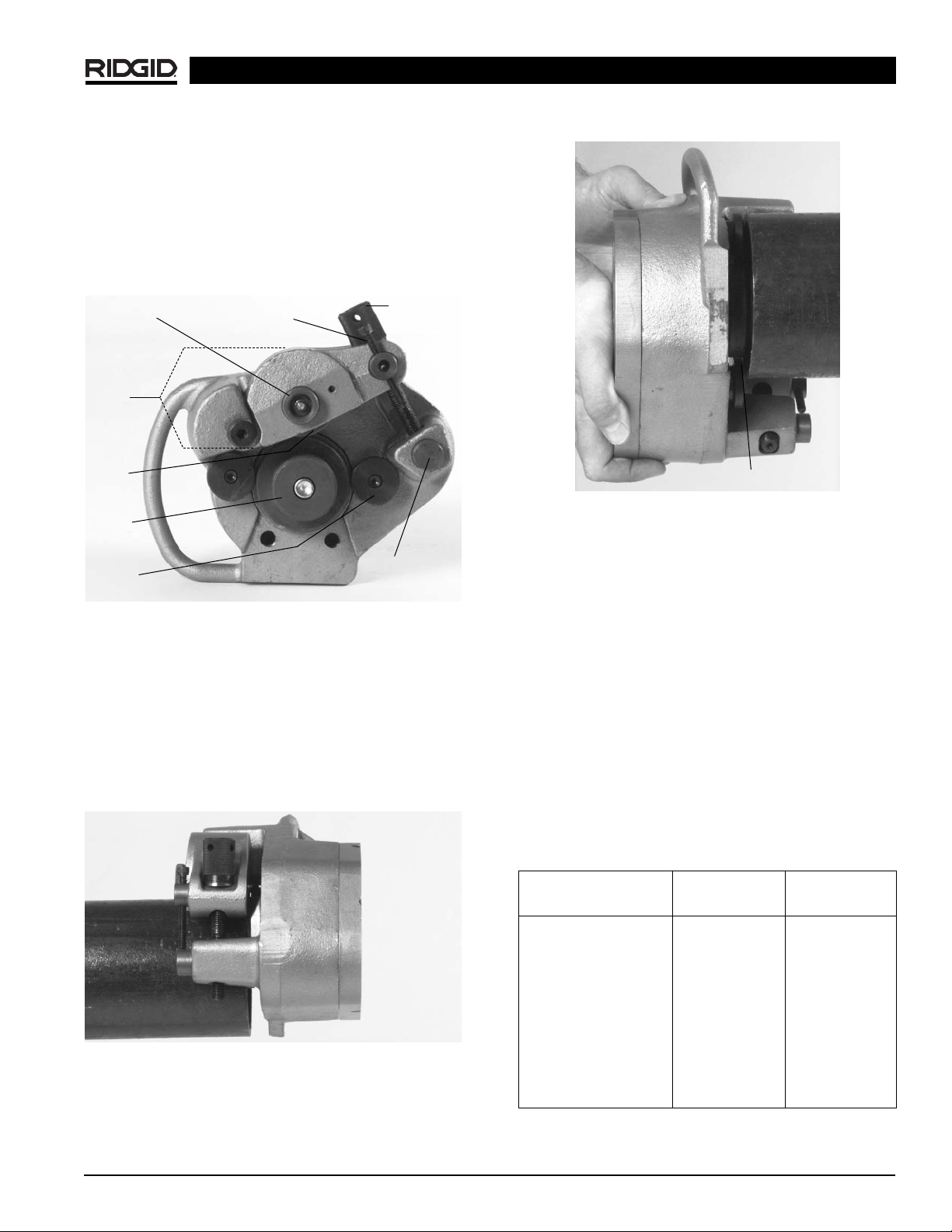
4. The 915 Roll Groover will orbit around the pipe/tube.
Care must be taken that adequate space is provided
completely around material.
NOTE! The RIDGID 915 can roll groove pipe/tube with-
in 31/2″of a wall, ceiling or any other obstruction.
915 In Place Roll Groover
CAUTION
WARNING

Ridge Tool Company 5
915 Roll Groover Set-up
IMPORTANT! To confirm the proper groove depth, test
grooves should be performed and checked
with a Pi tape.
1. At a bench or on the ground, rotate the feed screw
counter clockwise to “open” the groove roll from
the drive roll
(Figure 2)
.
Figure 2 – “Open” Groove Roll from Drive Roll.
NOTE! Ensure that groove set specifications matches
pipe/tube capacity to be grooved. See drive roll
for capacity.
IMPORTANT! Do not attempt to groove copper tube with
the steel groove set. Also do not attempt to
groove steel with copper groove rolls.
2. Place 915 onto pipe/tube with feedscrew accessible
(Figure 3)
.
Figure 3 – Placing Groover on Pipe
3. Push 915 into pipe/tube until fully engaged. End of
pipe should contact the drive roll flange
(Figure 4)
.
Figure 4 – Pipe Contact with Drive Roll Flange
4. Rotate the feed screw clockwise by hand until tight.
915 should now be held in position on the pipe/tube.
Adjusting for Groove Depth
NOTE! The groove depth must be adjusted for each
pipe/tube diameter and wall thickness.
1. With feedscrew handtight, run depth adjustment
screw down until it touches the pivot nut.
2. Back the depth adjustment screw off the number of
turns indicated in
Chart 1 (For Steel/Stainless Steel,
For Copper See Chart 2. These are approximate set-
tings only).
NOTE! The distance between the depth adjustment
screw and the pivot nut equals roll groove depth.
Adjustments up or down, with test grooves, will
ensure proper groove depths for couplings.
Chart 1 – Depth Adjustment for Steel/Stainless Steel
915 In Place Roll Groover
Groove Roll
Shaft Feedscrew
Reaction
Arm
Groove
Roll
Drive
Roll
Stabilizer
Pads Pivot
Nut
Depth
Adjustment
Screw
Drive Roll Flange
Steel/Stainless Steel Sch. 10 Sch. 40
Pipe Diameter Turns Turns
11/4″33/44
11/2″33/44
2″33/44
21/2″43/853/8
3″43/855/8
4″45/867/8
6″57
1/2
8″6N/A
10″61/4N/A
12″71/2N/A

Figure 6 – Grooving pipe
4. Disconnect ratchet from input drive and place in
feedscrew.
5. Tighten feedscrew 1/2turn.
Under or over tightening the feed screw could
result in the 915 “walking” off or slipping inside the pipe.
6. Repeat steps 3 – 5 until depth adjustment screw
touches the pivot nut.
7. Move ratchet from feedscrew to input drive
(Figure 7)
.
Turn ratchet to rotate 915 around pipe/tube two rev-
olutions to complete groove and ensure uniformity.
Figure 7 – Ratchet in Input Drive
Ridge Tool Company
6
Chart 2 – Depth Adjustment for Copper Tubing
NOTE! 1 turn depth setting screw = approximately
.020″change in groove depth (.040 change in
groove diameter).
Forming the Groove
1. Place the ratchet into feedscrew
(Figure 5)
.
Figure 5 – Ratchet in Feedscrew
2. Tighten feedscrew 11/2turns. Be sure pipe is still
flush with drive roll flange.
IMPORTANT! Extreme pressure caused by over ratch-
eting will cause distortion to thin wall pipe.
Do not use power actuated devices
(drills, power drives, impact wrenches, etc.) to drive
the 915 roll groover!
3. Move ratchet from feedscrew to input drive. Turn
ratchet to rotate 915 around pipe/tube one revolution
(Figure 6)
.
915 In Place Roll Groover
WARNING
CAUTION
Cut Tube # of Screw Turns
Size K L M DWV
2″2 2 1.75 N/A
21/2″2 2 1.75 N/A
3″2.25 2.25 2 2
4″3 2.75 2.75 2.5
5″4.25 3.75 3.5 3.25
6″4.75 4 3.75 3.25
8″6.5 4.75 4.25 3.5

4. Remove drive roll from drive shaft.
5. Using a 1/8″hex key, loosen set screw in reaction arm
and remove groove roll shaft
(Figure 9)
.
Figure 9 – Loosening Set Screw in Reaction Arm
6. Remove groove roll and thrust washers from reaction
arm.
Installing New Rollset
1. Place the plain thrust washer at the back of the
reaction arm slot. Place the tabbed thrust washer in
the front of the reaction arm slot with the tab insert-
ed in the small hole to the right of the groove roll
shaft
(Figure 10)
.
Figure 10 – Placement of Thrust Washer
2. Slide groove roll between the thrust washers in the
reaction arm. Be sure that the groove roll is properly
oriented with identification stamping in the “up”
position.
3. Look through the groove roll shaft hole and align the
groove roll and thrust washers with the hole. Insert
groove roll shaft
(Figure 11).
Ridge Tool Company 7
Dismounting the 915 Roll Groover
1. After the roll grooving process is complete, insert
the ratchet onto the feed screw and reverse the
ratchet direction.
2. Rotate the feed screw counter clockwise to release
the pipe from the groove set.
3. Once the groove roll is free from the pipe, slide the
915 off of the pipe.
The 915 will now be free and not support-
ed by the pipe, make sure one hand is supporting the unit
to prevent the 915 from falling.
4. Check groove to see if it is grooved to specification.
See Table 1 or Table 3
for groove specifications.
Removing and Installing
Groove Rolls
1. Separate groove rolls are required when roll grooving
the following:
• 11/4″– 11/2″Schedule 10 and 40 steel
• 2″– 6″Schedule 10 steel
2″– 31/2″Schedule 40 steel
• 4″– 6″Schedule 40 steel
• 8″– 12″Schedule 10 steel
• 2″– 8″ copper tube (Type K, L, M, DWV)
Removing Rollsets for the
Installation of Steel Rollsets
1. Place 915 on table with groove set up.
2. Rotate feedscrew counter clockwise until the reaction
arm is fully retracted.
3. Remove the hex screw retaining the drive roll with a
5/16″hex key
(Figure 8)
. If using the 8″– 12″or 4″– 6″
rollset, remove the drive roll support bolts with a 3/8″
hex key.
Figure 8 – Removing Hex Screw from Drive Roll
915 In Place Roll Groover
WARNING

Ridge Tool Company
8
Figure 11 – Inserting Groove Roll Shaft
4. Tighten set screw in reaction arm with 1/8″hex key to
retain the groove roll shaft.
5. Place drive roll over driveshaft. Be sure that the
drive roll flange contacts the bronze thrust washer.
6. Insert the hex screw into drive roll and tighten with
5/16″hex key.
7. If installing 4″– 6″Schedule 40 or 8″– 12″Schedule
10 drive rolls, install the screws into support housing
and tighten with a 3/8″hex key
(Figure 12)
.
Figure 12 – Installing Drive Rolls
8. If installing 8″– 12″Schedule 10 groove set, using a
3/16″hex key, remove the 2″– 6″stabilizers and
install 8″– 12″stabilizers
(Figure 13)
.
Figure 13 – Installing Stabilizers
Removing Roll Sets for the
Installation of Copper Roll Set
1. Place 915 on table with groove set up.
2. Remove shoulder screw that retains the reaction
arm to the main housing with 1/4″hex key
(Figure 14)
.
Figure 14 – Removing Shoulder Screw
3. Rotate feedscrew counter clockwise until free from
pivot nut and remove reaction arm
(Figure 15).
915 In Place Roll Groover

Ridge Tool Company 9
Figure 15 – Removing Feedscrew
4. Using a 1/8″hex key, remove set screw in reaction
arm and remove groove roll shaft.
5. Remove groove roll and thrust washers from reaction
arm.
6. Remove feedscrew from pivot pin. Remove pivot
pin from reaction arm
(Figure 16)
.
7. Remove the hex screw retaining the drive roll with a
5/16″hex key. If removing the 4″– 6″Sch. 40 or 8″– 12″
Sch. 10 roll set, remove the drive roll support bolts
using a 3/8″hex key
(Figure 16)
.
8. Remove stabilizer pad on the handle side of the 915
using a 3/16″hex key. If removing the 8″– 12″Sch. 10
roll set remove both stabilizer pads
(Figure 16)
.
Figure 16 – Parts Call Out
Installing Copper Roll Set
1. Install copper stabilizer pad on handle side of 915
groover using the 3/16″hex key (Opposite side stabilizer
should be standard 2″– 6″Sch. 10 stabilizer pad.)
(Figure 17)
.
Figure 17 – Installing Copper Stabilizer Pad
2. Place the copper drive roll over driveshaft. Be sure
that the drive roll flange contacts the bronze thrust
washer.
3. Insert the hex screw into the drive roll and tighten with
5/16″hex key.
4. Using the copper reaction arm (painted black), place
the plain thrust washer at the back of the reaction arm
slot. Place the tabbed thrust washer in the front of the
reaction arm slot with the tab inserted in the small
hole to the right of the groove roll shaft
(Figure 18)
.
Figure 18 – Inserting Tabbed Thrust Washer
5. Slide the groove roll between the thrust washers in
the reaction arm. Be sure that the groove roll is
properly oriented with the identification stamping in
the “up” position.
6. Look through the groove roll shaft hole and align
the groove roll and thrust washers with the hole.
Insert groove roll shaft.
915 In Place Roll Groover
Reaction Arm
Feedscrew
Pivot Nut
Tabbed Thrust Washer
Plain Thrust Washer
Groove
Roll Shaft
Groove
Roll
Handle
Side
Stabilizer
Pad

7. Install the set screw into the reaction arm and tighten
with 1/8″hex key to retain the groove shaft.
8. Install the pivot pin into the copper reaction arm
making sure the flat is in the “up” position so that it
will accept the thrust washer and the head of the
feedscrew
(Figure 19)
.
Figure 19 – Pivot Pin Position
9. Insert the copper reaction arm into the slot in the
main housing and install the shoulder screw. Tighten
with 1/4″hex key.
10. Thread the feedscrew clockwise into the pivot nut.
Accessories
WARNING
Only the following RIDGID products have been
designed to function with the 915 Roll Groover.
Other accessories designed for use with other
tools may become hazardous when used on this
Roll Groover. To prevent serious injury, use only
the accessories listed below.
Accessories for 915 Roll Groover
•Roll Set for 11/4″– 11/2″Sch. 10/40 Steel pipe
•Roll Set for 4″– 6″Sch. 40 Steel pipe
•Roll Set for 8″– 12″Sch. 10 Steel pipe
•Roll Set for 2″– 8″Copper Tube Types K, L, M,
DWV
•Carrying Case for 915 Groover and Roll Sets
NOTE! A Roll Set consists of a Groove Roll and a
Drive Roll.
Maintenance Instructions
Lubrication with Lithium Base Grease
•Add grease to the fitting on the back cover until a
small amount is seen at bronze thrust washer at
front of unit.
•Add grease to fitting in the groove roll shaft until a
small amount is seen at the side of groove roll.
•Lubricate the feedscrew and thrust washer.
Groove or Drive Rolls Maintenance
•Keep groove rolls clean. Use a wire brush to remove
debris.
•Keep feedscrew clean.
•Inspect groove and drive rolls and replace if worn or
damaged.
Ridge Tool Company
10
915 In Place Roll Groover
Tool Storage
WARNING Store the tool in a locked area that is out
of reach of children and people unfamiliar with roll
groover equipment. This tool can cause serious injury in
the hands of untrained users.
Service and Repair
WARNING
Service and repair work on this Roll Groover must be
performed by qualified repair personnel. Tool should
be taken to a RIDGID Independent Authorized Service
Center or returned to the factory. All repairs made by
Ridge service facilities are warranted against defects in
material and workmanship.
When servicing the Groover, only identical replacement
parts should be used. Failure to follow these instructions
may create a risk of serious injury.
Pivot Pin
Flat

Ridge Tool Company 11
915 In Place Roll Groover
TA B C D
NOM. PIPE MIN. GASKET GROOVE GROOVE NOM.
PIPE DIAMETER WALL SEAT WIDTH DIAMETER GROOVE
SIZE O.D. TOL. THK. +.015/-.030 +.030/-.015 O.D. TOL. DEPTH (Ref.)2
11/41.660 +.016 .065 .625 .281 1.535 +.000 .063
-.016 -.015
11/21.900 +.016 .065 .625 .281 1.775 +.000 .063
-.016 -.015
2 2.375 +.024 .065 .625 .344 2.250 +.000 .063
-.016 -.015
21/22.875 +.030 .083 .625 .344 2.720 +.000 .078
-.018 -.015
3 3.50 +.030 .083 .625 .344 3.344 +.000 .078
-.018 -.015
31/24.00 +.030 .083 .625 .344 3.834 +.000 .083
-.018 -.015
4 4.50 +.035 .083 .625 .344 4.334 +.000 .083
-.020 -.015
5 5.563 +.056 .109 .625 .344 5.395 +.000 .084
-.022 -.015
6 6.625 +.050 .109 .625 .344 6.455 +.000 .085
-.024 -.015
8 8.625 +.050 .109 .750 .469 8.441 +.000 .092
-.024 -.020
10 10.75 +.060 .134 .750 .469 10.562 +.000 .094
-.025 -.025
12 12.75 +.060 .156 .750 .469 12.531 +.000 .110
-.025 -.025
Table I. Standard Roll Groove Specifications1
NOTE! All Dimensions are in Inches.
1. As per AWWA C606-87.
2. Nominal Groove Depth is provided as a reference dimension. Do not use groove depth to determine groove acceptability.

Ridge Tool Company
12
915 In Place Roll Groover
Table III. Copper Roll Groove Specifications
1 2 345678
AB CDT
Nom. Tubing Outside Gasket Groove Groove Groove Min. Max.
Size Diameter O.D. Seat Width Dia. Depth Allow. Allow.
Inches A +.03 +.00 Ref.1Wall Flare
Basic Tolerance ±0.03 –.000 –.02 Thick. Dia.
2″2.125 ±0.002 0.610 0.300 2.029 0.048 0.064 2.220
21/2″2.625 ±0.002 0.610 0.300 2.525 0.050 0.065 2.720
3″3.125 ±0.002 0.610 0.300 3.025 0.050 DWV 3.220
4″4.125 ±0.002 0.610 0.300 4.019 0.053 DWV 4.220
5″5.125 ±0.002 0.610 0.300 5.019 0.053 DWV 5.220
6″6.125 ±0.002 0.610 0.300 5.999 0.063 DWV 6.220
8″8.125 +0.002/-0.004 0.610 0.300 7.959 0.083 DWV 8.220
Table II. Pipe Maximum and Minimum Wall Thickness
NOTE! All Dimensions are in Inches.
CARBON STEEL OR STAINLESS STEEL
ALUMINUM PIPE OR TUBE PIPE OR TUBE PVC PIPE
Pipe Size Wall Thickness Wall Thickness Wall Thickness
Min. Max. Min. Max. Min. Max.
11/4″.065 .140 .065 .140 .140 .140
11/2″.065 .145 .065 .145 .145 .200
2″.065 .154 .065 .154 .154 .154
21/2″.083 .203 .083 .188 .203 .276
3″.083 .216 .083 .188 .216 .300
31/2″.083 .226 .083 .188 .226 .226
4″.083 .237 .083 .188 .237 237
5″.109 .258 .109 .188 .258 .258
6″.109 .280 .109 .188 .280 .280
8″.109 .148 .109 .188 — —
10″.134 .165 .134 .188 — —
12″.156 .180 .156 .188 — —
1. Nominal Groove Depth is provided as a reference dimension. Do not use groove depth to determine groove acceptability.

Ridge Tool Company 13
915 In Place Roll Groover
Troubleshooting
Incorrect size of Grooving and Driving Rolls
Mismatched Grooving and Driving Rolls
Grooving Roll and/or Driving Roll worn
Pipe length not straight
Pipe end not square with pipe axis
Driving Roll knurl plugged or worn
Feed Screw not tight
Turning Ratchet wrong direction
Inside of pipe has too much scale
Pipe end flattened or damaged
Hard spots in pipe material or weld seams harder
than pipe
Grooving Roll feed rate too slow
Pipe wall maximum thickness exceeded
Wrong rolls
Pipe material too hard
Adjustment screw not set
Maximum pipe diameter tolerance exceeded
Mismatched Grooving and Driving Rolls
Depth adjustment screw not set correctly
Grooving force too low
Driving Roll knurling plugged with metal or worn
flat
Install correct size of Grooving and Driving Rolls
Match Grooving and Driving Rolls
Replace worn Roll
Use straight pipe
Cut pipe end square
Clean or replace drive roll
Tighten feed screw with ratchet for every
revolution as per directions
Turn Ratchet in proper direction
Clean inside of pipe
Cut off damaged pipe end
Hand feed Grooving Roll into pipe faster
Check pipe capacity chart
Install correct rolls
Replace pipe
Set depth
Use correct diameter pipe
Use correct set of Rolls
Adjust depth setting
Tighten feed screw
Clean or replace Driving Roll
PROBLEM CAUSE SOLUTION
Rolled Groove too nar-
row or too wide
Rolled Groove not per-
pendicular to pipe axis
915 will not track while
grooving
915 rocks from side to
side on Driving Roll
while grooving
915 Groover will not roll
groove pipe
915 Groover will not roll
groove to required
diameter
Pipe slips on Driving
Roll

Printed in U.S.A. 11/12 999-998-025.10
EC39404 REV. A
99 Washington Street
Melrose, MA 02176
Phone 781-665-1400
Toll Free 1-800-517-8431
Visit us at www.TestEquipmentDepot.com
Table of contents
Other RIDGID Tools manuals

RIDGID
RIDGID RT1000 User manual

RIDGID
RIDGID K-45 User manual

RIDGID
RIDGID SeekTech SR-24 User manual

RIDGID
RIDGID RP 115 User manual

RIDGID
RIDGID SeeSnake STANDARD User manual

RIDGID
RIDGID AC2030 User manual

RIDGID
RIDGID R01701 User manual

RIDGID
RIDGID JobMax R8223401 User manual

RIDGID
RIDGID MegaPress User manual

RIDGID
RIDGID RE 6 User manual

RIDGID
RIDGID JobMax A Series User manual

RIDGID
RIDGID CM1400 User manual

RIDGID
RIDGID RE 6 User manual

RIDGID
RIDGID 206 User manual

RIDGID
RIDGID 918 User manual

RIDGID
RIDGID 815A NPT User manual

RIDGID
RIDGID K-40 User manual

RIDGID
RIDGID SeeSnake nanoReel User manual

RIDGID
RIDGID HKO-186 User manual

RIDGID
RIDGID HB382 User manual