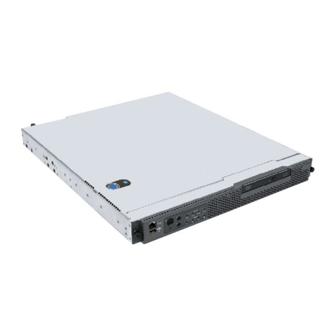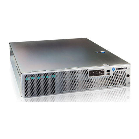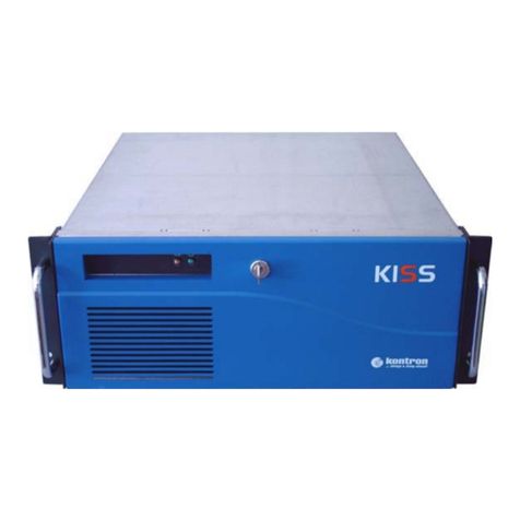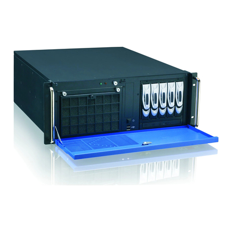
ZINC CUBE C232 - Rev. 1.0
www.kontron.com // 10
Table of Contents
Symbols.................................................................................................................................................................................................................6
For Your Safety ...................................................................................................................................................................................................7
High Voltage Safety Instructions ..................................................................................................................................................................7
Special Handling and Unpacking Instruction ............................................................................................................................................7
Lithium Battery Precautions.......................................................................................................................................................................... 8
General Instructions on Usage..................................................................................................................................................................... 8
Quality and Environmental Management................................................................................................................................................ 8
Disposal and Recycling.................................................................................................................................................................................... 8
WEEE Compliance.............................................................................................................................................................................................. 8
Table of Contents.............................................................................................................................................................................................10
List of Tables .....................................................................................................................................................................................................12
List of Figures....................................................................................................................................................................................................12
1/ Specifications and Regulatory information .............................................................................................................................14
1.1. European Union Regulatory Notice......................................................................................................................................................14
2/ Component Identification ...............................................................................................................................................................15
2.1. Front Panel Components........................................................................................................................................................................16
2.2. Rear Panel Components.........................................................................................................................................................................17
2.3. Storage Drive LEDs...................................................................................................................................................................................17
2.4. Board LEDs .................................................................................................................................................................................................18
2.4.1. RJ45 ............................................................................................................................................................................................................18
2.5. System Board Components..................................................................................................................................................................20
2.6. System Components ...............................................................................................................................................................................21
3/ Operations ...........................................................................................................................................................................................23
3.1. Powering up the Server..........................................................................................................................................................................23
3.2. Powering down the Server...................................................................................................................................................................23
3.2.1. Shutting down the Server ..................................................................................................................................................................23
4/ Installation ..........................................................................................................................................................................................24
4.1. Safety Measures ......................................................................................................................................................................................24
4.2. Identifying the Contents of the Server Shipping Carton ............................................................................................................24
4.3. Front Panels..............................................................................................................................................................................................25
4.4. Hard Disk Drives ......................................................................................................................................................................................26
4.5. Installing a 3.5" HDD Module ............................................................................................................................................................... 27
4.6. Removing a 3.5" HDD Module..............................................................................................................................................................28
4.7. Installing a 2.5" HDD module ...............................................................................................................................................................29
4.8. Removing a 2.5" HDD module..............................................................................................................................................................30
4.9. Top Cover ....................................................................................................................................................................................................31
4.9.1. Removing a top Cover ..........................................................................................................................................................................31
4.9.2. Installing a top Cover.......................................................................................................................................................................... 32
4.10. Solid State Drives ..................................................................................................................................................................................33
4.10.1. Removing an SSD Module................................................................................................................................................................ 33
4.10.2. Installing an SSD Module ................................................................................................................................................................34
4.11. System Board Trays .............................................................................................................................................................................. 35
4.11.1. Removing a System Board Tray...................................................................................................................................................... 35
4.11.2. Installing a System Board Tray......................................................................................................................................................36
4.12. Rear Plates............................................................................................................................................................................................... 37
4.12.1. Removing a Rear Plate...................................................................................................................................................................... 37


