Kopron KDF-M Quick setup guide

DOCK SEALS
LOGISTIC
SOLUTIONS
ASSEMBLY, USE AND
MAINTENANCE MANUAL
MOD. KDF-M

Assembly, use and maintenance manual
3
INTROD CTION
NIT I DESCRIPTION
NIT II IDENTIFICATION AND CONTROL
OF THE MATERIAL
NIT III VERIFICATION OF THE MASONRY WORK
NIT IV INSTR CTIONS
NIT V ENVIRONMENT POLL TION
NIT VI SPARE PARTS
NIT VII SERVICE / G ARANTEE
GENERAL INDEX

Assembly, use and maintenance manual
4
INT ODUCTION
UNIT I - DESC IPTION
CHAP. 1
1.1 DESC IPTION OF AISED DOCK SHELTE S
1.2 IMP OPE USE
1.3 IDENTIFICATION PLATE
UNIT II -IDENTIFICATION AND CONT OL OF THE MATE IAL
CHAP. 1
1.1 P EAMBLE
1.2 IDENTIFICATION AND CONT OL OF THE MATE IAL
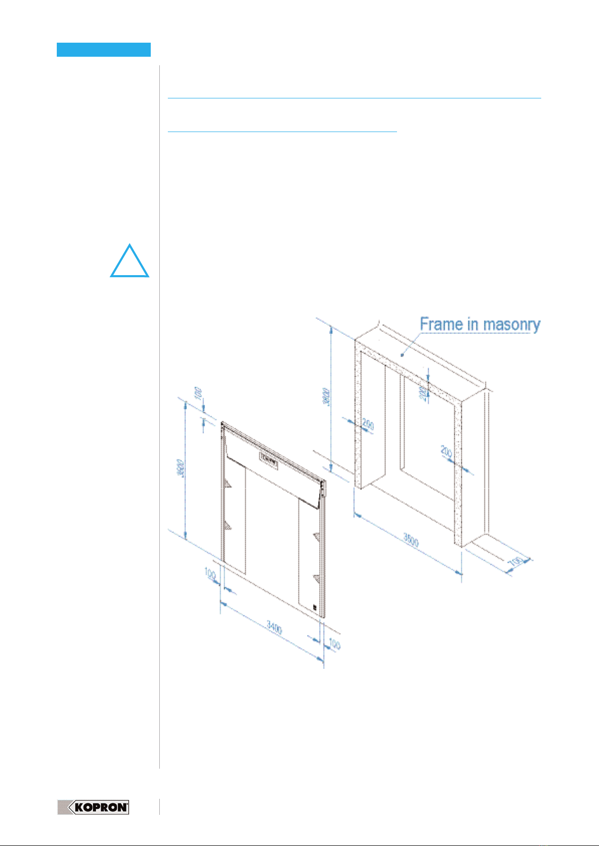
UNIT III - VE IFICATION OF THE MASON Y WO K
CHAP. 1
1.1 VE IFICATION OF THE MASON Y WO K
UNIT IV - INST UCTIONS
CHAP. 1- INST UCTIONS FO T ANSPO T
1.1 GENE AL INDICATIONS
1.2 HANDLING INST UCTIONS
CHAP. 2 – INSTALLATION
2.1 BEFO E STA TING
2.2 F ONT SEAL ASSEMBLY
2.3 POSITIONING AND FIXING
2.3.1 NOTE ON THE USE OF THE ANCHO BOLTS
2.4.ASSEMBLY OF THE ELASTIC CO D
2.5 LIST OF TOOLS AND EQUIPMENT
2.6 EMOVAL OF EXCEEDING MATE IAL
2.7 ENVI ONMENT CONDITIONS
CHAP. 3 - USE
3.1 ISKS AND P OTECTION
3.2 FI E P EVENTION
CHAP. 4 - ANOMALIES, MAINTENANCE AND EPAI
4 1 P EVENTIVE MAINITENANCE AND PLANNED INSPECTIONS
4.2 NOTES ON THE EQUIPMENT TO USE
CHAP. 5 - INST UCTIONS ON SAFETY
5.1 OTHE ISKS
5.2 MAINTENANCE INST UCTIONS
UNIT V -ENVI ONMENT POLLUTION
CHAP. 1 -
1.1 DISPOSAL AND DISMANTELLING
UNIT VI - SPA E PA TS
CHAP. 1 –
1.1 SPA E PA TS.
UNIT VII – SE VICE / GUA ANTEE
CHAP. 1
1.1 P OCEDU ES TO EQUEST ASSISTANCE
1.2 TE MS AND CONDITIONS FO INTE VENTIONS UNDE GUA ANTEE
All drawings and technical characteristics may be subject to changes at any time,
should this occur we shall provide to update the manual as soon as possible.
Kopron S.p.A.
page 5
7
8
8
9
9
11
12
12
13
14
15
17
18
19
19
19
20
20
21
21
22
23
24
24
26
27
S MMARY

Assembly, use and maintenance manual
5
This manual is a guide for installers, users and maintenance personnel as well as
being useful for preventing accidents during life cycle of the equipment from instal-
lation to dismantling.
In case instructions are not clear or should particular problems arise and are not men-
tioned herein, please apply to our service department. Do not take personal initiati-
ves for interventions if instructions are not fully understood.
Buyer and personnel involved in installation should read this manual before using the
equipment. We would suggest to keep a copy of this manual handy in a place where
it can be easily consulted.
Assembly and installation must be carried out by qualified personnel adequately
equipped to operate in absolute safety condition. A dedicated chapter on risks will
face the matter in detail.
Preventive maintenance for solving anomalies must be programmed according to
regulations which require only specialized personnel to carry out interventions.
To have another copy of the manual you may contact our service department at the
following address:
S.p.A.
via Primo Maggio s.n.
20064 Gorgonzola – Milan - Italy
+39 - 02 – 921 52. 1
KOP ON S.p.A. have the right to update or improve the manual without affecting the
validity of this version.
Some important points have been highlighted by using symbols explained on next
page.
INTROD CTION

Assembly, use and maintenance manual
6
SYMBOLS
DANGER - NOTICE
This sign indicates serious danger which must not be under estimated in order not
to risk people’s health and safety.
CA TION
This sign indicates the requiement to be careful on how to move and act in order not
to risk people’s health and safety and cause economical damages
IMPORTANT
This sign indicates technical information and important regulations to pay attention
to.
ECOLOGY
Remarks regarding ecology
PROHIBITION
If instructions contained in this manual are not strictly followed and original spare
parts are not used, or in case ordinary maintenance or non authorized interven-
tions are carried out Buyer will take his own responsabilities and guarantee will no
longer be valid.
Kopron S.p.A.
INTROD CTION
!

Assembly, use and maintenance manual
7
CHAPTER 1
DESCRIPTION
1.1 DESCRIPTION OF DOCK SEALS
Dock seals are particularly suitable for limiting temperature variation between inside
and outside of the building during loading/unloading operations.
There use allows energy saving when either heating or airconditioning is functioning
inside the building.
This model can meet general requirements and besides being of high quality it is also
economical.
Dock seals are usually assembled to seal the door space at the height of a raised
dock leveller on a frame in masonry usually prefabricated.
The carrying frame is anchored to the masonry frame.
All the metal parts of the structure are in hot-galvanized steel sheet.
Flaps subject to rubbing of the trucks are in thick, special weft, anti-scratching PVC,
with a double layer of tear resistant fabric enable to bear bendings and torsions.
The side flaps are marked with arrows indicating the correct positioning of the lorry.
The flaps are in a class 2 self-extinguishing fabric.
External dimensions of the front seal are: Width 3.400 mm, Height 3.500 mm.
Dimensions of the masonry frame:
NIT I DESCRIPTION

Assembly, use and maintenance manual
8
NIT I DESCRIPTION
1.2 IMPROPER SE
The front seals with fixed cushions have been specifically designed with the aim to
create a division between the outside of a building and the inside, by adhering to the
truck during loading/unloading operations.
They cannot have a different application.
In case Buyers need to use them differently they must inform Kopron S.p.A. who in
case of authorization will suggest how to handle the product in the best way.
Improper use, and ignoring the instructions contained in this manual will imply
Buyer to take his own responsabilities and guarantee will no longer be valid.
1.3 IDENTIFICATION PLATE
An identification plate is positioned permanently on the right flap as shown in the
enclosed drawing.
The data on identification plate must always be kept clean and legible.
The aim of this identification plate is to identify the dock shelter and becomes neces-
sary when the quantity of dock shelters is considerable. Kopron S.p.A. reserves the
right to decide when it is the case to apply this identification plate.
Should it be ruined and become no longer legibile it must be replaced.
In the request you must mention the model, year of manufacturing and serial num-
ber, data which can be easily found in the documents delivered along with the dock
shelter.

Assembly, use and maintenance manual
9
CHAPTER 1
IDENTIFICATION AND CONTROL OF THE MATERIAL
1.1 PREAMBLE
Each shipment of dock shelters is made of one or more packages, in case of
multiple orders, already placed on pallets. Max size for each package is mm 1.100 x
3.600 x height 1.300.
Each package can reach max 800 kgs.
Material contained in the packages is wrapped in plastic sheets.
All packages have a label carrying the order number.
In case of supply and delivery of more than one dock shelter it could happen to have
the coverings all in one package.
uts, bolts and elastic strings can also be packed all together in one package.
To verify the completeness of the supply we suggest to check all the packages.
If packages are to be stored, the warehouse must be sheltered and dry.
Packages must not be placed one on top of the other in order to avoid damages.
Take care not to damage the PVC fabric when cutting the plastic wrappings.
1.2 IDENTIFICATION AND CONTROL OF THE MATERIAL
Transport documents accompanying the delivery of the dock shelter also include a
list of material.
Upon receipt the material must go through inspection with the aid of the packing list
to verify completeness. In case of damages or missing items, written claim must be
made within seven days from delivery and sent through registered mail to Kopron
S.p.A.
See drawing enclosed to better identify the details listed in the packing list.
NIT II IDENTIFICATION AND CONTROL OF THE MATERIAL

Assembly, use and maintenance manual
10
LIST OF COMPONENTS
NIT II IDENTIFICATION AND E CONTROL OF THE MATERIAL
Top flap
Right flap
Left flap
1
2
3
1
2
5
4
LEGEND
Fixing profiles
Eastic strings
4
5
4
3

Assembly, use and maintenance manual
11
CHAPTER 1
VERIFICATION OF THE MASONRY WORK
1.1 VERIFICATION OF THE MASONRY WORK
Before starting assembly you must check if the masonry work size is compatible with
the dock seal.
Make sure that the external width and height of framework do not prevent the
installation.
Length and height of the dock seal are indicated in the drawing.
Make sure that bolts do not interfere with the electric cables, gas tubes, water
pipelines.
Eventually you may use specific devices for detecting hidden cables.
Contact with electric lines can cause fire or electric shocks.
Damaged gas tubes create high risk of explosion.
Perforated water pipelines can cause either damages to the material and/or electric
shocks.
Verify with a technician of the Buyer that the carrying structure is suitable to bear the
weight of the dock shelter and the stress caused during working.
This verification must be carried out by a specialist. For any further problem you may
apply to the Service Dpt in Kopron S.p.A. referring to the data contained in the tran-
sport documents: +39- 02 – 92 152 .1
NIT III VERIFICATION OF THE MASONRY WORK
!

Assembly, use and maintenance manual
12
CHAPTER 1
INSTR CTIONS REGARDING TRANSPORT
1.1 GENERAL INDICATIONS
The handling of the material, must be assigned to personnel trained to operate
forklifts or other machinery used for lifting material
Safety measures must be undertaken to guarantee the stability of the machine and
of the material.
Should the forklift operator be unable to control the way during handling of goods
another person he must go before him and help.
ecessary conditions for lifting material is the perfect balancing of the goods.
The machinery used must be suitable to the volumes and weights to handle.
During operations you must keep an adequate speed and avoid swinging of the
material.
Do not leave for any reason the forklift with the material in lifted position. In case of
interruption of manoeuvres always lower the goods.
1.2 HANDLING INSTR CTIONS
Each shipment of dock shelters is made of one or more packages in case of
multiple orders, already placed on pallets. Max size for each package is mm 1.100 x
3.600 x height 1.300.
Each package can reach max 800 kgs.
Material contained in the packages is wrapped in plastic sheets.
The transport and handling of material must be by means of a forklift.
Forks must work as shown in the drawing.
o cranes must be used, bridle slings around the package would cause damages
inside.
Packages must not be placed one on top of the other in order to avoid damages.
If packages are to be stored, the warehouse must be sheltered and dry.
Take care not to damage the material when cutting the plastic wrappings.
NIT IV INSTR CTIONS
!

Assembly, use and maintenance manual
13
CHAPTER 2
INSTALLATION ASSEMBLY
2.1 BEFORE STARTING
Along with the delivery of material you may have, upon request, an envelope with
drawings and technical data regarding the supply, which in addition to the instruc-
tions contained in this manual are an aid for an easy, correct and safe assembly of
the dock seals.
The envelope can also contain information regarding the positioning of the dock shel-
ter and other details on the technical/commercial agreement between Buyer and
Kopron S.p.A.
Therefore, do not start assembly before having read the contents of the envelope.
In case of doubts please apply to the Service Dpt in Kopron S.p.A. at the following
numbers, referring to the order number visible on the packages:
+39 -02 -92 152 .1
Assembly must be carried out according to local regulations in force and by specia-
lized and skilled personnel.
Specialized personnel, in charge of the assembly, must be informed in advance about
the work to be done, the risks they may face in order to provide necessary tools and
take the measures for safety.
Assembly must not be carried out in strong windy days.
A scaffold must be positioned near the wall where the dock shelter is going to be
assembled.
Before beginning work mark off the working area by means of a white/red ribbon
usually used in building yards.
NIT IV INSTR CTIONS
!

Assembly, use and maintenance manual
14
2.2 ASSEMBLY OF THE FRONT SEAL
Lay on the floor the wooden bars and start assembling the front seal by using the
profiles and eight hexagonal head screws M 10 X 50.
Fix jambs to the cross member by fastening the screws making sure the jambs are
parallel. The parallel positon of the jambs can be checked by measuring the diago-
nals which must be equal.
NIT IV INSTR CTIONS
Please note that the frame of the front seal is in galvanized steel sheet, any opera-
tion which could scratch off the protective coating, such as welding and grinding
which are the most common, must be avoided.
Protective coating is important to prevent corrosion.

Assembly, use and maintenance manual
15
2.3 POSITIONING AND FIXING
Once the front seal has been assembled it must be lifted and leaned against the wall
and fixed.
This operation must be carried out with the aid of a forklift and a pallet to be positio-
ned under the front cross member.
Then it must be lifted slowly taking care not to strain the jambs which must accom-
pany the lifting movement.
The pallet is necessary as a further support along with the cross members and helps
to prevent the front seal to be stressed during lifting and positioning operations.
Use a pallet in good conditions, and take care to pad with polystyrene or similar
material points of contact or edges which could damage the flaps.
Once the front seal has been postioned, start fixing it after having checked the
vertical position of the jambs and the perfect spirit levelling of the cross members.
Check the jambs are parallel by measuring the diagonals which must be equal.
Dowel the front seal as shown in the drawing.
NIT IV INSTR CTIONS

Assembly, use and maintenance manual
16
NIT IV INSTR CTIONS

Assembly, use and maintenance manual
17
NIT IV
2.3.1 NOTES ON THE SE OF ANCHOR BOLTS
INSTR CTIONS
Anchoring length 120 mm
Certifications ETA, Fire (IBMB and Warrington)
Basic material concrete block (solid, intact)
Environment conditions Inside dry
Type of anchoring Mechanical
Functioning principle Torque controlled expansion
Type of fixing Through-fastening, Pre-setting
Material Straight-carbon steel
Material coating Galvanized min. 5µm
Identific. length mark G
Minimum penetration depth 50 mm
-empty brick
Max diam. passing hole 12 mm
Insert diameter 10 mm
couple requested 30 m
Key size 17 mm
Total length 120 mm
Diam. thread (M) M10
Protection from corrosion Zinc plated to min. 5µm
ASSEMBLY
Drill hole with insert Ø 10, depth of the hole 110 mm.
Make sure the hole is clean before inserting the anchor bolts.
Anchor Bolts HILTI tipo HSA M 10 x 120. Articolo: 00255842

Assembly, use and maintenance manual
18
2.4 ASSEMBLY OF THE ELASTIC STRINGS
The elastic string for pulling the side panels must be assembled for last once the front
seal has already been fixed to the wall.
The string is supplied as in ref. 1, with three metal hooks, two at the two ends and
one free.
The free hook must be stopped at half a string with a knot as shown at ref. 2.
To assemble the string you must hook the central hook (the one stopped with the
knot) to the hole positioned at the center of the cross member of the front arch, and
the two other hooks (at the ends of the cord) must be hooked to the loops of the side
flaps.
NIT IV INSTR CTIONS
1
2
Cross member central hole
Side lap loops
Carrying arch of the front part
5
LEGEND
3
4
4
4
4
5
3
fixed knot

INSTR CTIONS
Assembly, use and maintenance manual
19
NIT IV
2.5 LIST OF TOOLS AND EQ IPMENT
In order to carry out installation with ease and in safety the following tools and equip-
ment may be used:
Plumb line, wire for tracing, pencils, laser level, level and ruler of about 2 m
Drill complete with inserts for drilling iron.
Churn drill complete with inserts for reinforced concrete.
Saw for metal with set of blades.
Clamps and trestles
Control panel and sockets suitable for building yards, complete with general switch,
thermal magnetic switch and differential set at 30 mA.
Extension wires with sockets and plugs, for single phase supply 230 V and three
phase 400 V.
Fixed ladder 2.5 m long provided with movable elements for reaching a further
extension of 6 m.
Wheeled scaffold with a height which reaches the dock.
Tool box with keys, screwdrivers, pliers, hammers, etc...
Safety tools,safety belts, goggles, helmets, protection gloves against cuts and scrat-
ches, safety shoes, opto-isolators.
First aid box
The assembly area must be delimited by a red and white striped ribbon normaly used
in building yards.
All tools and equipment must be according to EC safety standards.
2.6 REMOVAL OF EXCEEDING MATERIAL
Exceeding and waste material from assembly can be dumped along with Customer’s
waste material.
2.7 ENVIRONMENT CONDITIONS
For a correct functioning of the dock shelter minimum and maximum temperatures
depend on the technical characteristics of the covering sheet and on the PVC of the
front flaps, therefore it cannot operate under 15°C and over 50° C.
Should it be necessary to operate with different temperatures please apply for info
and support to our Service Dpt.

Assembly, use and maintenance manual
20
NIT IV
CHAPTER 3
SE
3.1 PARTIC LAR RISKS AND SPECIFIC PROTECTION
There are no dangerous spots near the front seal and operator can move at ease.
He must however avoid either staying or getting near to the front seal when lorry is
in loading/unloading phase, or stop under the front seal.
Vehicles must approach and dock according to regulations established by user for
the safety of personnel.
3.2 FIRE-PREVENTION
Dock seals can be installed in areas without particular fire-prevention methods.
However please note that covering panels are in self-extinguishing, class 2 PVC.
INSTR CTIONS

INSTR CTIONS
Assembly, use and maintenance manual
21
NIT IV
CHAPTER 4
ANOMALIES, MAINTENANCE AND REPAIR
4.1 PREVENTIVE MAINTENANCE AND PLANNED INSPECTIONS
Weekly inspection
Verify if the carrying arch tubulars are in good conditions.
Check the fastening of the anchor bolts.
Check the fastening of the nuts and bolts assembling the archs.
Check the condition of the elastic strings
Quarterly inspection
Check status and efficiency of the closing panels.
Cleaning and brushing of the panels.
Annual inspection
Fastening of the dock seal anchor bolts
Fastening of the door anchor bolts
Inspection and controls, or operational interventions must be carried out by specia-
lized personnel with proven skills as according to norm E 292.2 art. 5.5.1.
4.2 NOTE ON THE EQ IPMENT TO SE
ormal workshop equipment is sufficient to carry out all maintenance and repair ope-
rations of the door.
There is no need of special tools and equipment.
Table of contents
Other Kopron Shelter manuals
Popular Shelter manuals by other brands

TMG
TMG TMG-1220RST product manual

No Butts Bin
No Butts Bin SR1559-F Assembly instructions

Globel
Globel 6' Wide Assembly instructions

ShelterLogic
ShelterLogic 62656 Assembly instructions

Shelters4Less
Shelters4Less SR0059-01-160117 Assembly instructions

Vikre Handel AS
Vikre Handel AS JIT-2326J Assembly manual

No Butts Bin
No Butts Bin SR1562-F Assembly instructions

NBB
NBB SR8299 Assembly instructions

Haws
Haws 9035 Installation, operation & maintenance instructions

Kiwi Camping
Kiwi Camping Savanna 4 Ezi-Up Pitching instructions

Hardlife Utility
Hardlife Utility C2020 instruction manual

Sojag
Sojag Luxor owner's manual