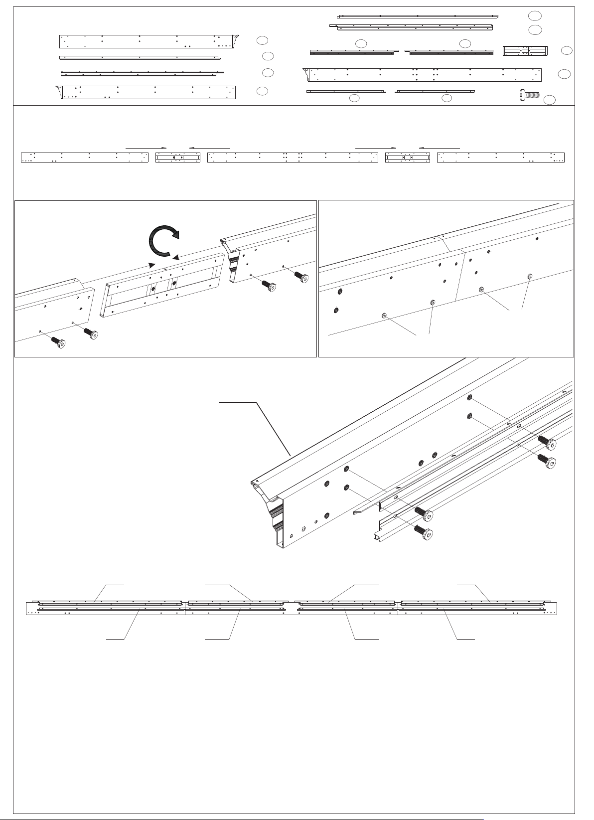
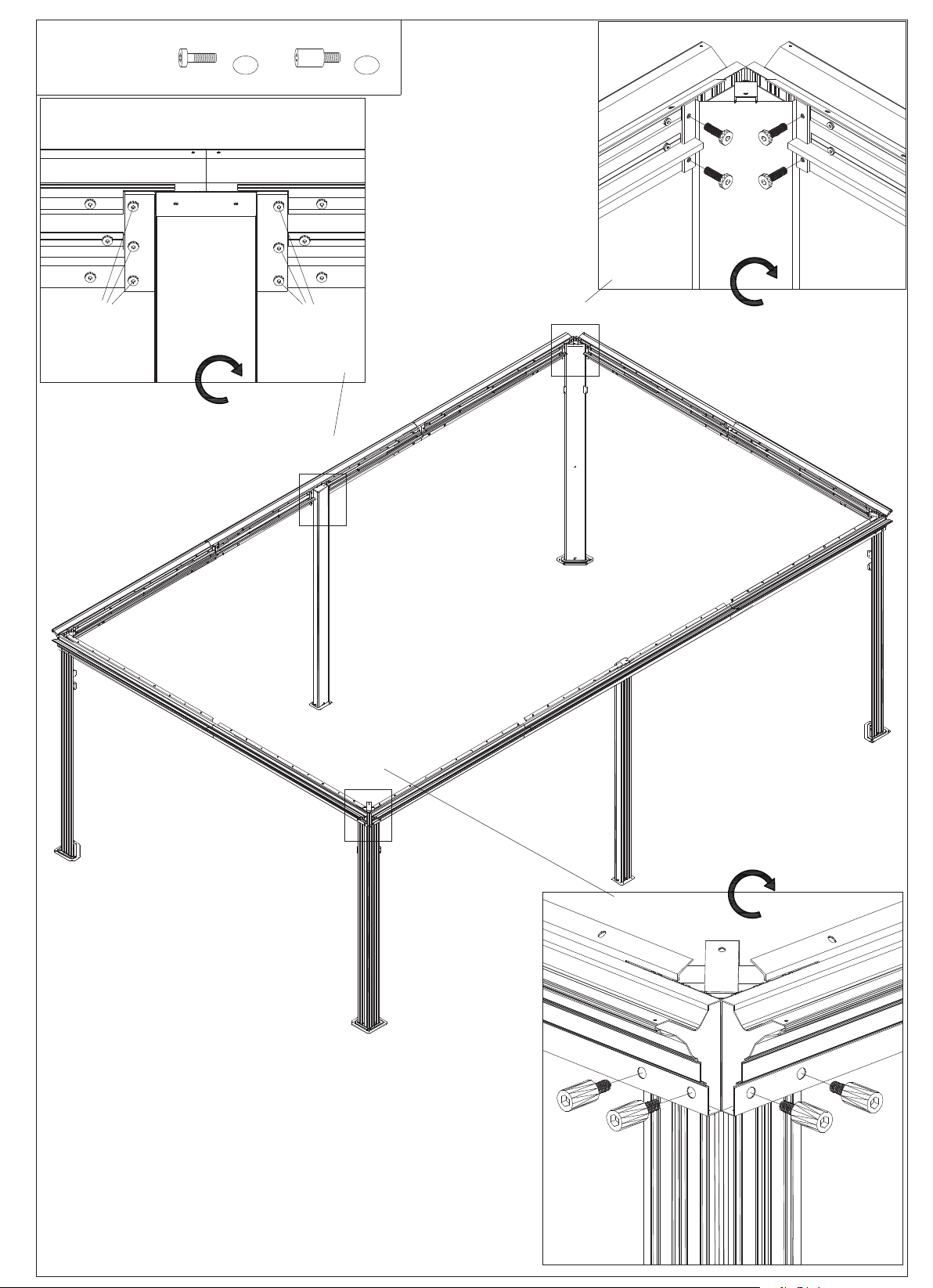
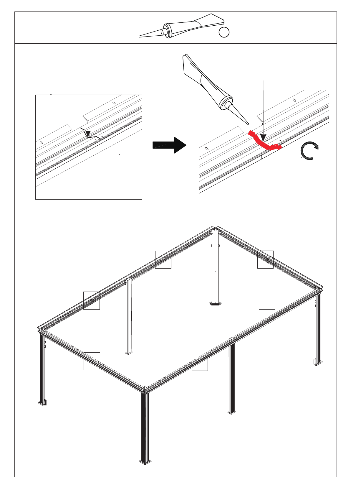
Kozyard 12'x20' Alexander hardtop gazebo with double... User manual

Assembly Manual
12‘x20’ Alexander hardtop gazebo
with double roof
Kozyard LLC Products
©
Copyright 2016 - 2019 Kozyard LLC. | All Rights Reserved.

3. Wearing protective gloves is
recommended.
4.You may need a safety hat.
6.Please use a Phillips screwdriver.
8.For ease of construction, you may
need to use a drill.
2.You will need one or more
stepladders.
5.Use the hex keys in the box.
2+
1.Two or more people are
required for assembly.
7.Do not fully tighten screws prior
to complete assembly.
15cm/5.9"
30x30cm/11.8"x11.8"
'9.01/mc333'52.11/mc343
30x20cm/11.8"x7.9"
12x20' ANCHOR BLUEPRINT
280.5cm/9.2'280.5cm/9.2'
561cm/18.4'
363cm/11.9'
591cm/19.4'

A x4 F x6
G x4
J1 x4
J2 x4
K x1
K1 x1
L x4 L1 x2
H x6 H1 x6
B x2
C x4
C1 x4
C2 x2
E x2
E1a x2
E1b x2
E2a x2
E2b x2
ITEM
A
B
C1
C2
C3
D
D1
D2
D3
E
E1a
E1b
E2a
E2b
F
G
H
H1
J1
J2
K
K1
L
L1
C
DESCRIPTION
Pole 4
2
4
4
2
2
4
4
2
2
2
2
2
2
2
6
2
4
6
4
4
4
1
1
6
Pole
Beam
Jointer Bar
Jointer Bar
Sidewall Track
Jointer Bar
Jointer Bar
Sidewall Track
Beam
Beam
Joint Bar
Jointer Bar
Union Bar
Corner Cover
Joint Cover
Joint Cover
Base
Base
Corner Solidifyng Bar
Inside Roof Connector
Outside Roof Connector
Sidewall Track
Sidewall Track
QTY
page 1
C3 x2
D x4
D1 x4
D2 x2
D3 x2

M x4 U1 x4
U2 x4
U5 x4
U3 x4
U4 x8
N1 x4
N x2
N2 x2
P x2
P1 x2
Q1 x2
Q2 x2
Q3 x2
Q4 x2
R x8
T x2
T1 x2
T2 x2
R1 x2
ITEM
M4
4
2
2
2
2
2
2
2
2
2
2
2
2
4
4
4
4
8
8
N
N1
N2
P
P1
Q1
Q2
Q3
Q4
R
T
T1
T2
U1
U2
U3
U5
U4
R1
DESCRIPTION
Corner Roof Bar
Roof Bar
Roof Bar
Roof Bar
Net Frame
Net Frame
Net Frame
Finishing End
Finishing Bar
Finishing Bar
Finishing Bar
Finishing Bar
Finishing Bar
Finishing Bar
Solidifying Bar
Solidifying Bar
Solidifying Bar
Iron Angle
Iron Angle
Finishing End
QTY
page 2

V1 x2
W1 x2
X1 x2
Y x4
Z x72
Z1 x6
Z2 x6
Z3 x2
Z4 x2
1# x301+2
2# x28+2
3# x16+2
4# x152
5# x100+2
6# x8+1
7# x48+1
8# x6+1
9# x28+2
10# x4+1
11# x12+1
Y1 x2 Ya x4 Y1a x2
X2 x2 X3 x2 X4 x2 X5 x2 X6 x2 X7 x2 X8 x2 X9 x2 X10 x2 X11 x2 X12 x2
W2 x2 W3 x2 W4 x2 W5 x2 W6 x2 W7 x2 W8 x2
V2 x2 V3 x2
V4 x2
V x8
V5 x2
V6 x2
S x160
Mosquito Sidewall
Metal Bracket
Hook Spacer
Screws
Tools
Solid Sidewall
Roof Panel
Roof Panel
Roof Panel
page 3
AA

A x4
L1 x2
1#
x20
L x4
B x2
A
A
B
L
L
L1
L1
1# 1#
1#
1#
1#
1#
1#
A1
Parts Required: Step 1:Set up Poles(Part A&Part B)with stand plates (Part L&Part L1)
using screws 1# as shown in diagram.
page 4
X4
X2

C x2 D x2 F x2
1#
x52
C1 x2
C2 x2
D1 x2
D2 x2
③
①②
D
C
D2 D1
C 2 C1
1#
1#
1#
1#
D
C
D
C
F
1# 1#
1#
1#
1#
1#
Parts Required:
Step 2:
Connect (Part C&Part D)into one beam using union bar (Part F) with screws 1#.
Connect parts(C2&D2) to the finished beam (C&D) using screws 1# as shown in diagram.
Attach Parts(C1&D1)to finished beam (C&D)using screws 1#.
Step 7: page 5
X2
C&D

Parts Required:
Long beam overall:
Step 3: Connect (Part D,E&C)into one beam using union bar (Part F) with screws 1#.
Connect parts(D1,C1,E1a&E1b) to the finished beam (D,E&C) using screws 1# as shown
in diagram.
Attach Parts(D3,E2a,E2b&C3)to finished beam (D,E&C)using screws 1#.
page 6
X4
C&E&D
D3 x2
E x2
C3 x2
E1a x2 E1b x2
E2a x2 E2b x2
C x2
C1 x2
D x2
D1 x2
F x4
1#
x96
EC
D
F F
EC
DC1
D1
C3
D3
E1a E1b
E2a E2b
①②
③
F
1#
1#
1# 1# 1#
1#
1#
1#

2#
x28
3#
x16
①
②
③
3# 3# 3# 3#
2# 2#
2#
2#
B
A
E
Parts Required:
Step 4:
Use Screws (2#&3#) to
connect poles and beams
together as shown in
diagram
page 7
X4
X4
X2
A
A
A
A
B
B
C
C
C
C
D
D
D
D
E
E
①
②
③

page 8
Parts Required:
with silicone rubber to seal
after finishing the assembly
it will be better for no water
leaking in heavy rain.
Reminder:
X4
①
①
①
①①
①
AA

J2 x4J1 x4 1#
x32
1#
1# 1#
J1 J2
Parts Required:
Step 5:
Affix the frame with corner solidifying bars
(Parts J1&J2)using screws 1# as shown in diagram.
page 8
J1
J2 J1
J2
J1
J2
J1
J2

8#
x6
9#
x28
H x4
G x4
②
①
G
H
8#
9#
9#
9#
9#
Parts Required:
Step 6:
Finish connecting beams using corner bycorner
cover (Part G) and screws 9# as shown in
diagram.
Affix middle beams using joint cover
(Part H) and screws 9# and 8# as
shown in diagram.
page 9
X4
X6
If with glass cement to seal after finishing
the assembly it will be better for no water
leaking in heavy rain.
①
①
①
①
②②
②
②
②
②

Parts Required:
Put 7 hooks to each slot of sidewall track (Part C1/Part D1)
Put 7 hooks to each slot of sidewall track Part C1 and 5 hooks to each slot sidewall track Part E1b.
Put 7 hooks to each slot of sidewall track Part D1 and 5 hooks to each slot sidewall track Part E1a.
Step 7:
page 10
After finish hooks into tracks,
then put H1 to lock them.
H1 x6
4#
x152
①
②
①
①
②
②
③
③
③
x7
x7x7
x7
x7
x7
x7x7
x5x5
x5x5
H1
H1
H1
4# H1 8#
4#
4#
4#
C1
C1
E1a
D1
E1b
D1

Parts Required:
Step 8: Set up roof frame
Connect the inside roof connect (Part K) with the conner
roof bar(Part M)and roof bar(Part N,N1,N2)using screws1#
as shown in diagram.
Attach corner roof bar (Part M) and roof bar
(Part N2,N,N1) to main frame using screw 1#
as shown in diagram.
page 11
X4
M
M
M
C
DC
A
X2
A
X4
X2
B
C
D
E
D
M
M
N1
N
N
N
N1
N1
N1
N1
N2
N2
N2
K
1#
1#
1#
1#
K
M
M
N
N1
N1
N2
N2
1#
1#
1#
1#
K x1
M x4
N1 x4
N x2
N2 x2
1#
x36
A B

P x2 Q1 x2
Q2 x2
R x4
1#
x6
P
P
Q1 Q2
Q1
Q2
Q1
Q2
1#
1# R
①①
①①
①
②
②
②
Q1
Q2
P
1#
x6
Parts Required:
Step 9:
Attach finishing bar(Part P,Q1,Q2)with
finishing end (Part R)using screws 1#
to corner roof bar(Part M)as
shown in diagram.
Affix finishing bar (Part Q1&Q2)
to roof bars(Part N,N1&N2)
using screws 1# as shown
in diagram.
page 12
X4
X2
N
M
M
N1
N2
N1

1#
x6
P1 x2
11#
x12
Q3 x2
Q4 x2
P1 P1
Q3 Q4
Q4 Q3
P1
1#11# 11#
Q3 Q4
Q3 Q4
1#
1#
11# 11#
11#
11# 1#
1#
Parts Required:
Step 10: Attach net frame (Part P1,Q3&Q4) to finishing bar(Part Q1,Q2&P) using
screws 11#&1# as shown in diagram.
page 13

K1 x1
KK1
1# 1# 1#
K1
Parts Required:
Step 11:
Connect outside roof connctor (Part K1) to inside roof (Part K) using screws 1# as
shown in diagram.
page 14

Parts Required:
Step 12:
Cover metal brackets
(Part Z,Z1,Z2,Z3,Z4) to roof
panels as shown in
the diagram.
page 15

T1 x2
T2 x2
R1 x2
T x2
R x4 1#
x12
T1
T2
V1
V2
V3 V4 VVVVV5 V6
V1
V2
V3
V4
V
V
V
V
V5
V6
T1 T2
T
1#
T
R
1#
R
R
R
R1 1# 1#
1#
R1#
T1 T2
1#
R1
TT1 T2
1# R1# 1# 1# R1 1#
V1
V2 V3 V4 VVVVV5
V6
Parts Required:
Step 13:Push the roof panels(Part V,V1,V2,V3,V4)to upper roof as shown in diagram.
Attach upper roof bar (Part T,T1,T2) to upper roof with Finish ends (PartR& R1) using screws 1# as
shown in diagram.
page 16

1#
x36
U4 x8
U3 x4
U1 x4
U2 x4 U5 x4
①
②
U4
1#
U3
1#
Parts Required:
Attach solidifying bars (Part U2&U5)or(Part U1)
together to roof bar using iron angle(Part U4) and
screws 1# as shown in diagram.
Affix solidifying bars to corner
bar using iron angle(Part U3)
and screw 1# as shown in diagram.
Step 14:
page 17
X4 X6
X2
U5 U5
U4
1# 1#
③1#
U5 U5
3.3” 3.3”5.1” 5.1”
Attention: Connect the U5 bars at the ends where the
holes are 5.1” apart to one another.
Reminder:If part U1,U2,U5 does not fix well,
loose screws 1# for adjustment.
①
①
①
①
②
②
②
②
②
②
③
③
U1
U1
U1
U1
U2
U2
U2
U2
U5
U5
U5
U5
Table of contents
Other Kozyard Shelter manuals
Popular Shelter manuals by other brands

Gazebo penguin
Gazebo penguin 7171020 instruction manual

No Butts Bin
No Butts Bin SR1606 Assembly instructions

Duratuf KIWI
Duratuf KIWI SHEDS MK2 Assembly instructions

Kiwi Camping
Kiwi Camping Oasis 3 quick start guide

IAE
IAE SHELTER Assembly & Maintenance Manual

ShelterLogic
ShelterLogic Shed-In-a-Box E Series Assembly instructions