Kramer VP-6AHD User manual

Kramer Electronics, Ltd.
USER MANUAL
Model:
VP-6AHD
1:6 UXGA / Audio / +1 CAT5 Distributor

Contents
i
Contents
1
Introduction 1
2
Getting Started 1
2.1
Quick Start 1
3
Overview 3
3.1
About the Power Connect Feature 4
3.2
Shielded Twisted Pair (STP) / Unshielded Twisted Pair (UTP) 4
3.3
Recommendations for Achieving the Best Performance 4
4
Your VP-6AHD 1:6 UXGA / Audio / +1 CAT5 Distributor 4
5
Installing the VP-6AHD in a Rack 7
6
Using Your VP-6AHD 1:6 UXGA / Audio / +1 CAT5 Distributor 8
6.1
Connecting the Balanced/Unbalanced Stereo Audio Output 10
6.2
Wiring the CAT 5 LINE IN / LINE OUT RJ-45 Connectors 10
7
Technical Specifications 11
Figures
Figure 1: Front and Rear Panels of the VP-6AHD 5
Figure 2: Underside of the VP-6AHD 6
Figure 3: Connecting the VP-6AHD 9
Figure 4: Connecting the Balanced Stereo Audio Output 10
Figure 5: Connecting the Unbalanced Stereo Audio Output 10
Figure 6: CAT 5 PINOUT 10
Tables
Table 1: Front and Rear Panel Features of the VP-6AHD 6
Table 2: Underside Features of the VP-6AHD 6
Table 3: CAT 5 PINOUT 10
Table 4: Technical Specifications of the VP-6AHD 11

Introduction
1
1 Introduction
Welcome to Kramer Electronics! Since 1981, Kramer Electronics has been
providing a world of unique, creative, and affordable solutions to the vast
range of problems that confront the video, audio, presentation, and
broadcasting professional on a daily basis. In recent years, we have
redesigned and upgraded most of our line, making the best even better! Our
1,000-plus different models now appear in 11 groups
1
that are clearly defined
by function.
Congratulations on purchasing your Kramer VP-6AHD 1:6 UXGA / Audio /
+1 CAT5 Distributor,which is ideal for:
Presentation and multimedia applications that require high quality
computer graphics and audio distribution to multiple monitors and/or
projectors
Long range graphics distribution for schools, hospitals, security, and
stores
The package includes the following items:
VP-6AHD 1:6 UXGA / Audio / +1 CAT5 Distributor
Power cord
This user manual
2
2 Getting Started
We recommend that you:
Unpack the equipment carefully and save the original box and packaging
materials for possible future shipment
Review the contents of this user manual
Use Kramer high performance high resolution cables
3
2.1 Quick Start
This quick start chart summarizes the basic setup and operation:
1 GROUP 1: Distribution Amplifiers; GROUP 2: Switchers and Matrix Switchers; GROUP 3: Control Systems; GROUP 4:
Format/Standards Converters; GROUP 5: Twisted-Pair Solutions; GROUP 6: Specialty AV Products; GROUP 7: Scan
Converters and Scalers; GROUP 8: Cables and Connectors; GROUP 9: Room Connectivity; GROUP 10: Accessories and
Rack Adapters; GROUP 11: Sierra Products
2 Download up-to-date Kramer user manuals from http://www.kramerelectronics.com
3 The complete list of Kramer cables is on our Web site at http://www.kramerelectronics.com

KRAMER: SIMPLE CREATIVE TECHNOLOGY
Getting Started
2

Overview
3
3 Overview
The Kramer VP-6AHD is a high performance distribution amplifier for
computer graphics (up to and exceeding UXGA resolutions) and HD signals
(high definition resolutions: 480p, 576p, 720p, 1080i and 1080p), as well as
audio signals. The VP-6AHD accepts:
One computer graphics input: provides correct buffering and isolation,
and distributes the signal to six outputs on 15-pin HD connectors, and one
twisted pair output
A stereo audio input signal: either
1
an unbalanced stereo audio input
signal on a 3.5mm mini jack, or a balanced stereo audio input signal on a
5-pin terminal block connector. The VP-6AHD outputs 12 stereo audio
signals simultaneously: six unbalanced stereo audio signals on 3.5mm
mini jacks, and six balanced stereo audio signals on 5-pin terminal block
connectors. If the selected audio input is unbalanced, it is converted to
balanced stereo audio; if the selected audio input is balanced, it is
converted to unbalanced stereo audio
The VP-6AHD can:
Power the receiver over the same CAT 5 cable
Be used with the TP-122 XGA / Audio Line Receiver (converting the CAT
5 signal to XGA, stereo analog and S/PDIF digital audio outputs) or with
the TP-120 XGA Line Receiver (converting the CAT 5 signal to an XGA
output)
In addition, the VP-6AHD features:
A video bandwidth of 500MHz that ensures transparent operation at all
graphics resolutions
Switches on the underside for ID Bit control and sync polarity
Front panel controls for UXGA equalization, as well as left and right
audio level controls
A transmission range of more than 300 ft. (more than 100 meters) over
UTP cabling
1 Selected via a pushbutton

KRAMER: SIMPLE CREATIVE TECHNOLOGY
Your VP-6AHD 1:6 UXGA / Audio / +1 CAT5 Distributor
4
3.1 About the Power Connect Feature
The Power Connect feature lets you power a transmitter / receiver system by
connecting just one power adapter—to either the transmitter or the receiver.
The other unit is fed via the cable connecting between the
transmitter/receiver. The Power Connect feature applies as long as the cable
can carry power. The distance does not exceed 50 meters on standard CAT 5
cable, for longer distances, heavy gauge cable should be used
1
.
For a CAT 5 cable exceeding a distance of 50 meters, separate power supplies
should be connected to the transmitter and to the receiver simultaneously.
3.2 Shielded Twisted Pair (STP) / Unshielded Twisted Pair (UTP)
We recommend that you use shielded twisted pair (STP) cable. There are
different levels of STP cable available, and we advise you to use the best
quality STP cable that you can afford. Our STP skew-free cable: Kramer
BC-SXTP, is intended for transmitting VGA signals; our non-skew-free cable:
Kramer BC-STP, is intended for digital signals.
The compliance to electromagnetic interference was tested using STP cables,
therefore we recommend using those cables.
Although unshielded twisted pair (UTP) cable might be preferred for long
range applications, the UTP cable should be installed far away from electric
cables, motors and so on, which are prone to create electrical interference.
However, since the use of UTP cable might cause inconformity to electromagnetic
standards, Kramer does not commit to meeting the standard with UTP cable.
3.3 Recommendations for Achieving the Best Performance
Achieving the best performance means:
Connecting only good quality connection cables, thus avoiding
interference, deterioration in signal quality due to poor matching, and
elevated noise levels (often associated with low quality cables)
Avoiding interference from neighboring electrical appliances that may
adversely influence signal quality, and positioning your Kramer
VP-6AHD away from moisture, excessive sunlight and dust
4 Your VP-6AHD 1:6 UXGA / Audio / +1 CAT5 Distributor
Figure 1 and Table 1 define the VP-6AHD1:6 UXGA / Audio / +1 CAT5
Distributor:
1 CAT 5 cable is still suitable for the video/audio transmission, but not for feeding the power at these distances

Your VP-6AHD 1:6 UXGA / Audio / +1 CAT5 Distributor
5
Figure 1: Front and Rear Panels of the VP-6AHD

KRAMER: SIMPLE CREATIVE TECHNOLOGY
Your VP-6AHD 1:6 UXGA / Audio / +1 CAT5 Distributor
6
Table 1: Front and Rear Panel Features of the VP-6AHD
# Feature Function
1 POWER Switch Illuminated switch for turning the unit ON or OFF
2 UXGA EQ. Trimmer Adjusts
1
the video EQ. (equalization) compensation
3 LEFT Trimmer Adjusts
1
the left output signal level
4
AUDIO
LEVEL RIGHT Trimmer Adjusts
1
the right output signal level
5 BAL. AUDIO INPUT Terminal Block
Connector
Connect to the balanced stereo audio source
6 UXGA INPUT 15-pin HD Connector Connect to the computer graphics (UXGA) source
7 UNBAL/BAL IN SELECT Button Selects balanced stereo audio when released; selects
unbalanced stereo audio when pushed in
8 UNBAL. AUDIO IN 3.5mm Mini Jack Connect to the unbalanced stereo audio source
9 Balanced AUDIO OUT Terminal
Block Connectors
Connect to the balanced stereo audio acceptors (from 1 to 6)
10 UXGA OUT 15-pin HD Connectors Connect to the computer graphics (UXGA) acceptors (from 1 to 6)
11 UNBALANCED AUDIO OUT 3.5mm
Mini Jacks
Connect to the unbalanced stereo audio acceptors (from 1 to 6)
12 LINE OUT RJ-45 Connector Connect to
2
the LINE IN RJ-45 connector on a Kramer CAT 5
receiver
3
13 Power Connector with Fuse AC connector enabling power supply to the unit
Figure 2 and Table 2 define the underside panel switches of the VP-6AHD:
Table 2: Underside Features of the VP-6AHD
# Feature Function
1 VS
4
Switch Slide the switch to the right
5
to change
the VS polarity to negative polarity
6
;
slide the switch to the left (Normal) to
retain the polarity
2 HS
4
Switch Slide the switch to the right
5
to change
the HS polarity to negative polarity
6
;
slide the switch to the left (Normal) to
retain the polarity
3 ID BIT 4
Switch
Slide to the left to set to ON
7
; to the
right to set to OFF
4 ID BIT 11
Switch
Slide to the left to set to ON
7
; to the right
to set to OFF
Figure 2: Underside of the VP-6AHD
1 Insert a screwdriver into the hole and carefully rotate it, to trim the level
2 Using a UTP cable with CAT 5 connectors at both ends (the PINOUT is defined in Table 3 and Figure 6)
3 For example, on the TP-120 XGA Line Receiver. Refer to the separate user manual: PT-110, PT-120, TP-120, WP-110,
which can be downloaded at http://www.kramerelectronics.com
4 SYNC
5 By default, both switches are set to the left
6 Downgoing syncs
7 The default. Enabling the notebook or laptop to output a VGA signal to an external VGA monitor

Installing the VP-6AHD in a Rack
7
5 Installing the VP-6AHD in a Rack
This section describes what to do before installing in a rack and how to rack
mount.
Before Installing in a Rack How to Rack Mount
Before installing in a rack, be sure that the environment is
within the recommended range:
Operating temperature range +5º to +45º C (41º to 113º F)
Operating humidity range 10 to 90% RHL, non-condensing
Storage temperature range -20º to +70º C (-4º to 158º F)
Storage humidity range 5 to 95% RHL, non-condensing
CAUTION!!
When installing on a 19" rack, avoid hazards by taking
care that:
1. It is located within the recommended environmental
conditions, as the operating ambient temperature of a
closed or multi unit rack assembly may exceed the
room ambient temperature.
2. Once rack mounted, enough air will still flow around
the machine.
3. The machine is placed straight in the correct
horizontal position.
4. You do not overload the circuit(s). When connecting
the machine to the supply circuit, overloading the
circuits might have a detrimental effect on overcurrent
protection and supply wiring. Refer to the appropriate
nameplate ratings for information. For example, for
fuse replacement, see the value printed on the
product label.
5. The machine is earthed (grounded) in a reliable way
and is connected only to an electricity socket with
grounding. Pay particular attention to situations where
electricity is supplied indirectly (when the power cord
is not plugged directly into the socket in the wall), for
example, when using an extension cable or a power
strip, and that you use only the power cord that is
supplied with the machine.
To rack-mount a machine:
1. Attach both ear brackets to the
machine. To do so, remove the
screws from each side of the
machine (3 on each side), and
replace those screws through the
ear brackets.
2. Place the ears of the machine
against the rack rails, and insert the
proper screws (not provided)
through each of the four holes in the
rack ears.
Note that:
In some models, the front panel
may feature built-in rack ears
Detachable rack ears can be
removed for desktop use
Always mount the machine in the
rack before you attach any cables
or connect the machine to the
power
If you are using a Kramer rack
adapter kit (for a machine that is not
19"), see the Rack Adapters user
manual for installation instructions
(you can download it at:
http://www.kramerelectronics.com)

KRAMER: SIMPLE CREATIVE TECHNOLOGY
Using Your VP-6AHD 1:6 UXGA / Audio / +1 CAT5 Distributor
8
6 Using Your VP-6AHD 1:6 UXGA / Audio / +1 CAT5 Distributor
The example in Figure 3 illustrates how to output a computer graphics signal
(and audio) from a computer to up to six local monitors, as well as how to
transmit it over UTP cabling to a TP-122 XGA / Audio Line Receiver.
To connect the VP-6AHD and a TP-122, do the following:
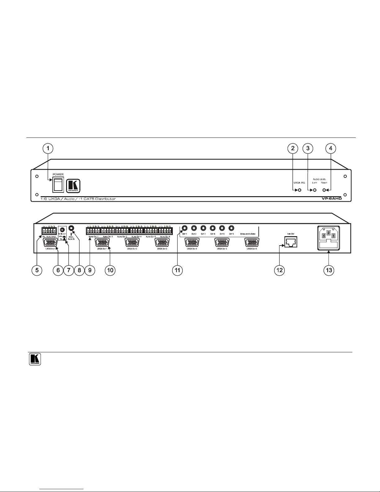
1. Connect a computer graphics source (for example, a computer) to the
UXGA INPUT 15-pin HD connector and to the UNBAL. AUDIO IN
3.5mm mini jack, for example, using a Kramer C-GMA/GMA cable
1
.
Press the IN SELECT button
2
.
2. Connect the UXGA OUTPUT 15-pin HD connectors to up to
3
six
acceptors (for example, Local Display 1 to Local Display 6).
3. Connect up to
3
12 stereo audio outputs
4
, that is, up to six:
Unbalanced stereo audio OUT 3.5mm mini jacks, and
Balanced
5
stereo audio 5-pin terminal block connectors (see section 6.1)
4. Connect
6
the CAT 5 RJ-45 LINE OUT connector
7
to the LINE IN RJ-45
connector on a Kramer CAT 5 receiver, such as the TP-122 unit.
5. Connect the power cord
8
to the VP-6AHD (not illustrated in Figure 3).
6. On the VP-6AHD:
Adjust
9
the UXGA cable compensation equalization level and/or the
audio level, if required
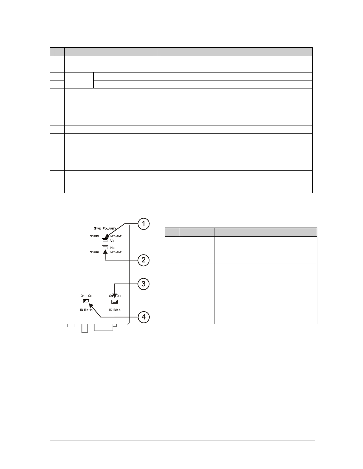
Set the ID BIT switches 4 and 11 on the underside to ON (by sliding
them to the left). This would enable a notebook or laptop (if connected
instead of a computer) to output an UXGA signal to an external VGA
monitor
1 XGA 15-pin HD(M) +Audio jack to XGA 15-pin HD(M) +Audio jack (not supplied). The complete list of Kramer cables is
on our Web site at http://www.kramerelectronics.com. Alternatively, you can connect an XGA source to the XGA INPUT 15-
pin HD connector, and a separate audio source to the UNBAL. AUDIO IN
2 Alternatively, connect a computer graphics source to the INPUT 15-pin HD connector, and a balanced stereo audio source to
the BAL. AUDIO INPUT 5-pin terminal block connector, and release the IN SELECT button
3 When not all outputs are required, connect only the outputs that are required and leave the other outputs unconnected
4 Note, that if the selected audio input is unbalanced, it is converted to balanced stereo audio; if the selected audio input is
balanced, it is converted to unbalanced stereo audio
5 By wiring the balanced outputs as unbalanced (see Figure 5) you can output 12 unbalanced stereo audio outputs
6 Via UTP cabling, with a range of more than 300ft (>100m): see section 6.1
7 The TP-122 (or TP-120) may be powered via this connector (instead of via the 12V DC external supply)
8 We recommend that you use only the power cord that is supplied with this machine
9 Use a screwdriver to carefully rotate the trimmer, adjusting the appropriate level

Using Your VP-6AHD 1:6 UXGA / Audio / +1 CAT5 Distributor
9
If necessary, slide the VS and HS switches to the right to output
negative sync polarity (or leave them in the left position (Normal) to
retain the sync polarity)
7. On the TP-122:
Connect the XGA OUT 15-pin HD connector to the XGA acceptor
(for example, a display), and connect the AUDIO OUT S/PDIF RCA
connector to the digital audio acceptor (for example, an AV Receiver),
and the ANALOG 3.5mm mini jack to the analog audio acceptor (for
example, a stereo audio recorder)
Adjust
1
the video output signal level and/or cable compensation
equalization level, if required
If necessary, set the H SYNC and V SYNC switches
2
, on the underside
Figure 3: Connecting the VP-6AHD
1 Use a screwdriver to carefully rotate the trimmer, adjusting the appropriate level
2 By default, both switches are set down (for negative V SYNC and H SYNC polarity)

KRAMER: SIMPLE CREATIVE TECHNOLOGY
Using Your VP-6AHD 1:6 UXGA / Audio / +1 CAT5 Distributor
10
6.1 Connecting the Balanced/Unbalanced Stereo Audio Output
Figure 4 and Figure 5 illustrate how to wire a balanced/unbalanced stereo
audio output connection:
Figure 4: Connecting the Balanced Stereo
Audio Output
Figure 5: Connecting the Unbalanced
Stereo Audio Output
6.2 Wiring the CAT 5 LINE IN / LINE OUT RJ-45 Connectors
Table 3 and Figure 6 define the UTP CAT 5 PINOUT, using a straight pin to
pin cable with RJ-45 connectors:
Table 3: CAT 5 PINOUT
EIA /TIA 568A EIA /TIA 568B
PIN Wire Color PIN Wire Color
1 Green / White 1 Orange / White
2 Green 2 Orange
3 Orange / White 3 Green / White
4 Blue 4 Blue
5 Blue / White 5 Blue / White
6 Orange 6 Green
7 Brown / White 7 Brown / White
8 Brown 8 Brown
Pair 1 4 and 5 Pair 1 4 and 5
Pair 2 3 and 6 Pair 2 1 and 2
Pair 3 1 and 2 Pair 3 3 and 6
Pair 4 7 and 8
Pair 4 7 and 8
Figure 6: CAT 5 PINOUT

Technical Specifications
11
7 Technical Specifications
Table 4 includes the technical specifications:
Table 4: Technical Specifications
1
of the VP-6AHD
INPUTS: VIDEO: 1 UXGA on a 15-pin
HD connector
AUDIO: 1 unbalanced stereo audio on a 3.5mm
mini jack;
1 balanced stereo audio on a 5-pin terminal block
connector
OUTPUTS: VIDEO: 6 UXGA on 15-pin
HD connectors;
CAT 5: differential encoded
XGA on an RJ-45 connector
AUDIO: 6 unbalanced stereo audio on 3.5mm
mini jacks;
6 balanced stereo audio on 5-pin terminal block
connectors
CAT 5: differential S/PDIF on an RJ-45 connector
MAX. OUTPUT LEVEL: VIDEO: XGA: 1.7Vpp;
CAT 5: 1.4Vpp, TP-120 out
AUDIO: balanced and unbalanced 26Vpp;
S/PDIF: 2Vpp, TP-122 out
BANDWIDTH (-3dB): VIDEO: XGA – 500MHz AUDIO: balanced and unbalanced >100kHz
DIFF. GAIN: 0.09%
DIFF. PHASE: 0.01 Deg.
K-FACTOR: <0.05%
S/N RATIO: VIDEO: 72dB AUDIO: 88dB
CONTROLS: UXGA: 0 to +10dB EQ.; AUDIO: 0 to +9.9dB Level
COUPLING: VIDEO: DC AUDIO: Input: AC; Output: DC
AUDIO THD + NOISE: 0.015%
AUDIO 2nd HARMONIC:
0.004%
POWER SOURCE: 230V AC, 50/60Hz (115V AC, U.S.A.) 17.5VA
DIMENSIONS: 19-inch (W), 7-inch (D), 1U (H), rack mountable
WEIGHT: 2.7kg (6lbs) approx.
ACCESSORIES: Power cord
1 Specifications are subject to change without notice

KRAMER: SIMPLE CREATIVE TECHNOLOGY
12
LIMITED WARRANTY
WHO IS PROTECTED?
WHAT IS COVERED AND WHAT IS NOT COVERED
WHAT WE WILL PAY FOR AND WHAT WE WILL NOT PAY FOR
HOW YOU CAN GET WARRANTY SERVICE
LIMITATION OF IMPLIED WARRANTIES
EXCLUSION OF DAMAGES
CAUTION!
Kramer Electronics (hereafter ) warrants this product free from defects in material and workmanship under the
following terms.
Kramer
HOW LONG IS THE WARRANTY
Labor and parts are warranted for seven years from the date of the first customer purchase.
Only the first purchase customer may enforce this warranty.
We will pay labor and material expenses for covered items. We will not pay for thefollowing:
The liability of Kramer for any effective products is limited to the repair or replacement of the product at our option. Kramer shall
not be liable for:
Thiswarranty gives you specific legal rights, and you may also have other rights, which vary from place to place.
All products returned to Kramer for service must have prior approval.This may be obtained from your dealer.
Thisequipment has been testedtodetermine compliance with the requirements of:
EN-50081: "Electromagnetic compatibility (EMC);
generic emission standard.
Residential, commercial and light industry"
EN-50082: "Electromagnetic compatibility (EMC) generic immunity standard.
Part 1: Residential, commercial and light industryenvironment".
CFR-47: FCC* Rules and Regulations:
Part 15: “Radio frequency devices
Subpart B Unintentional radiators”
Except as below, this warranty covers all defects in material or workmanship in this product. The following are not covered
by the warranty:
1. Any product which is not distributed by Kramer, or which is not purchased from an authorized Kramer dealer. If you are
uncertain as to whether a dealer is authorized, please contact Kramer at one of the agents listed in the Web site
www.kramerelectronics.com.
2. Any product, on which the serial number has been defaced, modified or removed, or on which the WARRANTY VOID
TAMPERED sticker has been torn,
3. Damage, deterioration or malfunction resulting from:
i) Accident, misuse, abuse, neglect, fire, water, lightning or other actsof nature
ii) Product modification, or failure to followinstructions supplied with the product
iii) Repair or attempted repair by anyone not authorized by Kramer
iv) Any shipment of the product (claims must be presented to the carrier)
v) Removal or installation of the product
vi) Anyother cause, whichdoes not relate to a product defect
vii) Cartons, equipment enclosures, cables or accessories used in conjunction with the product
1. Removal or installations charges.
2. Costs of
initial technical adjustments (set-up), including adjustment of user controls or programming. These costs are the
responsibility of the Kramer dealer from whom the product was purchased.
3. Shipping charges.
1. To obtain service on you product, you must take or ship it prepaid to any authorized Kramer service center.
2. Whenever warranty service is required, the original dated invoice (or a copy) must be presented as proof of warranty
coverage, and should be included in any shipment of the product. Please also include in any mailing a contact name,
company, address, and a description of the problem(s).
3. For the name of the nearest Kramer authorized service center, consult your authorized dealer.
All implied warranties, including warranties of merchantability and fitness for a particular purpose, are limited in duration to
the length of this warranty.
1. Damage to other property caused by defects in this product,damages based upon inconvenience, loss of use of the product, loss
of time, commercial loss; or:
2. Any other damages, whether incidental, consequential or otherwise. Some countries may not allow limitations on how long an
implied warranty lasts and/or do not allow the exclusion or limitation of incidental or consequential damages, so the above
limitations andexclusions maynot apply to you.
Servicing the machines can only be done by an authorized Kramer technician. Any user who makes changes or
modifications to the unit without the expressed approval of the manufacturer will void user authority to operate the
equipment.
Usethe supplied DC power supply to feed power to the machine.
Please use recommended interconnection cables to connect the machine to other components.
IF reattached, removed or otherwise interfered with.
* FCC and CE approved using STPcable(for twisted pair products)
NOTE:
Part 1:

Kramer Electronics, Ltd.
Web site: www.kramerelectronics.com
P/N: 2900-000406 REV 1
For the latest information on our products and a list of Kramer
distributors, visit our Web site: www.kramerelectronics.com,
where updates to this user manual may be found.
We welcome your questions, comments and feedback.
Caution
Safety Warning:
Disconnect the unit from the power supply before
opening/servicing.
Table of contents
Other Kramer Media Converter manuals

Kramer
Kramer VP-424C User manual

Kramer
Kramer FC-31xl User manual

Kramer
Kramer VA-256P User manual

Kramer
Kramer DigiTOOLS 7508 User manual

Kramer
Kramer FC-113 User manual

Kramer
Kramer VP-424 User manual

Kramer
Kramer FC-46 User manual

Kramer
Kramer KDS-EN6 User manual

Kramer
Kramer KDS-SW3-EN7 User manual

Kramer
Kramer VP-423 User manual

Kramer
Kramer FC-102Net User manual

Kramer
Kramer FC-321 User manual

Kramer
Kramer FC-4000 User manual

Kramer
Kramer KDS-100EN User manual

Kramer
Kramer VP-441 User manual

Kramer
Kramer VP-426C User manual

Kramer
Kramer KDS-USB2 Kit User manual

Kramer
Kramer FC-340 User manual

Kramer
Kramer OC-1N User manual

Kramer
Kramer VP-437N User manual